A bridge plug is a downhole isolation device that closes the bore at a selected depth, separating the well above it from the interval below. Conventional designs combine an anchoring system, sealing element and internal closure. The main removal options are drillable and retrievable; through-tubing describes how a tool reaches its setting location, not a separate pressure rating.
This guide explains bridge plug types, applications, selection, setting and recovery. It distinguishes established principles from product examples and includes an illustrative pressure-reversal calculation. A plug must match the actual casing or tubing dimensions, pressure direction, temperature, fluids and removal plan. The SLB bridge-plug definition provides the basic terminology; detailed operating instructions belong to the selected model.
Bridge Plug Applications
The SPE Petroleum Engineering Handbook describes bridge plugs as isolation devices used during testing, treatment, cementing and surface-equipment repair [1]. Their purpose is to stop communication through the bore, rather than to provide a normal production passage.
- Protect a lower interval: isolate perforations or a weak zone below the section planned for treatment or pressure testing.
- Restrict a treatment: keep an acid, fracturing or squeeze-cementing treatment directed toward its intended interval.
- Support planned isolation: provide a qualified bore barrier for maintenance, temporary suspension or another defined intervention.
- Provide a foundation for cement: selected tools can support a cement plug where the cementing design requires a mechanical base.
Permanent tool does not mean complete permanent abandonment. A plug inside casing does not itself close a channel behind that casing. Therefore, the well-abandonment design must identify every relevant flow path, required isolation material, placement and verification requirement. Whether one mechanical device is acceptable for a particular duty is a well-specific question.
Debris protection also needs a plan. For example, Rabia describes placing frac sand above a retrievable plug to keep cement away from its release mechanism [2]. However, this protective technique is an example, not an instruction to cover every plug. Material choice, placement and later cleanout must preserve access to the retrieving profile and equalizing passage.
Bridge Plug Categories and Types
The main bridge plug types are drillable and retrievable. Cast iron or composite describes construction. Mechanical or hydraulic describes the setting action, while wireline, workstring or through-tubing describes deployment. For example, a composite plug can be drillable, and a retrievable design may use hydraulic setting. These labels answer different selection questions.
| Description | What the label tells you | What it does not establish |
|---|---|---|
| Drillable / permanent | Destructive removal is the normal recovery strategy. | Permanent-abandonment suitability or a universal drillout method. |
| Retrievable | A release mechanism is provided for planned recovery. | Guaranteed recovery, reuse or downhole resetting. |
| Through-tubing | The running assembly passes through existing completion restrictions. | An inflatable element, openhole suitability or a universal expansion range. |
| Cast iron / composite | Identifies a material or construction family. | Pressure rating, temperature limit or suitability for a particular fluid. |
| Wireline / mechanical / hydraulic | Describes conveyance or the source of setting action. | The plug’s service rating or how it must be removed. |
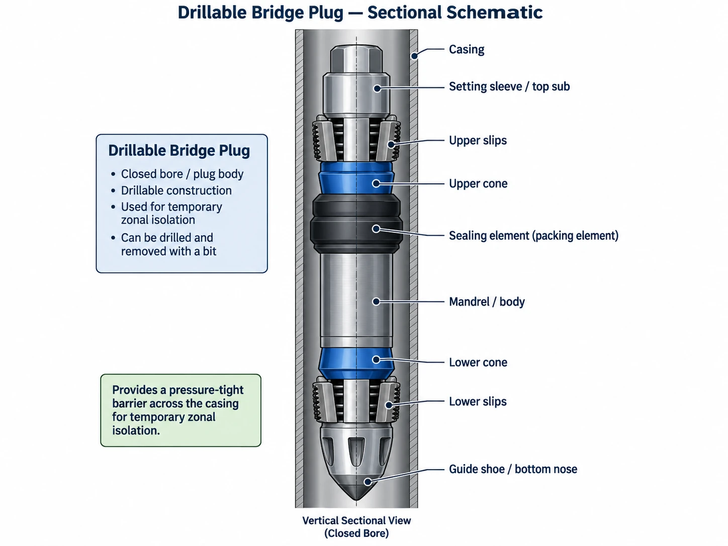
Drillable Bridge Plugs
A drillable bridge plug remains downhole unless an approved drilling or milling operation removes it. Its closed bore stops throughflow during isolation. In contrast, a cementing tool can provide a planned path for pumping slurry. Therefore, the recovery design should address plug materials, anti-rotation features, debris size, available circulation and pressure below the tool. Expected removal time is only one part of that review.
Retrievable Bridge Plugs
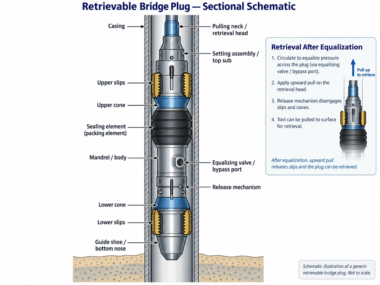
A retrievable bridge plug uses a designed release rather than routine milling. Plan the retrieving profile, access, pressure equalization and recovery equipment before installation. Deposits, cement, corrosion or deformation may prevent normal recovery, so the plan still needs a contingency. Reuse requires the manufacturer’s inspection, redress and acceptance process.
For example, the NOV NWR retrievable bridge plug has a documented recovery system. Its data sheet describes an equalizing valve and recovery with the appropriate retrieving tool. The retrieving tool is part of the recovery system, not an optional substitute for simply pulling on the plug. Therefore, check product names such as WR or NWR against the supplier’s exact drawing and part number.
Through-Tubing Bridge Plugs
A through-tubing bridge plug passes through a smaller completion bore and seals in a larger diameter below it. This can avoid retrieving the production tubing, but the entire toolstring must pass the smallest restriction. The target diameter and surface pressure-control arrangement must also be compatible with the system.
Not every high-expansion design is inflatable. For example, SLB’s Hi-Ex retrievable bridge plug uses segmented-ring technology for through-tubing isolation. Inflatable designs are another option, with their own anchoring, element and differential-pressure limits. Neither through-tubing access nor expansion capability automatically qualifies a tool for screens, perforations or open hole.
Deployment may use an appropriate wireline system, workstring or coiled tubing. Even so, a through-tubing operation may still require a rig or a well kill. Those decisions depend on well condition, access, barriers and the intervention program.
Cast-Iron, Composite and Product-Specific Designs
Cast-iron and composite designs differ in construction and drillout behavior. However, material alone does not prove suitability for high-temperature, high-pressure or erosive service. A bypass valve is a feature of a particular assembly, not an automatic property of every metal plug. Composite does not mean dissolvable. Also, do not assume that a frac plug has the same flow arrangement as a closed bridge plug.
Obtain the applicable drawing and data sheet for commercial labels. The Fas Drill and Obsidian data sheets below provide named examples. Do not infer pressure capability, retrieval method or adapter compatibility from a trade name or an abbreviated catalog label.
Bridge Plug vs. Packer vs. Cement Retainer
The quickest way to distinguish these tools is to ask which flow path remains available after setting. The following comparison describes their usual service arrangements. However, assess each specialized variant on its own [1, 2].
| Tool | Usual isolation and flow arrangement | Main engineering distinction |
|---|---|---|
| Bridge plug | Closes the bore at its setting depth while isolating the lower interval. | No intended throughflow while in its isolating state; a bypass or equalizer must be closed. |
| Production packer | Seals around the production tubing while the tubing provides a flow path. | Annular isolation is not the same as closing the tubing bore. |
| Cement retainer | Provides a controlled passage for squeeze cement through a suitable stinger or valve arrangement. | The valve and stinger govern placement and subsequent flow control. |
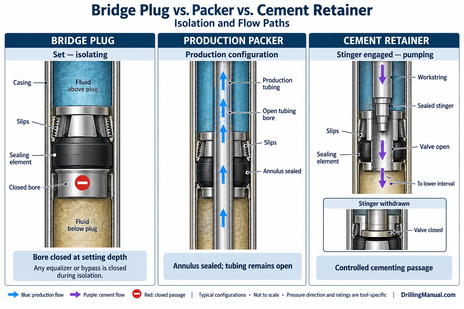
Some tool families allow conversion using approved components. However, this does not justify improvised conversion of a production packer into a bridge plug. The completed assembly must have a verified bore closure, seal, anchoring system and operating envelope.
Bridge Plug Specifications: What to Check
First, check actual bore and tool dimensions rather than nominal casing size. Check the smallest ID along the running path separately from the ID range in which the plug can seal. Include the running adapter, setting tool and any later retrieving assembly; landing nipples and other completion restrictions can govern access.
| Selection check | Information to obtain | Why the check matters |
|---|---|---|
| Access and setting bore | Minimum drift/restrictions, complete running OD, allowable setting ID and bore condition. | Passing through the well does not prove the plug can anchor and seal at the destination. |
| Pressure direction and duration | Maximum differential from above and below, cycles and required isolation period. | The two directions may have different ratings. |
| Temperature and fluids | Actual service temperature, gas/liquid duty and element/material compatibility. | A pressure rating without its test conditions is incomplete. |
| Setting equipment | Adapter, stroke, force or pressure requirements, depth correlation and release method. | A setting indication is not by itself proof of isolation. |
| Verification | Planned test direction, boundaries, acceptance criteria and pressure monitoring. | A test must address the intended barrier duty. |
| Recovery | Equalizing method, debris cleanout, retrieving profile, removal route and contingencies. | A nominally retrievable tool may become inaccessible after treatment. |
Pressure Direction and Product Qualification
Read both pressure directions. Halliburton’s Obsidian bridge plug data sheet, H06226 (November 2024), lists 10,000 psi from above and 5,000 psi from below for its listed 5½-in. versions. These catalog values apply to the named product, not to other plugs. Thus, a single headline pressure rating can be misleading.
ISO 14310:2008 covers product specifications, design verification/validation and documentation for packers and bridge plugs within a conduit. However, its scope does not cover installation and maintenance. Specify the applicable qualification and obtain the supporting records. A standards reference alone does not certify an installed plug or prescribe its field test.
Worked Example: Pressure Reversal Across a Bridge Plug
Illustrative calculation—not a test or fluid-displacement instruction. Assume a plug at 8,000 ft TVD, a static, uniform liquid column extending to surface above it, and a modeled pressure of 5,500 psig immediately below. Hold that lower pressure constant only for this simplified example. All pressures use the same gauge reference. This example ignores temperature, compressibility and friction.
For the upper column, Pabove = Psurface + 0.052 × MW × TVD, with MW in ppg and TVD in feet. Define ΔP = Pabove − Pbelow: a positive value loads the plug downward, and a negative value loads it upward. See hydrostatic pressure calculations for units and fluid-column assumptions. The SLB hydrostatic-pressure definition also documents this relationship.
| Assumed condition | Pressure immediately above plug | Differential across plug |
|---|---|---|
| 12.0 ppg; zero surface pressure | 0 + 0.052 × 12 × 8,000 = 4,992 psig | 4,992 − 5,500 = −508 psi; upward loading. |
| 12.0 ppg; 1,500 psig applied at surface | 1,500 + 4,992 = 6,492 psig | 6,492 − 5,500 = +992 psi; downward loading. |
| 10.0 ppg; zero surface pressure | 0 + 0.052 × 10 × 8,000 = 4,160 psig | 4,160 − 5,500 = −1,340 psi; upward loading. |
What the Pressure Reversal Means
The engineering point: increasing surface pressure can reverse the load direction, while reducing upper-column density can increase the upward differential. A successful test in the second state does not by itself demonstrate sealing in the other two states. Therefore, use the actual lower-zone pressure, its uncertainty and the intended operating sequence to define the load cases.
Heriot-Watt’s cementing reference distinguishes positive- and negative-differential evaluation of a squeeze job [3]. Here, the example uses that distinction as a planning question, not as a bridge-plug test procedure. Test design must also respect casing, wellhead, formation and other barrier limits. The plug’s rating alone is not the system limit.
Tools Required for Setting and Servicing
Build a model-specific equipment list covering four functions: conveyance, setting, verification and recovery. Depending on the design, it may include a wireline adapter, hydraulic or mechanical setting assembly, depth-correlation equipment, centralizers, a retrieving tool, debris-removal tools and an emergency release. Include a stinger only when the chosen tool arrangement requires one.
Match interfaces and load paths through the complete assembly. For example, a suitable drill-pipe workstring does not make an incompatible adapter acceptable. Also check restrictions in both directions. Establish how to maintain pressure control during running-tool release and later removal of isolation.
Bridge Plug Setting and Releasing Mechanisms
Wireline and Hydraulic Setting
A wireline setting assembly conveys and actuates a compatible plug. A hydraulic arrangement uses a defined pressure differential to create setting force. The tool may lock slips against the bore, energize its element and close an internal passage; the order depends on the design. Setting-tool release and the subsequent isolation test are separate events.
Tension-Set and Compression-Set Designs
Some mechanical designs use upward workstring force; others use set-down force, rotation or a combined sequence. The required movement at the plug may differ from surface movement because of friction and tubing twist. Therefore, use the specified sequence, load and contingency for that model. A quarter-turn instruction or a setting-load range from another plug is not transferable.
Retrieval: Equalize Before Releasing the Anchor
The recovery plan must address pressure before releasing the anchor. A designated equalizing passage allows communication across a retrievable plug. However, debris or cement can obstruct access or flow. The NOV NWR example above includes equalization ahead of release. Follow the approved method to verify the required pressure condition. Elapsed waiting time alone is not proof.
Also identify the pressure-control response if the plug leaks, the equalizer will not operate or normal release fails. Do not increase pulling load using generic shear-pin figures. Those figures require the actual pin arrangement, tool rating, workstring capability and manufacturer recovery procedure. Normal recovery, emergency release and drillout are separate engineered options.
Drilling and Milling a Bridge Plug
Removal planning starts with the exact plug, not a universal RPM or weight-on-bit rule. For example, Halliburton’s Fas Drill data sheet, H06160 (November 2024), lists tricone, PDC and junk-mill options. A blanket prohibition on PDC bits is therefore inappropriate. Obtain approved cutter compatibility and parameters for the tool and material being removed.
- Loss of isolation: determine when penetrating the closure can expose pressure from below and how the well-control system will handle it.
- Mechanical compatibility: assess bit or milling assembly, anti-rotation behavior, delivered WOB, torque, vibration and available power.
- Debris transport: evaluate flow rate, fluid rheology, fragment sizes, annular geometry and restrictions. A single annular velocity does not demonstrate adequate cleaning.
- Debris capture and completion protection: assess whether a junk basket or other capture arrangement is useful without creating a restriction; verify the intended bore access after removal.
Halliburton describes the Fas Drill as a top-drilling design. It permits equalization before drillout reaches the upper anchoring slips. However, that feature does not justify assuming the same sequence on every plug. Drilling into a closure changes a barrier, so the approved plan must address it.
Important Bridge Plug Features to Review
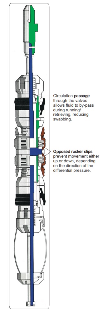
A bypass can reduce flow restriction while running or retrieving, and an equalizer can control communication before release. Keep the relevant passage closed during isolation. Opposed slips may restrain loads in both directions, but their presence does not prove equal pressure ratings or unlimited resistance to movement.
Check whether the design offers protected retrieval access, debris tolerance, suitable element support and reliable closure indication. Running clearance and any open bypass also affect surge and swab behavior. Do not interpret good clearance as permission to use an unrestricted running speed.
Bridge Plug Questions and Answers
Can cement be pumped through a bridge plug?
A conventional bridge plug blocks throughflow in its isolating state. In contrast, a cement retainer provides a controlled cementing passage. Specialized convertible or bypass-equipped tools need their correct configuration; opening a passage changes the isolation state.
Does every retrievable bridge plug need milling?
No. Its normal removal uses the designed release and retrieval arrangement. However, milling may be a contingency when that route fails. Before setting the plug, plan access, equalization and the recovery method.
Can a plug rated from above hold the same pressure from below?
Not necessarily. Obtain the ratings for both directions at the required temperature and service conditions. For example, the Obsidian data sheet above shows why you must read downward and upward differential limits separately.
Conclusion: Select for Isolation and for Removal
A suitable bridge plug must reach its setting position, seal and anchor under every intended pressure state, and support the planned removal or abandonment strategy. Select by verified geometry, pressure direction, service conditions and recovery access. The best choice is not simply the tool with the highest advertised pressure rating.
Technical References and Scope
[1] Ron Crook, “Cementing,” Chapter 9, Section 9.13.7, printed page II-423, in Robert F. Mitchell (ed.), Petroleum Engineering Handbook, Volume II: Drilling Engineering, SPE, 2006. Used for bridge-plug function and isolation applications.
[2] H. Rabia, Well Engineering & Construction, Chapter 6, Sections 12.2.1–12.2.2, printed pages 241–243. Used for lower-zone isolation during squeeze cementing, the retrievable-plug debris concern, and the stinger-operated cement-retainer distinction.
[3] Heriot-Watt University, Institute of Petroleum Engineering, Drilling Engineering, “Cementing,” Sections 5.3–5.4, printed pages 35–36, supplied 2012 course copy. Used for the difference between positive- and negative-differential evaluation; its example operations are not universal plug-test instructions.
Product and terminology sources: the linked SLB definitions, Hi-Ex description, NOV NWR data sheet (2018), Halliburton Fas Drill and Obsidian data sheets (November 2024), and ISO 14310 scope supplement the historical textbooks. Manufacturer examples apply only to the identified products and revisions; verify the documents applicable to the equipment supplied.
Engineering scope: the comparison tables and pressure-reversal example are educational analysis, not a certified barrier design or operating procedure. Final selection, installation, testing, retrieval and drillout require the approved well program and exact equipment documentation.