Formation damage is a reduction in the ability of reservoir rock near a well to transmit the fluid being produced or injected. It can result from blocked pore throats, changes in sensitive minerals, or changes in fluid saturation and relative permeability. Consequently, a damaged interval may need more pressure difference to deliver the same flow rate. [1] [3]
The practical challenge is to identify what has changed and where the restriction lies. A production decline, a high skin estimate or dirty returns can guide an investigation. However, none of these observations, taken alone, selects the correct treatment. This guide connects the main damage mechanisms with diagnosis, prevention and treatment choices. [2]
What Is Formation Damage?
Fluid approaching a producing well must pass through the rock close to the wellbore. If that region offers greater resistance, it adds pressure loss to the inflow path. At the same reservoir pressure and flowing bottomhole pressure, the well can therefore produce less than an otherwise equivalent undamaged well. The same impairment can reduce an injection well’s capacity to accept fluid. [1] [2]
Some mechanisms reduce the permeability of the pore network itself. Others reduce the effective permeability to a particular phase. For example, invading water can hinder hydrocarbon flow even when it does not permanently alter the rock framework. This distinction matters because removing solid deposits and correcting a fluid blockage involve different questions. [1] [3]
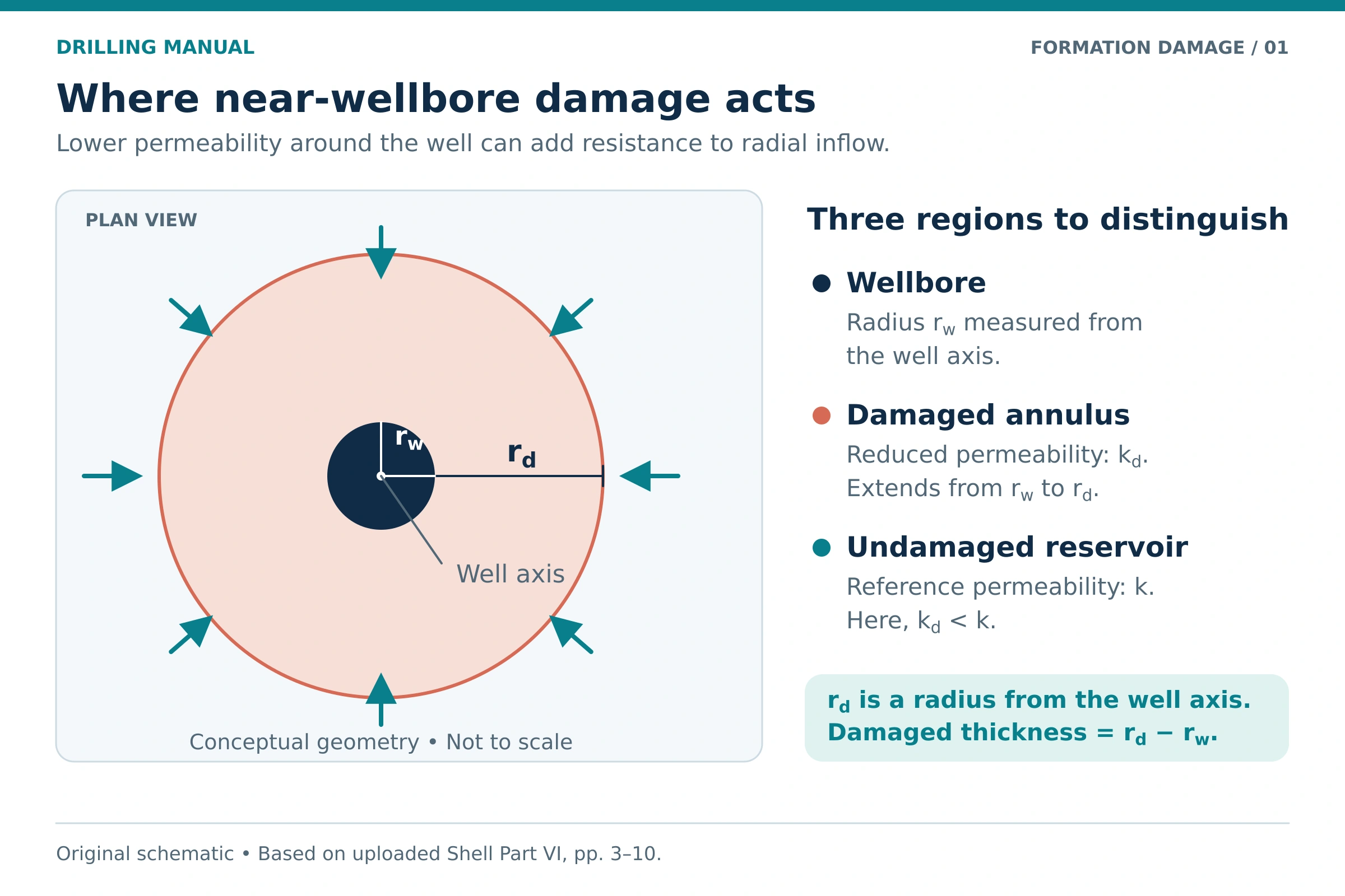
Formation damage, tubing restrictions and reservoir quality
Low production does not automatically indicate damage. Low reservoir pressure, naturally low permeability, an unsuitable tubing size or a limited artificial-lift system can also constrain output. First separate restrictions in the formation and completion from restrictions in the production system. Otherwise, a technically successful near-wellbore treatment may leave the main production limit in place. [2]
Location is equally important. Scale inside tubing and scale inside pore spaces can share a chemical description, yet they occupy different flow paths. The investigation must identify the affected location before choosing a removal or stimulation method. [2] [3]
Applications of Formation-Damage Assessment
Engineers use formation-damage assessment both before exposing a reservoir to operational fluids and after performance deteriorates. The main applications extend across the well’s life. [1] [2]
| Stage | Practical application | Main question |
|---|---|---|
| Reservoir drilling | Compare drill-in fluids, bridging materials and cleanup options. | Can the proposed system control invasion and later be removed effectively? |
| Completion and workover | Evaluate brine cleanliness, compatibility and displacement contamination. | What will contact the formation, including mixtures between fluid stages? |
| Production | Investigate changing inflow performance and possible deposits or fines movement. | Has the formation changed, or is another part of the production system limiting flow? |
| Injection | Assess suspended particles and interactions between injected and formation fluids. | Can the injected stream plug pores or create incompatible reaction products? |
| Remediation | Screen treatment candidates and evaluate their response. | Does the proposed treatment address a supported mechanism at the affected location? |
Main Causes and Types of Formation Damage
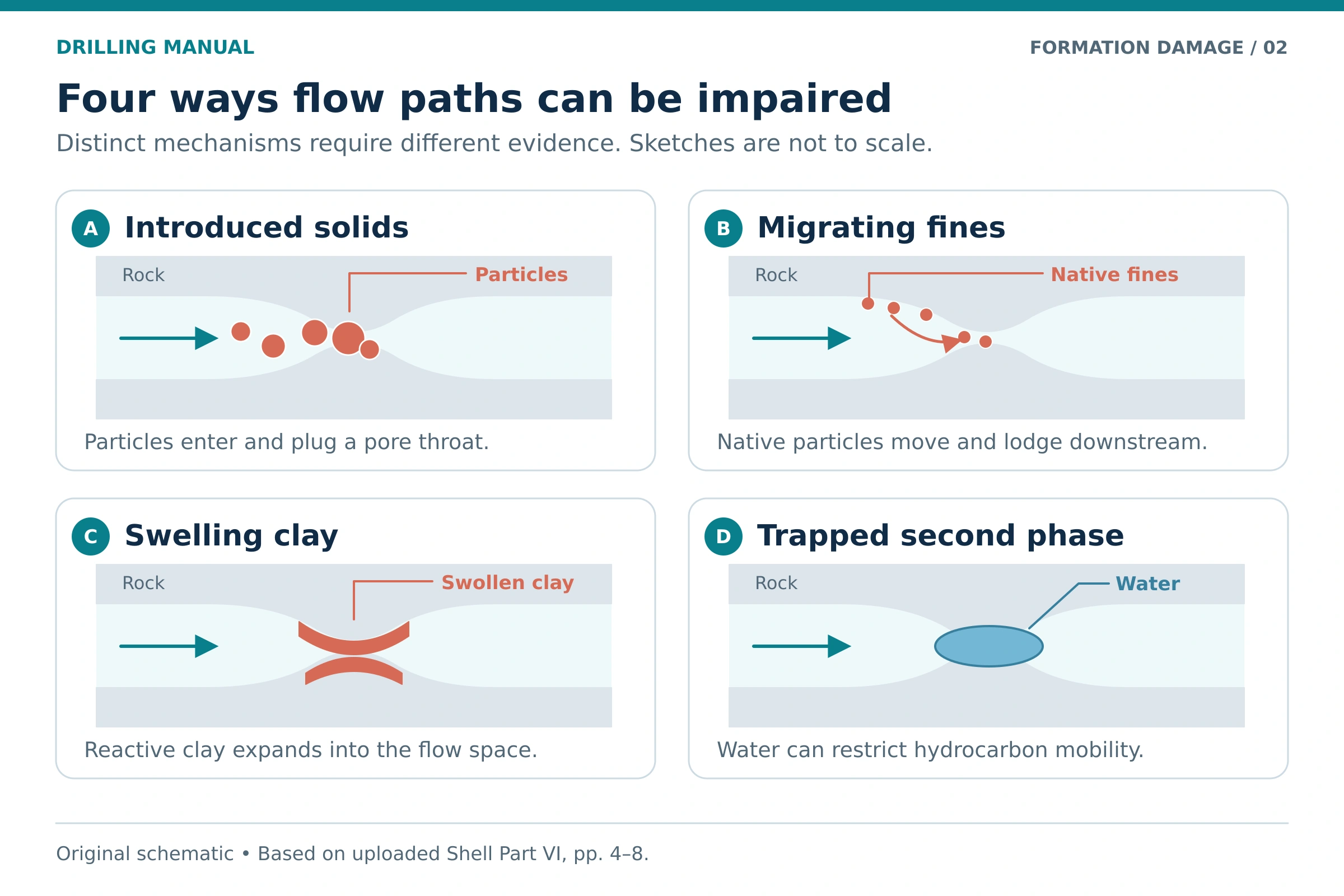
Solids invasion and pore plugging
Particles carried by drilling, completion or injection fluids can enter accessible pores and lodge at narrower passages. Their effect depends on the relationship between particle sizes and pore-throat sizes, as well as particle concentration and the conditions of invasion. A fluid name alone does not establish its damaging potential. [1]
An external filter cake forms at the borehole surface, whereas internal plugging develops within the rock. A designed external cake can help limit further invasion. However, its subsequent cleanup still matters, particularly where the completion leaves the reservoir face exposed. Losses into fractures can also carry whole fluid beyond the region controlled by ordinary surface bridging. [1]
Clay swelling and fines migration
Swelling and migration are separate mechanisms. Sensitive swelling clays can expand when the contacting fluid changes their chemical environment. In contrast, fines migration involves the release, movement and redeposition of small particles. Thus, a non-swelling particle can still obstruct a pore throat after it moves. [1] [3]
Fluid chemistry and flow both matter. Changes in ionic conditions can destabilize fines, while flow forces can transport them to restrictions. For this reason, identifying the mineral type is only part of the investigation; its location within the pore network also affects sensitivity. [1]
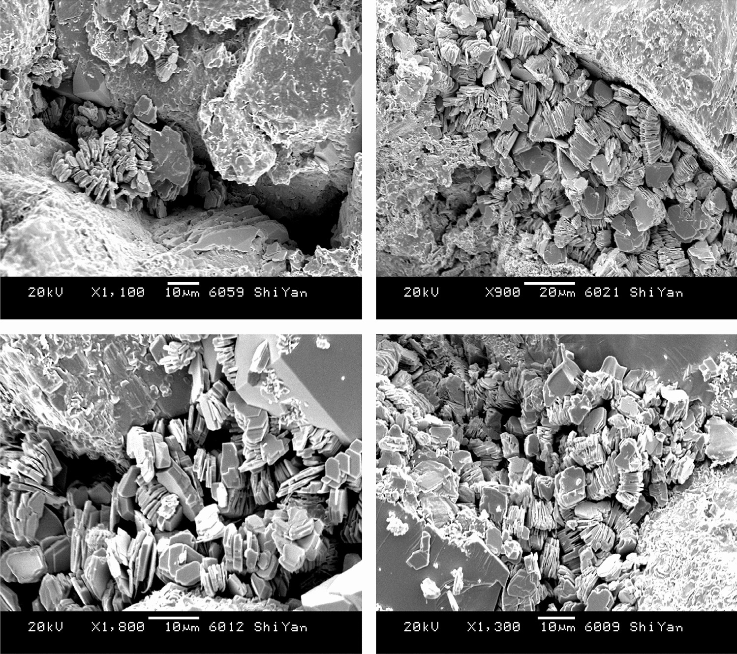
Image: Zhou, Yang & Yin (2022), Figure 6, Journal of Petroleum Exploration and Production Technology 12, 915–924. CC BY 4.0. Reproduced unchanged.
Polymer retention, precipitates and organic deposits
Polymers can impair flow through retention on mineral surfaces or plugging by poorly hydrated material. Meanwhile, incompatible aqueous fluids can form precipitates after mixing. Organic deposits, including waxes or asphaltenes, create another class of restriction. These mechanisms require different evidence, even when they produce similar performance symptoms. [1] [2]
A useful compatibility assessment therefore considers the complete contacting system: rock, formation water, hydrocarbons, operational fluids and their mixtures. Testing only a clean sample of the intended final fluid can miss an unfavorable interaction during displacement or treatment. [1] [2]
Emulsions, phase trapping and wettability changes
An emulsion can increase resistance when incompatible fluids form a difficult-to-move mixture. However, an emulsion observed at surface does not by itself prove an emulsion blockage underground. Mixing and shear through surface equipment can also produce emulsions. Samples need interpretation alongside the well history and fluid tests. [3]
Water or another trapped phase can reduce the relative permeability to the desired fluid. In gas-condensate systems, condensate accumulation provides a related example of phase-dependent flow impairment. Changes in wettability can also change fluid distribution and flow behavior. These effects should not be treated as equivalent to particles physically filling a pore. [1] [3]
Perforation damage and completion-related restrictions
Perforating can leave a damaged region around the perforation tunnel. Separately, perforation geometry, incomplete reservoir penetration and gravel-pack flow resistance can influence the pressure required for inflow. Consequently, an assessment must distinguish formation impairment from the wider completion contribution to measured skin. [2]
Factors Affecting Formation Damage
Damage severity depends on both reservoir sensitivity and the conditions of exposure. The following factors help organize a screening study; none supplies a universal acceptance limit by itself. [1] [2]
| Factor | Why it matters | What to examine |
|---|---|---|
| Pore structure and mineralogy | Narrow passages and sensitive minerals influence plugging and fluid response. | Pore-throat distribution, clay type, and the location of pore-lining or pore-filling material. |
| Particle population | Size distribution and concentration affect bridging and internal invasion. | Actual fluid solids, contamination and the selected bridging package. |
| Fluid compatibility | Mixing can trigger precipitation, clay response, emulsion formation or wettability changes. | Formation water, crude, proposed fluids and realistic mixtures. |
| Pressure and exposure | Overbalance, pressure surges, filtration and contact time influence invasion. | The anticipated exposure sequence, including static periods and fluid losses. |
| Temperature and pressure changes | Fluid stability, reaction behavior and phase conditions can change. | Representative downhole conditions, rather than room-temperature appearance alone. |
| Flow and completion geometry | Flow can mobilize fines, while geometry changes both inflow resistance and treatment access. | Rate history, interval exposure, completion type and placement constraints. |
Horizontal and long exposed intervals deserve particular attention to fluid contact and treatment placement. However, geometry also changes the productivity response to damage. A cylindrical vertical-well calculation should therefore not be transferred directly to every horizontal completion. [1] [2]
Formation Damage and Skin Factor
Why total skin is not a diagnosis
Skin is a model parameter used to express additional near-wellbore pressure behavior relative to a reference inflow model. The interpreted total can include formation damage, partial penetration, deviation, perforation effects, gravel-pack effects and other contributions. Some components can offset others. [2]
Therefore, positive total skin does not identify the material blocking the formation. Likewise, negative total skin does not establish that every part of the near-wellbore region is undamaged. Interpretation requires a suitable flow model and an understanding of the completion. [2]
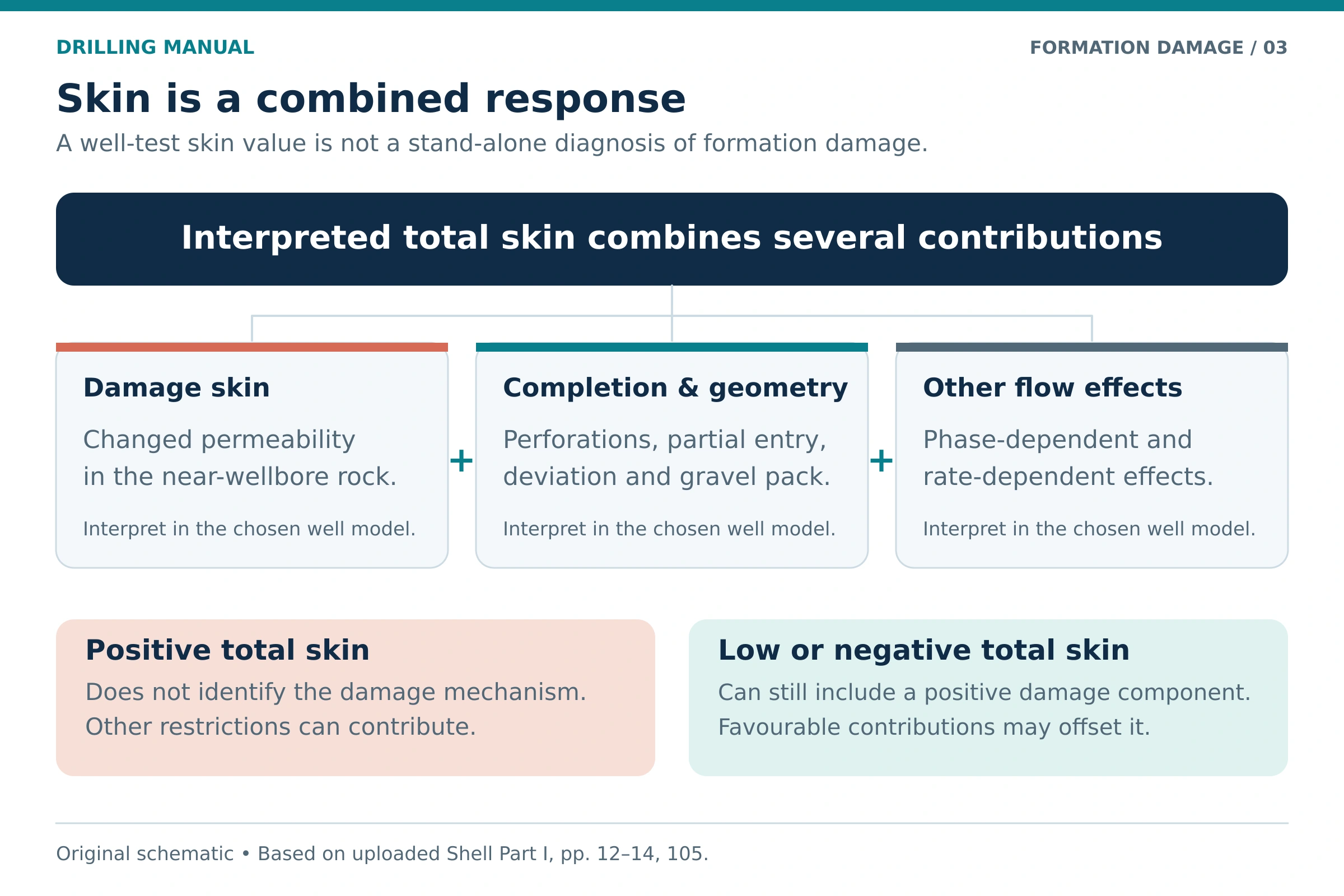
The Hawkins damage-skin equation
For a simplified cylindrical altered zone around a radial-flow well, the damage contribution can be written as follows. The equation represents a permeability contrast over an assumed radius; it does not identify the chemical or physical cause of that contrast. [1] [2]
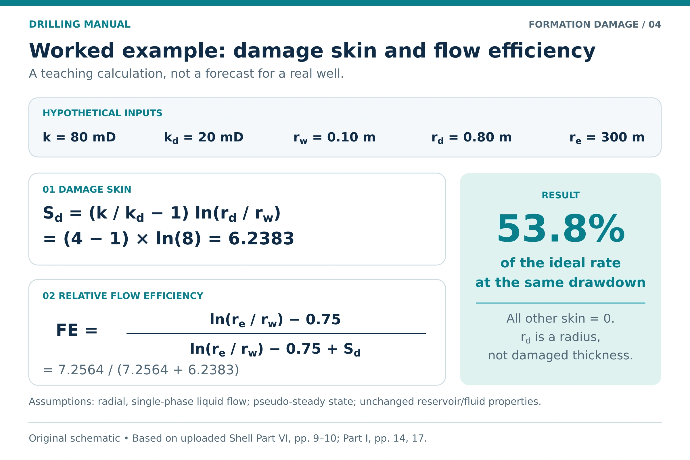
Sd = (k / kd − 1) × ln(rd / rw)
- Sd: dimensionless damage skin.
- k: permeability outside the altered zone.
- kd: permeability within the altered zone, using the same units as k.
- rd: outer radius of the altered zone, measured from the well axis.
- rw: wellbore radius, using the same units as rd.
- ln: natural logarithm.
For a damaged zone with kd < k, a smaller kd or larger rd increases the calculated damage skin. However, rd is not the thickness of the damaged ring. That thickness is rd − rw. [1]
Worked Formation-Damage Calculation
The following values are an illustrative example, not measurements from a field well. Assume a fully penetrating vertical well with radial flow of a single-phase, slightly compressible liquid in a bounded circular reservoir. The damaged zone is a uniform cylinder, and all other skin contributions are zero. [1]
| Input | Illustrative value |
|---|---|
| Undamaged permeability, k | 80 mD |
| Damaged permeability, kd | 20 mD |
| Wellbore radius, rw | 0.10 m |
| Outer damage radius, rd | 0.80 m |
| Drainage radius for the flow-efficiency comparison, re | 300 m |
Step 1: Calculate damage skin
Sd = (80 / 20 − 1) × ln(0.80 / 0.10)
Sd = 3 × ln(8) = 6.24
The damaged-ring thickness is 0.80 − 0.10 = 0.70 m. The radius ratio in the logarithm remains 8; substituting the ring thickness would change the calculation incorrectly.
Step 2: Estimate flow efficiency within the stated model
For the semi-steady radial liquid model, flow efficiency compares the actual rate with the zero-skin rate at the same pressure drawdown. The fluid properties and geometry must also be the same. [1]
FE = Qactual / Qzero-skin
= [ln(re / rw) − 0.75] / [ln(re / rw) − 0.75 + S]
Here, S means total skin. Because the example assumes every other contribution is zero, S = Sd. Using unrounded intermediate values gives:
ln(300 / 0.10) − 0.75 = 7.2564
FE = 7.2564 / (7.2564 + 6.2383)
FE = 0.5377, or 53.8%
Within this example, the damaged case delivers about 53.8% of the zero-skin reference rate. This is a model comparison, not a forecast of the gain from a proposed treatment. A real treatment may remove only part of the impairment, and other production constraints may still control the well. [1] [2]
How to Diagnose Formation Damage
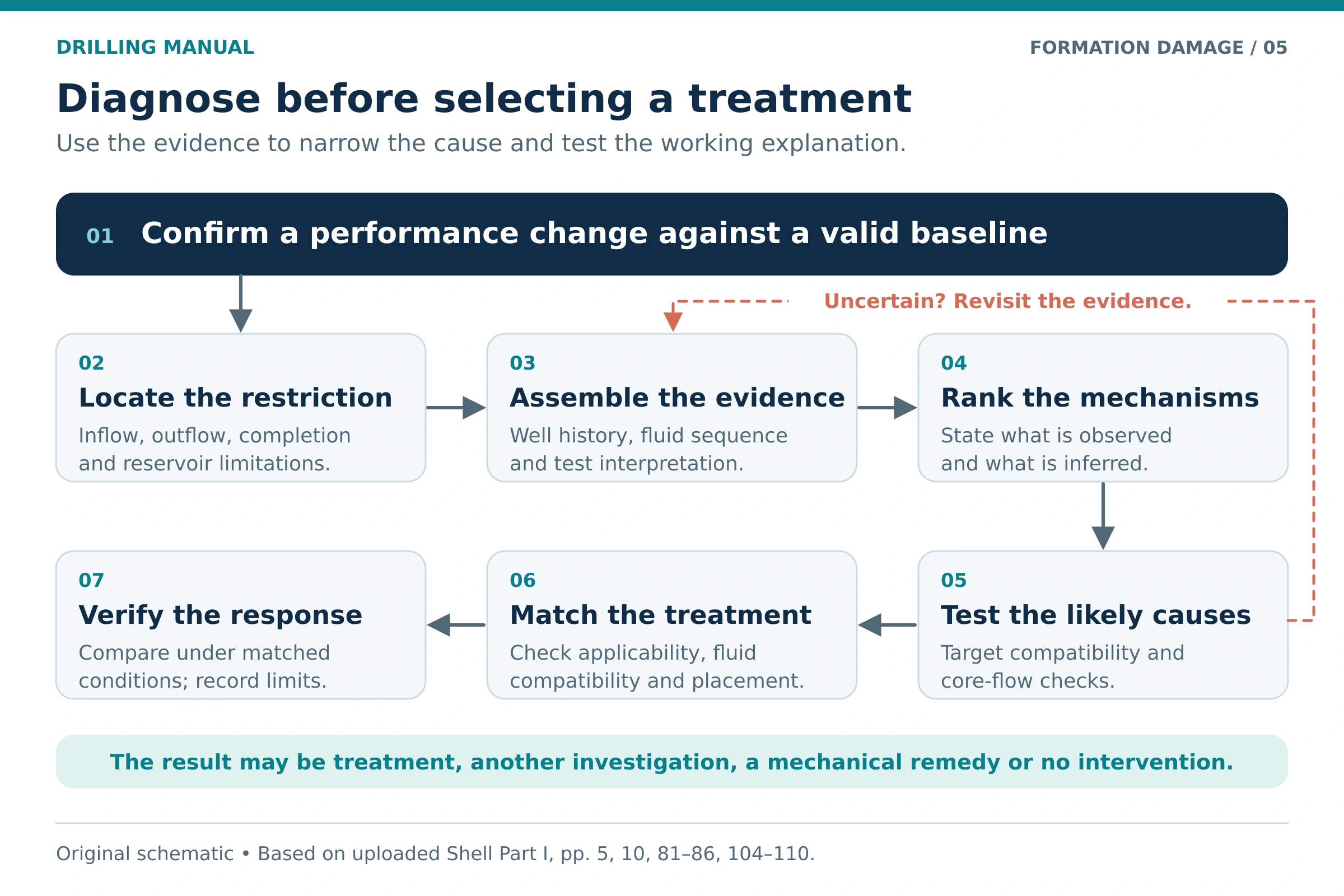
1. Establish the performance change and its timing
Begin with the pressure, rate and operational history. Look for a connection with drilling the reservoir, a fluid change, a workover, the start of injection or a change in producing conditions. Timing helps rank possible causes, but an association alone does not prove which mechanism occurred. [2] [3]
2. Separate inflow impairment from other constraints
Review the reservoir’s available pressure and flow capacity alongside the completion, tubing and lift system. Next, assess whether the available well-test interpretation supports additional near-wellbore resistance. This step avoids treating formation damage when the dominant restriction lies elsewhere. [2]
3. Connect skin and samples to plausible mechanisms
A skin estimate measures a flow effect within the chosen model; it does not distinguish clay response from scale or polymer retention. Combine it with the actual fluids used, losses, contamination history and any recovered material. Also consider whether the sampling location could have changed the sample before it reached the laboratory. [2] [3]
4. Use laboratory tests to challenge the leading explanation
Mineralogical work can identify sensitive constituents and their position within the pore system. Compatibility tests can reveal precipitation when formation water and proposed brines mix. Core-flow testing adds a direct comparison of permeability before and after an exposure sequence. These tests answer related but different questions. [1]
| Evidence | What it can help establish | Important limitation |
|---|---|---|
| Pressure/rate interpretation and skin | The presence and scale of additional inflow resistance. | Results depend on the model and completion; skin alone does not identify a deposit. |
| XRD, microscopy and thin sections | Mineral type, pore structure and potentially sensitive material. | Sample representativeness and mineral location matter. |
| Fluid compatibility testing | Whether selected fluids react or form problematic mixtures under tested conditions. | One mixture or temperature cannot represent every contact sequence. |
| Return-permeability testing | How a selected core responds to exposure and cleanup. | The result applies to the tested rock, fluids and procedure; it is not a direct well-rate prediction. |
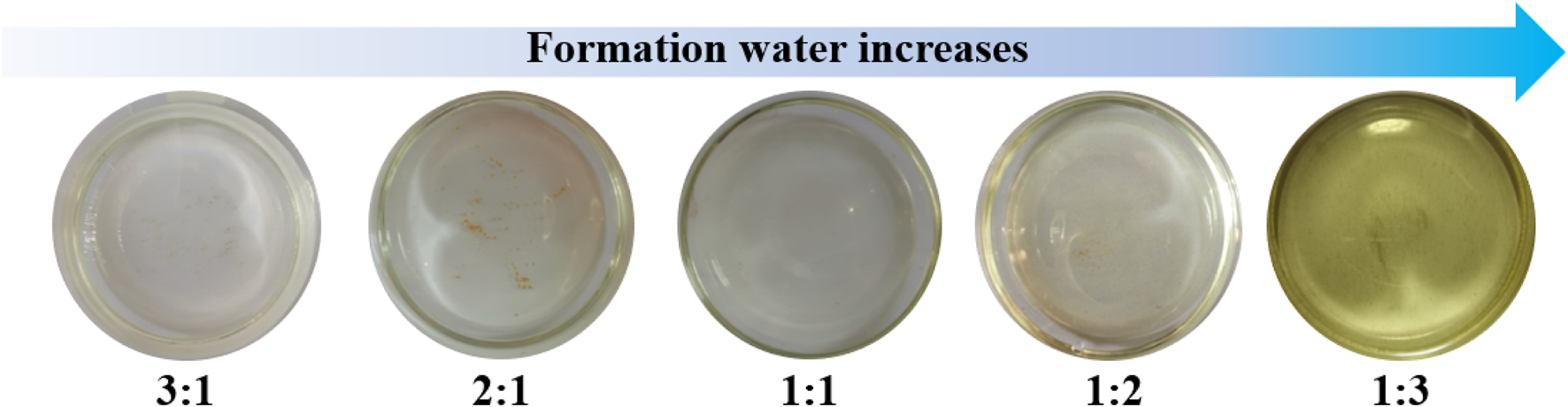
Image: © 2025 Wang, Wan, Ren, Zhu, Xu and Hu, Figure 3, Frontiers in Chemistry 13:1621714. CC BY 4.0. Reproduced unchanged.
5. Evaluate the response under comparable conditions
After a targeted intervention, compare pressure and flow behavior with the earlier baseline. A higher rate caused by greater drawdown does not, by itself, establish that the damage has been removed. Revisit the diagnosis if the evidence and the response do not agree. [1] [2]
Formation-Damage Prevention
During reservoir drilling
Select the drill-in fluid against the reservoir’s pore structure, mineral sensitivity and intended cleanup method. Particle-size distribution, filtrate compatibility and filter-cake behavior all deserve attention. In addition, manage avoidable solids contamination through appropriate solids control. [1]
Pressure management should account for invasion while satisfying the well’s control and stability requirements. Simply reducing pressure is not a complete damage-prevention design. The source material also shows why an underbalanced plan needs careful execution: a later overbalanced exposure can invade a surface that lacks a protective cake. [1] [2]
Use filtration measurements as evidence about the fluid’s behavior, rather than a complete measure of reservoir compatibility. For supporting procedures, see HPHT fluid-loss testing. The broader functions of drilling fluids still have to be satisfied alongside reservoir protection. [1]
During completion and workover
Control suspended contamination and assess compatibility with formation water and hydrocarbons. A clear-looking brine can still be chemically incompatible. Furthermore, turbidity is an optical measurement; it does not directly specify particle size or a unique solids concentration. [1]
Plan the contact between successive fluids as carefully as the final completion fluid. This includes contamination during mud displacement and fluid separation. Use completion and workover fluid testing as a procedural companion to the compatibility assessment. [1]
For an open-hole completion, connect filter-cake selection with how the exposed interval will be cleaned. A material’s laboratory solubility alone does not demonstrate that the treatment will reach and remove it throughout a long interval. [1] [2]
During production and injection
Track the conditions that could change fines movement, phase behavior or deposition. For injection, assess the incoming particle load and compatibility with resident fluids. When performance changes, preserve the operating history so the investigation can distinguish a new impairment from a change in pressure or operating conditions. [2] [3]
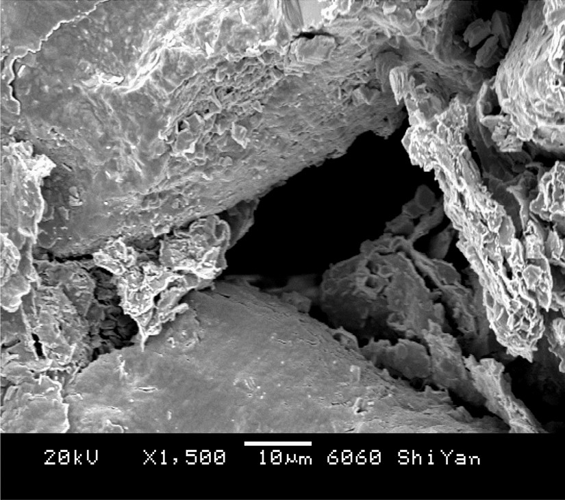
Image: Zhou, Yang & Yin (2022), Figure 8, Journal of Petroleum Exploration and Production Technology 12, 915–924. CC BY 4.0. Reproduced unchanged.
Formation-Damage Treatment Selection
Treatment selection starts with a supported mechanism and a feasible way to contact the affected interval. The following table identifies treatment families for investigation. It does not specify a pumping program, chemical concentration or operating limit. [1] [2]
| Suspected impairment | Evidence to seek | Candidate treatment family | Main limitation |
|---|---|---|---|
| Residual filter cake or polymer residue | Fluid formulation, exposure history and cleanup/core-flow tests. | A cleanup system selected for the actual cake or polymer. | Removal must reach the interval without creating a new incompatibility. |
| Acid-soluble mineral deposits or suitable near-wellbore damage | Deposit identification, mineralogy and fluid/rock compatibility. | Acid washing for accessible wellbore or perforation deposits; a designed matrix treatment for confirmed reservoir impairment. | Not every deposit is acid-soluble; reactions can generate new precipitates. |
| Organic deposits | Deposit characterization and compatibility with the proposed fluid. | A suitable solvent system. | Different organic materials need different evaluation; placement still matters. |
| Emulsion, phase blockage or adverse wettability change | Fluid behavior, contacting history and laboratory response. | A tested solvent, surfactant or emulsion-control approach, as appropriate. | The wrong fluid can worsen the interaction or fail to address the actual mechanism. |
| Fines movement or sensitive minerals | Mineralogy, fluid chemistry, flow history and representative core tests. | Laboratory-tested clay/fines stabilization where applicable; mineralogy-specific remediation for established plugging. | Stabilization does not itself remove an existing plug. Mobilizing or reacting with minerals can create further plugging. |
Why sandstone and carbonate acid treatments differ
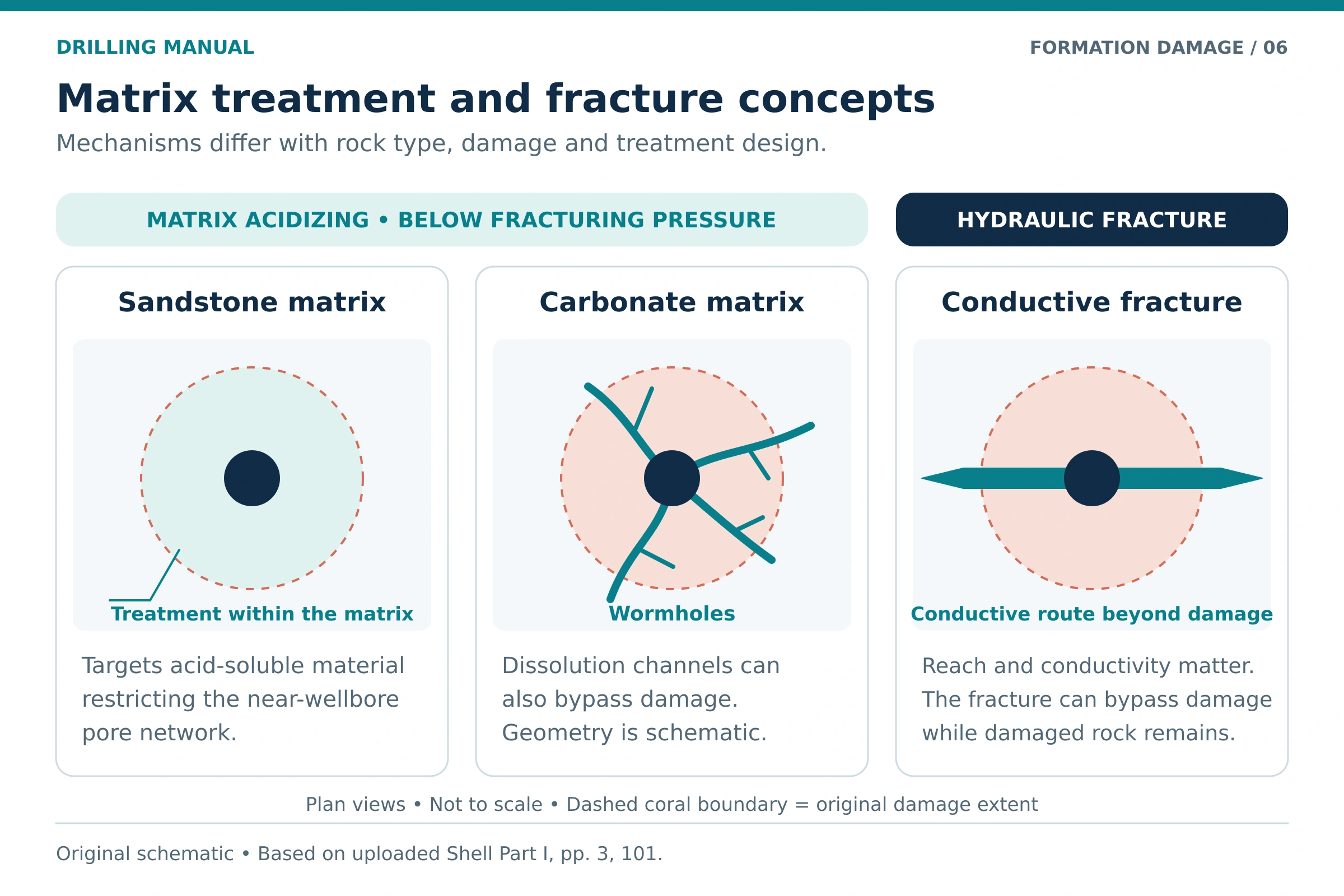
Sandstone matrix acidizing aims to remove suitable near-wellbore restrictions while accounting for mineral reactions and their products. Carbonate matrix acidizing can create preferential dissolution channels through reactive rock. These channels can bypass damage without restoring every affected pore. Accordingly, a fluid system or design assumption appropriate for one rock type should not be transferred automatically to the other. [2]
For sandstone in particular, the formation mineralogy and the nature of the damage govern the treatment choice. Acid-mineral reactions can form harmful precipitates. A general formation-damage guide therefore cannot supply one acid recipe for every well. [2]
Matrix treatment and fracture bypass
In matrix acidizing, acid enters the reservoir pore system at pressures below formation fracturing pressure. A conductive fracture can instead provide a flow path extending beyond an impaired region. These are different treatment concepts, and improved flow through a fracture does not demonstrate that the original damaged rock has regained its permeability. See the dedicated hydraulic fracturing guide for that separate treatment subject. [2]
Practical Rules of Thumb
These are qualitative screening principles drawn from the cited material. Use them to organize questions, then set acceptance criteria for the actual reservoir and operation.
- Identify the location first. A restriction in tubing, a perforation tunnel and the reservoir matrix can require different interventions. [2]
- Use skin as evidence, then investigate its components. Total skin is not a chemical diagnosis. [2]
- Judge fluids by their interactions. Clean appearance and low solids do not establish compatibility with formation water, crude or sensitive minerals. [1]
- Match particle sizes to the pore system. Avoid applying a single filtration or bridging number to every reservoir. [1]
- Plan cleanup when selecting the fluid. A useful cake during drilling must also suit the completion and the removal method. [1]
- Compare like conditions. Changes in rate, pressure and skin become more useful when their test conditions and model assumptions are clear. [1] [2]
Limitations of Formation-Damage Evaluation
Several mechanisms can operate together, so a single test may leave competing explanations. Laboratory samples also represent only the rock, fluids and exposure sequence actually tested. For example, high return permeability in one core test does not establish compatibility across every interval of a heterogeneous reservoir. [1] [3]
The Hawkins example assumes an idealized damaged cylinder. Fractures, nonuniform invasion, horizontal geometry and multiple flowing phases can require a different representation. Similarly, interpreting field skin requires accounting for the completion and the selected well-test model. [1] [2]
Finally, identifying a treatable material does not guarantee successful placement or an economic response. Reservoir deliverability, interval access and production-system limits remain relevant. The dated source manuals support the engineering principles discussed here; they are not presented as current operator procedures. [1] [2]
Formation Damage: Frequently Asked Questions
What is formation damage in oil and gas wells?
It is impaired fluid transmission through reservoir rock near the well. Solids plugging, mineral response and fluid-phase effects are among its causes. The consequence is reduced production or injection capacity under otherwise comparable conditions. [1] [3]
What is the difference between formation damage and skin?
Formation damage describes impairment mechanisms in the rock and its fluids. Skin expresses a flow effect within an inflow model. Because completion geometry and other effects can contribute to total skin, the two terms are not interchangeable. [2]
Can drilling mud cause formation damage?
Yes. Solids and filtrate can invade the reservoir, and unsuitable interactions can impair flow. However, the outcome depends on the formation, fluid design, pressure exposure and cleanup. Assess the actual system rather than assuming every drilling fluid has the same effect. [1]
Is clear completion brine always non-damaging?
No. Clarity does not prove chemical compatibility. A brine may react with formation water or affect sensitive minerals even when suspended contamination is low. Test the relevant fluids and mixtures under representative conditions. [1]
Does positive skin prove that acidizing is needed?
No. First identify the skin contributions and the likely impairment. The relevant material may not respond to acid, or the main restriction may lie outside the formation. An unsuitable acid system can also create damaging reaction products. [2]
How is return permeability calculated?
Divide the measured permeability after the selected exposure and cleanup sequence by the baseline permeability, then multiply by 100. For example, a hypothetical result of 90% describes the tested core’s permeability recovery relative to that baseline. It does not mean that the field well will recover 90% of its production. [1]
Can formation damage occur in injection wells?
Yes. Injected particles can plug pore passages, and injected fluids can interact with resident fluids or minerals. Therefore, both cleanliness and compatibility belong in an injectivity investigation. [2] [3]
Can formation damage always be reversed?
No. Removal depends on the mechanism, its location, the treatment chemistry and access to the interval. Some interventions only partly restore flow; others create a new conductive path without restoring the original pore system. Prevention and diagnosis remain essential. [1] [2]
References
The engineering discussion is based on the uploaded editions listed below. The numerical inputs are original illustrative assumptions, and the six diagrams are original schematics. The publisher link identifies the cited textbook.
- Shell. Stimulation Field Guidelines, Part VI: Drill-in and Completion Fluids. EP 2005-9059, June 2005. Formation-damage discussion: printed pp. 3–14 (PDF pp. 13–24); pressure control: printed p. 16 (PDF p. 26); cleanup: printed pp. 35–38 (PDF pp. 45–48); brine compatibility: printed p. 53 (PDF p. 63); testing and sensitivity: printed pp. 74–81 (PDF pp. 84–91).
- Shell. Stimulation Field Guidelines, Part I (Revision): Matrix Treatments. EP 2003-5188, July 2003. Introduction and matrix-treatment concepts: printed p. 3 (PDF p. 12); candidate selection and skin: printed pp. 5–18 (PDF pp. 14–27); sandstone treatment principles: printed pp. 19–26 (PDF pp. 28–35); carbonate dissolution and acid washing: printed p. 35 and pp. 39–46 (PDF p. 44 and pp. 48–55); non-acid treatments and stabilization: printed pp. 49–57 and 65–66 (PDF pp. 58–66 and 74–75); placement and testing: printed pp. 69–70 and 81–87 (PDF pp. 78–79 and 90–96); fracture bypass: printed pp. 101–102 (PDF pp. 110–111).
- Hossain, M. E., and Islam, M. R. Drilling Engineering Problems and Solutions: A Field Guide for Engineers and Students. Wiley–Scrivener, 2018. Section 3.1.6, printed pp. 104–117 (PDF pp. 122–135).