Hydraulic Fracturing, or hydro fracking, is a primary method for oil and gas wells stimulation. It is a highly engineered and complex procedure. The limitation of hydraulic fracturing application is generally to low-permeability reservoirs (e.g., < 1 Milli Darcy for gas reservoirs and < 20 Milli Darcy for oil reservoirs).
Hydraulic Fracturing Process
Successful fracture treatments may increase the productivity of a well up to 400% relative to a zero skin well. The fold of increase might be more if there was damage in the well. This may result in substantial CAPEX savings (fewer wells per field necessary) or extend the field’s economic life. Hydraulic Fracturing may be essential to break through severe formation damage (we can’t penetrate by the perforations). Or it may be desirable to increase the well productivity in low to medium-permeability reservoirs. In some cases, we would not develop a field for the success of frac treatments. However, such processes are generally expensive, so we must evaluate their economic benefit carefully.
The Fracturing Technique
Hydraulic Fracturing is pumping fluids at rates and pressures sufficient to break the formation, ideally forming a fracture with two wings of equal length on opposite sides of the well borehole. If we stopped pumping after the fracture creation, the fluids would gradually leak off (Leak Off Test) into the formation. In addition, the pressure inside the fracture would fall, and the fracture would close, generating no additional conductivity. To keep the fracture open, either utilize the to etch the faces of the fracture (an acid-frac in carbonate) to prevent them from fitting closely together or pack the fracture with proppant to hold it open.
To Create a Propped Frac
- Perforate well –efficiently.
- Pump cross-linked gel under pressure to initiate and propagate a fracture. The gel is used to minimize leak-off.
- Pump proppant to hold the frac open.
- The gel must have a ‘breaker‘ to allow the fluid to revert to a water-like consistency for ease of flow-back once the Frac is in place.
Induced Fractures
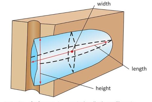
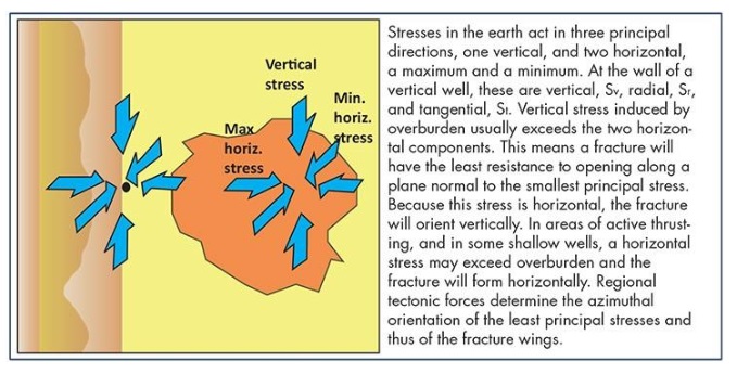
Conventional hydraulically induced fractures are almost planar, with widths typically of 2.5mm to 6.4mm (1/10th to 1/4 inch), even though lengths and heights may grow to several hundred feet. A fracture will always tend to open against the line of least resistance, so the plane of the fracture will be perpendicular to the minimum principal stress, irrespective of the deviation of the well.
In principle, a hydraulic fracturing treatment is usually a combination of stages.
- We are initiating the viscous cross-linked polymer gels at pressures exceeding the formation breakdown pressure.
- Once there is a frac, it will propagate at a slightly lower pressure.
Hydraulic Fracturing Behaviour
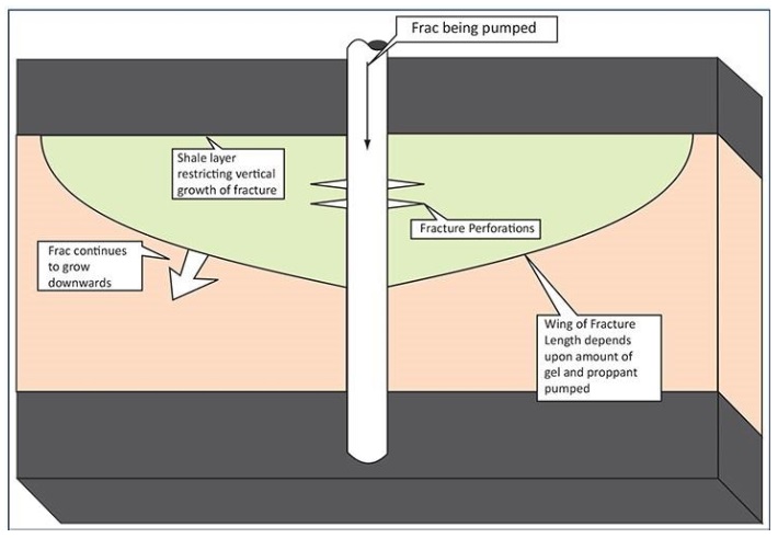
Suppose the fracture initiates in the middle of a thick, uniformly stressed body of rock. In that case, it will generally grow uniformly in all directions within the plane, resulting in a coin-shaped fracture. However, suppose a fracture initiates in a lower-stressed formation, bounded above and below by higher-stressed rocks, as is usually the case for a sandstone surrounded by shales. In that case, the shales will restrict the vertical growth of the fracture.
As a hydraulic fracture opens, the fluid begins to leak off into the formation along the Frac, driven by the difference between the fluid pressure in the fracture and the pore pressure. As the fracture area increases, the rate of leak-off from the fracture increases, so the fracture propagation rate falls. Ultimately we will reach a point of diminishing returns when the creation rate of additional fracture area by continued pumping is meager.
Minifrac
Often, we perform ‘Minifrac’ or ‘Datafrac’ – without proppant – (and the pressure decline monitored) before the main job to check the design parameters used in job planning. The on-site measurements may modify the predictions made by various computer simulations, which use historical data and rock properties taken from cores and mechanical properties logs to compute estimates of fracture lengths, pressures, etc.
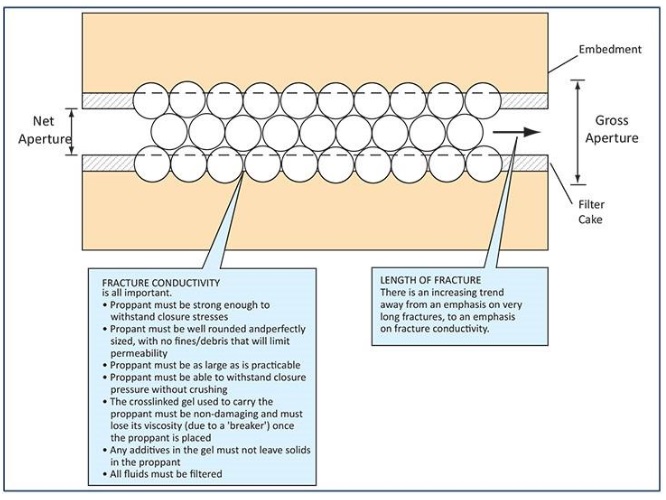
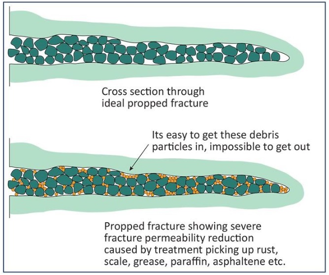
The propped Frac aims to open a channel between the reservoir and the wellbore, effectively increasing the drainage radius of the well. The Frac will deliver the hydrocarbons to the wellbore, but the rock matrix must still provide the hydrocarbons to the frac face. The pressure drop within the Frac must be low to encourage the passage of hydrocarbons; in other words, there must be good fracture conductivity.
Hydraulic Fracturing Materials
The criticality of hydrofracking additives is always high. Not only will we have to select or tune them for each application, but quality control on their properties and additions to the fluid is vital. It is not unknown for a hydraulic stimulation to fail due to incorrect additive concentrations or inability to add them due to pumping problems.
Fracture Fluids
The following characteristics of the fluid are essential or desirable:
- Good clean-up behavior to maximize fracture conductivity.
- High viscosity in the fracture – both to create width and to suspend proppant.
- Good leak-off control. We must prevent the fluid from leaking off excessively into the formation. If this were to happen, there would be no deep propagation for fracture. The fluid may deposit a filter cake, or particulate additives are sometimes used.
- Low cost – note cost alone must not be used solely or selection criteria. Value is much more critical.
- Low friction pressure to allow high-rate pumping.
- The high hydrostatic gradient minimizes surface treating pressures.
- Non-hazardous and environmentally friendly (Oil Rig Hazards). Remember, excess fluids may have to be disposed of, and pumped liquids will eventually return to the surface.
The first characteristic – good clean-up behavior is critical.
Adnoc Policy
Hydro Fracking Fluid Components
Commonly used hydraulic fracking fluids include water-based gels, oil-based gels (Oil Based Mud), oil/gel emulsions, nitrogen & CO2 foams, and lease crude. There is often a strong preference for water-based cross-linked gels.
The main constituents of water-based fluids are (we recommend that you read WBM additives & Mud Properties to understand the below items fully):
- Water – fresh or seawater unpolluted and filtered.
- Gelling agent – normally hydroxy-propyl guar (HPG), a processed form of naturally occurring guar gum. Typically added at 4.8kg per m3 (40 lbs/1,000 gals) to give a fluid with a viscosity of about 73 cp at a shear rate of 300 rpm (Fann viscometer).
- Cross-linking agent, usually a borate, titanate, or zirconate. After adding a cross-linker, the gel will form into an incredibly thick, structured, highly non-Newtonian fluid (Fluids Regimes). Under conditions in the Frac, while pumping, the apparent viscosity is probably 100 to 1,000 cp.
- Breaker to break the cross-linked gel back to a thin liquid. Either an oxidizing breaker (usually sodium or ammonium persulphate), an enzyme breaker (at low temperatures), or an encapsulated breaker. A breaker is essential to ensure fracture conductivity. Commonly Breaker concentrations are increased with pump time (cooling of the reservoir due to cold fluid injection) to optimize the polymer degradation and the fracture conductivity.
- Buffers for pH control. Most cross-linkers work under alkaline conditions: too low a pH can cause a poor cross-link, and too high a pH may result in a poor break.
- De-foamers.
- Biocide (bacteria thrive on guar gum, causing rapid viscosity loss).
- Surfactant, as an aid to clean-up.
Proppants
Proppants can be high-grade sand, intermediate-strength proppants (ISP), sintered bauxite, or ceramics. Intermediate strength proppant (MaxPROP ISP – Intermediate-strength ceramic proppant) is a mix of quartz and bauxite, ground down and stuck together to form high-strength particles with perfect sphericity. Manufactured proppants are more expensive than sand but offer higher proppant back permeabilities through higher strengths, sorting, and sphericity.
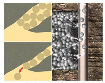
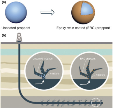
Resin-coated proppants are gaining widespread use around the world. We use them like conventional proppants. However, as the fracture closes, the temperature increases toward the original reservoir temperature. This causes the resin coating to cure, sticking together adjacent grains of proppant. This then reduces the backflow of the proppant when the well is on production. However, we must take reasonable care with resins to ensure that it does not interact with the fluid additives, especially oxidizing breakers and certain cross-linkers.
Treatment Types
Acid Fracs
The following (acid stimulation) article will mention this stimulation method.
Propped Hydro Fracking
We usually place the proppant in fractures in slurry form. First, we pump a stage of clear frac fluid, the ‘pad,’ ahead of the slurry stage to create the correct fracture dimensions. Then, we pump a slurry stage to fill that volume. As the slurry moves towards the tip of the fracture, it becomes progressively more concentrated as fluid leaks off. Usually, we pump the early part of the slurry, which we expect to reach the tip at a low concentration (probably 1 lb of proppant per gallon of frac fluid). If we pumped too high a slurry concentration early on, it could dehydrate and bridge off before reaching the end of the fracture. The slurry concentration starts gradually increasing as the treatment progresses. In a tip screen-out treatment, the pressure will increase, and pumping continues once the proppant reaches the end of the fracture – this creates width.
| Stage | Concentration (ppg/clean) | Gel Vol (1000x gal) | BBL | Slurry Vol (100x gal) | BBL | Proppant (1000x lb) | Prop Size | Pump Stage (min) | Time Cumm (min) |
| 1 | Pad | 2.2 | 53 | 2.2 | 52.8 | none | 20/40 | 2.6 | 2.6 |
| 2 | 1 | 0.9 | 220 | 1 | 23.3 | 0.9 | 20/40 | 1.2 | 3.8 |
| 3 | 2 | 0.1 | 3.2 | 0.1 | 3.4 | 0.3 | 20/40 | 0.2 | 4.0 |
| 4 | 3 | 0.2 | 5.3 | 0.2 | 6.0 | 0.7 | 20/40 | 0.3 | 4.3 |
| 5 | 4 | 0.3 | 7.3 | 0.4 | 8.6 | 1.2 | 20/40 | 0.4 | 4.7 |
| 6 | 5 | 0.4 | 9.1 | 0.5 | 11.0 | 1.9 | 20/40 | 0.6 | 5.3 |
| 7 | 6 | 0.4 | 10.6 | 0.6 | 13.3 | 2.7 | 20/40 | 0.7 | 5.9 |
| 8 | 7 | 0.5 | 11.8 | 0.6 | 15.4 | 3.5 | 20/40 | 0.8 | 6.7 |
| 9 | 8 | 4.9 | 117 | 0.6 | 158 | 39.3 | 20/40 | 7.9 | 14.6 |
Hydraulic Fracturing Planning
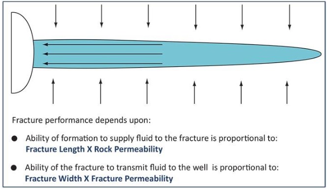
The productivity increase due to the fracturing process is a function of the following:
- Fracture length,
- Fracture conductivity,
- Fracture/wellbore communication,
- Reservoir permeability, and
- Near-wellbore damage (skin).
It is difficult to lay down firm guidelines for selecting wells, as we should consider each field or well should focus on its merits.
Input Data
When planning any hydraulic fracturing or fracking job, we should consider the risk of a frac extending ‘out-of-zone,’ i.e., below the oil-water contact or up into a gas cap. There are numerous computer programs to predict the size and shape of a frac. Like all programs, if we input insufficient data, the predictions are not worth much. Ensure that valid data is used to predict the Frac.
Data for input to the frac program includes:
- Geological data
- Formation boundaries/layers from logs
- Mechanical properties (from logs, sonic + density)
- Core data – Young’ Modulus
- Poisson’ Ratio
- Reservoir data – pressure and temperature
- Frac fluid and proppant data (for some frac models).
We should consider that if a frac prediction is wrong, it can lead to any of the following:
- Placement problems, where too much proppant is pumped for the size of the fracture;
- Or to production problems when the well flows differently than predicted.
Other Consideration For Hydraulic Fracturing
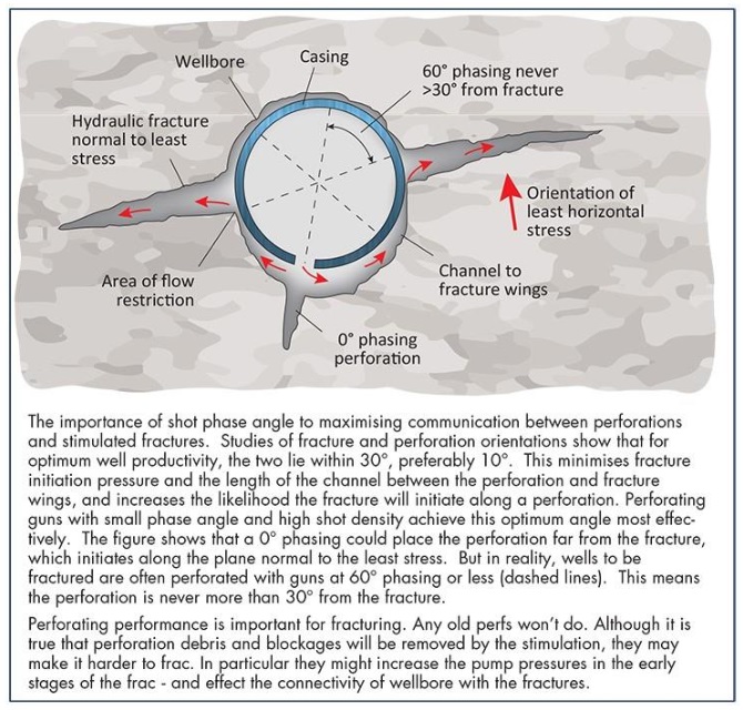
Evaluation of the competence of the cementing in drilling surrounding the perforations is essential. The perforations need to be four spf to six SPF, although higher shot densities may be beneficial. Phasing is usually 45 to 60 degrees. Oriented (180° phasing) perforating has been tried with limited success in deviated wells. Theoretically, the perforation diameter should be seven times the average proppant diameter.
Gas Wells Hydro Fracking
It is preferable to consider all low-permeability gas wells for hydraulic Fracturing, either at the completion stage or later in the life of the field. If the plan is to carry out the Frac later, it is essential to consider when designing the completion (including the casing design).
For example, in the North Sea, and well with a permeability of less than five mD or a permeability thickness (kh) of less than 700 mD.ft is a definite candidate, although we shouldn’t dismiss better wells. It is essential to consider the actual permeability distribution within the sand body.
Oil Wells Hydro Fracking
Oil wells require higher permeabilities (Absolute Permeability) to produce at commercial rates than gas wells. We can achieve the benefits of Fracturing at up to 500 mD “the best wells are the best frac candidates.” The benefits of Fracturing are potentially more significant if there is positive skin. But Fracturing is expensive, and we should always investigate other ways of removing near-wellbore damage.
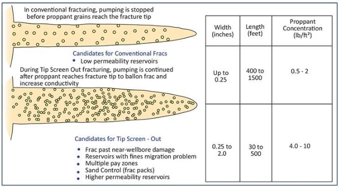
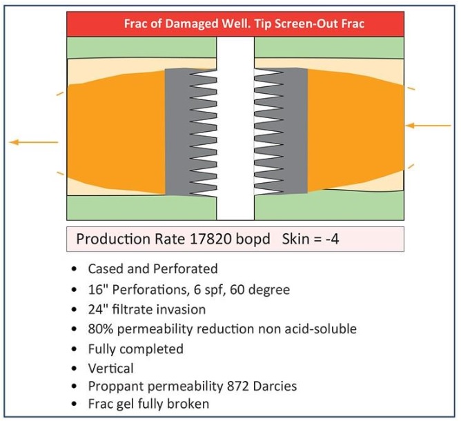
Conventional vs. Tip Screen-Out Treatments
A conventional frac is designed to be long and thin, whereas a tip screen-out (TSO) frac is intended to be fat! A TSO frac is loaded with proppant that ‘screens out, thus preventing further outward propagation of the Frac, but continued pressure increase causes the Frac to grow outwards.
Most propped hydraulic fractures will back-produce some of their proppant. Slow bean-up of wells when putting them on production is essential. It may be necessary to use special proppant knock-out pots between the well and the process facilities. Alternatively, we can resin-coat the proppant to try and bind the proppant together; alternatively, use a proprietary binding agent (e.g., plastic fibers). Experience doesn’t recommend using resin-coated proppant during the last stage only. This is because the previous proppant pumped in does not equal the first proppant to be produced.
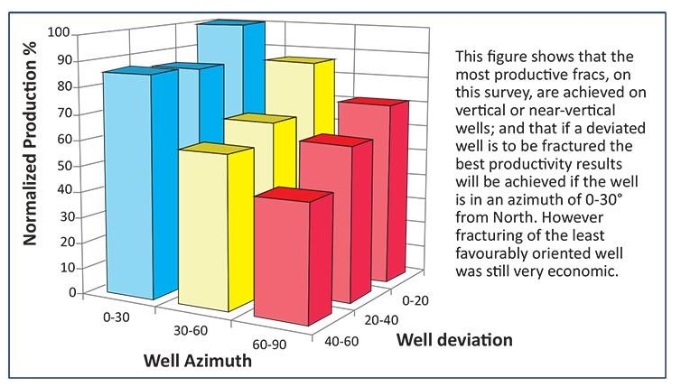
Hydro Fracking In Deviated and Horizontal Wells
Many Oil and Gas Companies recommend that hydraulic fracking is in wells with low deviation angles through reservoirs, especially wells with a high production rate due to Fracturing. This may mean drilling an S-bend well. However, we should still fracture deviated wells. In these cases, the productivity increase from Fracturing will not be as significant as from a vertical well, and the actual fracture may be more challenging to place successfully. If we know the orientation of the principle stresses – from measurements or the fault pattern – then fracture stimulation is very advantageous.
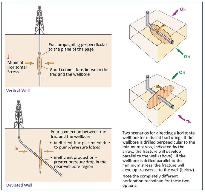
The reason for preferring fracture candidates to be low deviation is to get the maximum communication between the Frac and the wellbore, which may not happen in highly deviated wells where the Frac and the wellbore may only cross at one point. Fracture initiation and propagation pressures will be higher due to higher perforation friction losses.
Water Injectors
Many Companies believe that rock cooling and lowering the formation fracture pressure below the injection pressure (thermal fractures) are the leading causes of Fracturing in most high-rate water injection wells. Propped fracturing injectors rarely gain much – if possible, increasing the injection pressure would be better and more straightforward.
Evaluation Of Hydraulic Fracturing
Generally, there will be great care in planning a frac to get the right Frac size and shape after evaluating all the available log and core data and running numerous computer simulations. However, more often than not, very little post-frac evaluation is done.
How can we evaluate Hydro Fracking?
- Comparison of pre-frac and post-frac test data, including pressure build-up
- Multiple-isotope radioactive logging (isotopes placed in proppant)
- Temperature logging
- Bottomhole treating pressure responses
- Production logging tools (spinners)
Downhole gauges will undoubtedly aid in evaluating the bottom hole-treating pressure response. If gas lift valves have to be dummied off, then consider temporarily replacing the valves with gauges. They operate and are installed/removed precisely like a gas lift valve or dummy. Downhole memory gauges set in a nipple below a perforated joint may be an alternative; however, if left for any period downhole, they may be difficult to remove when solids settle on top of them.
Best Practices – Hydraulic Fracturing
A protection sleeve on a tubing retrievable downhole safety valve is only needed on wells where the pump pressure will cause the flow tube to retract, leaving the flapper and seals exposed. If possible, increase the control line pressure rather than use a protection sleeve. This may require a special pump and isolating the well from the shutdown system.
Prevent Damage during Frac:
- All fluids pumped must be compatible. All compatibility notes mentioned under acid apply here.
- Complete core compatibility testing (e.g., Frac Tech or Corelab) is strongly recommended.
- Reasonable quality control of frac fluids. Any cross-linked gel must break.
- Check the breaker in the heat bath on site.
- Check proppant for quality and cleanliness.
- Mix water must be unpolluted, filtered, and inhibited with NaCl or KCl (shale inhibition).
- We must thoroughly clean all pipework and tanks.
- Minimize pipe dope used on the frac string.
- ‘Flex’ the frac string before pumping the Frac.
- If using resin-coated proppant (RCP), ensure complete compatibility between resin and fracturing fluid.
- We should consider a safety valve protection sleeve (a must for wireline retrievable systems).
After The Hydraulic Fracturing Job
After a propped frac has been placed, We must take precautions to ensure proper clean out of any proppant left in the wellbore. When a frac string is pulled out, a suitable filtered fluid must be left in the hole, preferably with a degradable lost circulation material component to stop excessive losses into the Frac just formed (the same applies during the workover of a fractured well). Ideally, the well should not require killing (Wait and Weight, Driller’s method, or Volumetric Well Control Method), and a top-hole workover is only performed. Fraccing through the completion avoids any problems with workovers or well kills – however, ensure the completion can take the loads.
On Stream
When a propped-frac well is brought on stream, we should bean it up slowly to minimize the shock to the pack and thus minimize the flow-back of the proppant. Likewise, during the life of the well, we should always make rate changes gradually. We must not open the well fast while broken frac fluid flows back.
It is worth bearing in mind that we will force fluids into rocks at very high pressures yet produced back at much lower drawdowns in naturally fractured rock.
When After Completion With Some Time
When stimulating some time after the well has been drilled and completed, we must take further precautions:
Part A
- Re-perforate the zone to be fractured – old perfs can be blocked.
- Think about reducing the length of the perforation interval (e.g., to increase the stand-off from water) as needed with sand back or mechanical plugs (Bridge Plug).
- If corrosion is possible or suspected, run Kinley caliper logs and derate the burst rating of the tubing.
- We may require a tree saver – ensure it is compatible with your tree!
- Check the tubing stresses and any expansion device movement – get space out from the actual completion report.
- Also, check the liner stresses (especially if the cement bond is poor).
- Consider proppant flow back – where to put it etc.
- We should consider proppant production, velocities, erosion, cleaning of separators, etc.
- Drift the well before stimulation – check for wax, scale, etc. It must be removed if there is a lot or a small Frac. Check all tools run in the well or debris (gauge rings, dummy guns, e-line drip, trays, etc.)
Part B
- Consider the blanking of GLMs, especially if annulus pressure is required.
- Beware of cement-squeezed perforations; they may break down during the Frac. Consider patch flex or straddle.
- When using an inflatable bridge plug to isolate lower perforations, run temperature predictions to see if the plug can cope with the pressure, temperature change, and inflation ratio. Set the plug at the optimum temperature.
- Sanding back perforations is tried and tested. This can be done to ±0.6m (2 ft) in vertical wells, ± 1.5m (5 ft) in low-angle wells, and ±3m (10 ft) in higher-angle wells.
- Cleaning out of the well will probably require coiled tubing – run simulations to confirm that the proppant can be lifted with the completion and coil configuration. Consider reverse clean-outs. They can be highly effective, and despite some companies’ reluctance to use reverse circulation up the coil, they can be performed safely.
Hydraulic Fracturing References:
- Firstly, Ahmed, S., Hanamertani, A. S., Hashmet, M. R. CO. Foam as an Improved Fracturing Fluid System for Unconventional Reservoir.
- Secondly, Fracking. (2022, December 3). In Wikipedia. https://en.wikipedia.org/wiki/Fracking
- Thirdly, integrated effort is needed to mitigate fracking while protecting both humans and the environment.
- Last is the Fracturing Litigation Summary.