Geosteering is “the drilling of a horizontal or other deviated well, where decisions on well path adjustment are made based on real-time geologic and reservoir data. In conventional directional drilling, the well path is steered according to a predetermined geometric plan. The objective is to follow the line as closely as possible. Geosteering is a departure from this convention.
It is required when the geological marker is ill-defined, there are tight target tolerances, or the geology is so complicated as to make conventional deviated drilling impractical.
LWD Data In Geosteering
Logging while drilling (LWD) data can help place the horizontal wellbore in the proper position. Common LWD data are gamma-ray, resistivity, and density tools. Therefore, the directional path of the wellbore can be adjusted based on real-time logging data. Many times, these logs are included as part of the drilling program.
Applications Of Geosteering
One of the major problems when drilling horizontal wells in thin formations is establishing the well trajectory calculations as horizontal in the objective formation. It is often the case that despite the best efforts of the well site personnel, the well becomes horizontal immediately above or below the target in the reservoir. The productive hole can be lost in establishing the well in the reservoir.
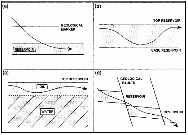
- As illustrated in Figure 1(a), geosteering enables the geological marker above the reservoir to be recognized and the final build horizontal adjusted accordingly. Typically, gamma-ray and resistivity tools identify marker formations above the producing formation.
- Figure 1(b) illustrates that only 10 to 15 feet of reservoir thicknesses are drilled. When drilling horizontally within such tight tolerances, approaching geological boundaries must be recognized early, and an appropriate directional drilling response is taken. Resistivity and gamma-ray logs are frequently affected by formations over and underlying the reservoir, thereby allowing the position of a boundary to be determined without exiting the reservoir. Drilling of the formations is invariably complicated by varying formation dip angles, varying reservoir thickness, and small faults.
- Although the reservoir may be thick, it may be desirable to remain a fixed distance above an oil-water contact or below a gas-oil contact within the reservoir to maximize production, as illustrated in Figure 1 (c). In the case of an oil-water contact, the resistivity log would be the most useful. In the case of a gas-oil contact, the density reading would provide the key.
- Several hydrocarbon blocks in highly faulted reservoirs may be connected in one wellbore, such as in Figure 1(d). The success of this operation depends on recognizing the departure from one fault block and taking appropriate steering action to enter the next fault block. Geosteering is fundamental to this and to maximizing productivity. Of course, you must know whether to drill up or down.
Sensors Distance From The Bit – (Near Bit Sensors)
A significant disadvantage that has arisen when steering (Check also: Rotary Steerable System) within tight tolerances is the distance of the various data sensors behind the drilling bit. This distance varies from 30 to 100 feet in a conventional LWD geosteering assembly. The data lag (also check: lag time in drilling article) means that changes in formation are established after the significant further hole has been drilled. Also, the directional results of the steered section are seen late. In critical applications, these disadvantages can mean maintaining the well within the objective and losing valuable productive holes. Fortunately, some tools are now available that place the data sensors within 20 feet of the bit. Some tools place the data sensors as close as three feet to the bit, with inclination at the bit being even closer.
Geosteering Alternatives
Not all horizontal wells must use LWD to be placed in the proper position. If the depth of the formation is well known, and the target interval is large enough, geosteering is not required. Other forms of geosteering are available for considerably less expense. They are drilling parameters (drilling parameters optimization) and mud logging. The combination can be used to determine the depth of the target zone.
Geologic makers can sometimes be found to determine the entry point due to penetration rate changes and formation identification. The mudlogger can look for a change in penetration rate and then look at samples to determine if the geologic marker has been penetrated, the same as using a gamma-ray or resistivity tool.
Penetration rate and sample identification are commonly used to keep the wellbore within the producing zone. The porosity of the producing zone often allows the well to be drilled with higher penetration rates than the formations above and below the zone. If the penetration rate starts to slow down and samples indicate the wellbore is exiting the zone, the TVD can be adjusted to keep it in the zone.
When using drilling and mud logging data, it is difficult to stay above an oil-water contact or below a gas-oil contact. The only way to tell if the wellbore has exited the oil section is to look at the samples. Penetration rates should remain fairly constant and do not help. Unfortunately, the wellbore must already be out of the zone before samples can be used to determine the position of the wellbore. The horizontal well intends to stay well away from the water and gas. If the wellbore is already out of oil, then the purpose of drilling the wellbore horizontally has been defeated.
Conclusion
Geosteering is generally drilling a horizontal wellbore that is ideally located within or near preferred rock layers. As interpretive analysis performed while drilling or after drilling, geosteering determines and communicates a wellbore’s stratigraphic depth location in part by estimating local geometric bedding structure.
LWD data is not necessary where drilling data and mud logging data can be used to effectively find and keep the wellbore in the zone of interest. Larger targets are easier to hit and stay in. LWD data can be used more effectively as the target size decreases, especially where the geology is not fully understood.