Before discussing drilling parameters, practices, and guidelines for drilling performance optimization, reviewing the basic concepts of Weight Indicator, Torque, and Limits is beneficial.
Basic Concepts Of Drilling Parameters Optimization For Oil & Gas Wells Operations
Weight Indicator
The weight indicator, often referred to as the `Martin Decker‘, is the most essential instrument for the driller in terms of drilling optimization and avoiding Pipe Sticking. It measures the weight hanging from the crown block, provides clues to what is happening downhole, and allows him to operate within the limits of the equipment.
The following definitions are essential:
The value shown on the driller’s weight indicator is defined as Measured Weight and includes the weight of the Traveling Equipment.
The weights observed when moving the String down and up are shown in the diagram below:
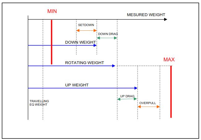
The Down Weight is the measured weight under Normal Hole Conditions when moving the string in a downward direction, without rotation, and with the mud pumps shut off. The converse is Up Weight, i.e., when moving the drill string upwards.
Every driller knows that the up weight reduces and the down weight increases when he starts rotating the string. Torque and Drag In Drilling Optimization). Rotating Weight is measured while rotating off the bottom without reciprocating.
The down Drag is the difference between the down weight and rotating weight, whilst the difference between the up weight and rotating weight is called the Up Drag.
Particular care is required when the measured weight is lower than the down weight or higher than the up weight because some form of restriction is encountered. In the former case, the difference between the measured weight and the down weight is called Setdown, while in the latter case, the difference between the up and measured weight is referred to as Overpull.
Torque
The value on the driller’s torque indicator is defined as Measured Torque. Off the Bottom, Torque is measured when rotating with the string off the bottom.
Drilling Torque is the measured torque while drilling under normal hole conditions. Increases over the drilling torque are referred to as Incremental Torque.
Limits
Maximum Pull Limits
The upper limit of the measured weight is called the Maximum Allowable Measured Weight. It is determined by the minimum of:
- The strength of the string (85% of pipe body yield strength corrected for torque).
- The pulling limit of the hoisting equipment.
Additional forces, when jarring, must be taken into account.
Minimum Pull Limits
The lower limit of measured weight is called Minimum Allowable Measured Weight, which is achieved:
- At the onset of plastic buckling deformation of the string.
- By slacking off the entire string weight if the plastic buckling limit is not reached.
Note that the limit for buckling in a stuck pipe condition, i.e. without rotation, is much lower than with rotation. In the latter case, a large allowance is made for fatigue.
Torque Limits
The upper limit of right-hand measured torque is determined by the lowest of:
- Maximum allowable torque on drill pipe corrected for pull.
- Minimum make-up torque of any connection in the string.
- The maximum torque that the rotary equipment can generate.
Monitoring of Drilling Parameters & Performance
- Closely Monitor penetration rate, rotary speed, torque, standpipe pressure, and pump stroke rate. Do this while reaming as well as when drilling a fresh hole. Ensure that the mud logging unit (or rig data system if appropriate) records all relevant parameters when drilling and reaming.
- For better optimization, continuously compare the observed drilling performance (penetration rate, torque, standpipe pressure) and drilling cuttings interpretation with the prognosis for the well. Any discrepancies between the observed and anticipated performance should be evaluated and explained.
- Use the characteristics for different drillability problems to diagnose the probable cause of any lower-than-anticipated penetration rate. Changes in torque can aid the diagnosis of many drillability problems.
- Irregular torque can indicate interbedded formations, drilling stabilizers hanging up, keyseats or doglegs, excessive weight on drilling bit, bit going under gauge, and junk in the hole.
- Increased torque may be due to higher weight on the bit, formation change (softer, higher porosity), increased inclination, thicker filter cake (potential for differential sticking), roller cone bit bearing failure, or bit going under gauge or kick.
- Reduced torque may be due to lower weight on the bit, formation change (harder, lower porosity), running on a dislodged drill pipe rubber, cutting structure wear/damage, bit balling, or bottom balling.
- Standpipe pressure should generally be steady and increase slowly with increasing hole depth. Increases in standpipe pressure may be due to annulus packing-off / stabilizers balling up, global balling of the bit body, ring-out of a PDC bit, inadequate hole cleaning, plugged nozzle or fluid passageway in a bit, PDM running at higher torque, mud viscosity increasing.
- Decreased standpipe pressure may indicate a pipe washout in the drill string, a lost nozzle, lost circulation, aeration of the mud, lower torque at PDM, and wear/damage to the downhole motor/turbine.
- However, increases in pump rate can have the exact causes of falling standpipe pressure, and decreases in pump rate can have the exact causes of increasing standpipe pressure.
General Drilling Parameters Optimization In Oil & Gas
- Operate at the weight on bit and rotary speed that give the highest penetration rate in the drill-off tests unless significant drill string vibrations are seen.
- Avoid operating drilling parameters that lead to drill string vibrations. Use a rotary speed that is high enough to give smooth rotation of the drilling string but not so high that axial and/or lateral drill string vibrations or bit whirl occur for better performance optimization.
- Do not apply excessive weight on a bit if the bit or bottom balling has been identified as potential problems or if shale is to be drilled with water-based mud.
- Keep the drilling parameter “applied weight on drilling bit” smooth once it has been optimized. Feed weight continuously to the bit using the Driller’s electric brake (Elmago, Baylor, etc) and avoid “slack-off / drill-off” – this can contribute to damaging torsional vibrations.
- The maximum allowable penetration rate, beyond which the ECD increases due to cuttings loading in the annulus exceeding the leak-off pressure, should be calculated if the penetration rate is high. Reduce the applied weight on bit and/or rotary speed to ensure that the penetration rate does not exceed the maximum allowable.
Monitor in Mud Gas
Be aware and fully appreciate that it is imperative that the gas levels in a drilling mud are correctly interpreted, and the definitions are strictly adhered to. This is particularly critical during pipe-tripping operations.
Pore pressure, or specific potential kick causes, can only be assessed accurately based on observations of trip gas, connection gas, swab gas, and pump-off gas. If any of these are observed, pore pressure levels are close to mud hydrostatic.
Increasing background gas levels can indicate increasing pore pressure if correctly determined and analyzed – the drilled gas level content of background gas must be understood.
For definition purposes, the level of gas in the mud is due to one or a combination of the following:-
- Background Gas: The general level of gas carried by the mud purely as a function of circulating in an open hole.
- Drilled Gas: Gas that has entered the mud due to the actual drilling of the formation, i.e. the gas contained in the matrix of the rocks which have been drilled.
- Connection Gas: The gas which enters the mud when a connection is made due to a reduction in hydrostatic due to loss of ECD and due to swabbing while pulling back.
- Swabbed Gas: The gas which enters the well due to swabbing. This may be caused by tripping or by simulating tripping.
- Trip Gas: The gas which enters the mud during a trip is measured after a trip has taken place.
- Pump Off Gas: The gas which enters the mud due to turning off the mud pumps and removing ECD from the hydrostatic pressure on the bottom of the well.
Monitoring of Drilling Cuttings For Better Performance Optimization
- Cuttings samples should be collected regularly at the shakers.
- The collected cuttings should be examined and interpreted promptly after collection.
- They will confirm an expected or unexpected formation change, aid the interpretation of penetration rate and torque changes, and help discriminate between different causes of reduced penetration rate, e.g., bit wear versus harder rock.
- Large cavings can indicate mechanically induced wellbore instability problems and may indicate an increase in pore pressure gradient. The shape of cavings can help identify the mechanism that caused them to enter the well. The caving mechanism influences the appropriate corrective action.
- The presence of rubber in the cuttings often indicates problems with the downhole motor. The metal in the cuttings can indicate problems with the bit or downhole motor or damage to the wellhead, casing, or downhole equipment.
- The lag time is when cuttings are transported from the bit to the surface. The lag depth is the depth from which the cuttings originate, not the bit depth when they reach the shale shakers. The lag time and depth should be calculated and updated as often as feasible to avoid misinterpretation of the formation depth from which the cutting samples originated.
- The effects of high penetration rates and borehole instability on the depth resolution of cuttings should be considered when concluding cuttings.
- The impact of the over-gauge holes on lag time and depth should be considered if there is any potential for hole enlargement.
- Closely monitor shakers and drilling cuttings volume trend to assess hole cleaning for better performance optimization.
Reference: ABC of Stuck Pipe, Shell U.K. Exploration and Production.