This article aims to show the directional well trajectory calculation methods required for all well profile design planning, including build, hold, and drop sections, and to show the utilization of trajectory and directional survey calculation methods by designing the well path of two wells. Please note that this article is one of our Directional Drilling Guide Articles.
The focus will be on is on the following items:
- Calculate directional coordinates.
- Calculate (TD) the total Depth, (KBTVD) the true vertical depth, and vertical departure at (EOB) interval in a build and hold well profile.
- Calculate directional coordinates.
- Give formulas for calculating the directional well trajectory for several methods: Tangential, balanced tangential, average angle, the radius of curvature, and minimum curvature.
Types of Directional Well Profiles For Trajectory Calculation
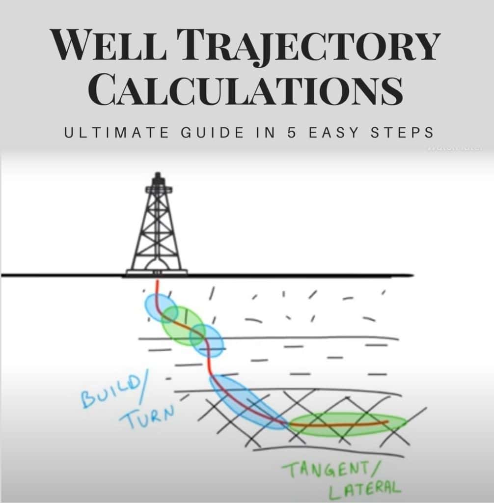
Before starting the well trajectory calculations steps for well profile design, we shall explain the different directional types of well profiles, which are mainly four types.
Build and Hold Directional Well Planning Profile Design
This type of directional well trajectory profile consists of:
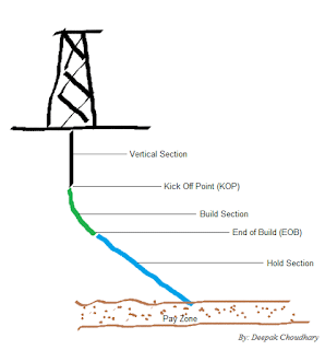
- Vertical section.
- Kick-off point.
- Build-up section.
- Hold section up to target.
This directional well trajectory profile calculation is consistently used when drilling single-completion shallow wells.
- First, the wells can be vertically drilled to the kick-off point (shallow Depth).
- Then, the well is deflected smoothly until a maximum inclination angle with the desired azimuth.
- After that, it is preferred to run casing if this is applicable.
- Finally, keep holding inclination and azimuth (HOLD) until the well target.
Directional Well Planning – S profile Design (Build, Hold, and Drop)
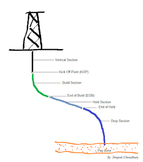
This type of Directional well trajectory profile Design has a disadvantage: it will produce higher torque and drag for the exact horizontal departure. S profile well design consists of the following:
- Vertical section.
- Kick-off point.
- Build up section.
- Hold section.
- Drop off section.
- Hold section up to target.
Application:
- For sidetrack Drilling.
- To avoid faults.
- To hit multiple targets.
- To decrease the inclination in a specific interval.
Continuous Build Directional Well Planning – J Profile Design
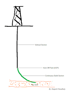
They are the same as the Build and Hold Directional Well Trajectory Profile Calculation, except that the kick-off point is deeper. This type of directional well profile consists of:
- Vertical section.
- Kick-off point (deep).
- Build-up section.
Horizontal Directional Well Planning Profile Design
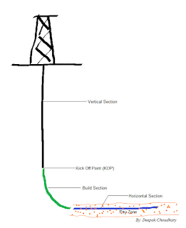
This directional well trajectory profile consists of one of the above profiles and a horizontal section within the required target interval. The horizontal section is usually drilled at 90 degrees. Hence, the extra equations involved are to get the length of the horizontal section to calculate the total well departure and total measured depth. The hole total KBTVD usually remains the same as the KBTVD of the well at the start of the horizontal section, as there are no dip variations within the reservoir. Its applications are as follows:
- To connect the productive portions of the reservoir.
- To increase productivity from low permeability reservoirs by increasing the amount of formation exposed to the wellbore.
- To produce thin oil zones with water or gas coning problems.
- To maximize production from reservoirs that are not efficiently drained by vertical wells.
Planning The Well Profile
We must design the 3d wellbore trajectory to hit a given target to start planning a directional well. The first thing to consider is selecting the most economical design for the directional drilling trajectory profile. Of course, we shall think which build, hold, or drop trajectory calculation suits us.
The Target
The geologist specifies the target and will not merely define a certain point as the target but also specify the acceptable tolerance (e.g., a circle of radius 100 feet having the exact target as its center). A target zone should be selected as large as possible to achieve the objective. If multiple zones are to be penetrated, various targets should be chosen so that the planned pattern is reasonable and can be achieved without causing excessive drilling problems. After selecting the target, head to select the most applicable well pattern.
Allocation Of Slots To Target
Even this is more complex than we would think. From a directional driller’s viewpoint, slots on the northeast of the platform (platform rigs) or pad should be used for wells whose targets are in a North Easterly direction. However, other considerations generally exist (e.g., water injection wells may have to be grouped for manifolding requirements). Also, as more wells are drilled and the reservoir model is upgraded, it has been known that targets will be changed!
The inner slots are used to drill to the innermost targets (i.e., those targets at the smallest horizontal distances from the platform), and these wells will be given slightly deeper kick-off points. The outer slots drill to the targets furthest from the platform. These wells will be given shallow kick-off points and higher build-up rates to keep the maximum inclination of the well as low as possible.
Kick-Off Point & Build-Up Rate In Well Trajectory Calculation
The kick-off point and build-up rate selection depend on many factors, including the hole pattern selected, the casing design program, the drilling fluid program, the required horizontal displacement, and the maximum tolerable inclination. The choice of kick-off point may be severely limited by the requirement to keep the well path safe from existing wells. The shallower the KOP and the higher the build-up rate, the lower the maximum inclination to reach a given target.
In practice, we may perform the well trajectory calculations for several KOP and build-up rate choices, then compare results. The optimum option is to give a safe clearance from all existing wells, keep the maximum inclination within desired limits, and avoid unnecessarily high dogleg severities.
Tangent Section In Well Trajectory Calculation
During the eighties, several extended-reach drilling projects were completed. If wells are drilled at inclinations up to 80°, the area that can be covered from a single platform is approximately eight times that covered if the maximum inclination of the wells is limited to 60°. However, inclination angles over 65° may result in excessive torque and drag on the drill string (drill string design) and present hole cleaning, logging, casing, cementing, and production problems. These problems can all be overcome with today’s technology but should be avoided whenever there is an economical alternative.
Experience over the years, directional control problems are aggravated when the tangent inclination is less than 15°. This is because there is more tendency for bit walk to occur (i.e., change in azimuth), so more time is spent keeping well on course. To summarise, most run-of-the-mill directional wells are still planned with inclinations in the 15° – 60° whenever possible.
Drop Off Section
On S-type wells, the drop-off rate is selected mainly regarding ease of running casing and avoidance of completion and production problems. It is much less critical concerning drilling because there is less tension in the drill pipe that is run through this deeper dogleg, and less time will be spent rotating below the dogleg.
The Horizontal Projection In Well Trajectory Calculation
On many well plans, the horizontal projection is a straight line drawn from the slot to the target. To avoid other wells, starting the well in a different direction is sometimes necessary on multi-well platforms. Once clear, the well is turned to aim at the target. Of course, this is a 3-dimensional turn, but it typically looks like the Figure below on the horizontal plane.
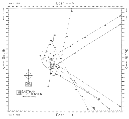
The path of the drilled well is plotted on the horizontal projection by plotting total North/South coordinates (Northings) versus whole East/West coordinates (Eastings). These coordinates are calculated from surveys.
Lead Angle
In the old days (pre-1985), it was standard practice to allow a “lead angle” when kicking off a well. Since roller cone bits used with rotary assemblies tend to “walk to the right,” the wells were generally kicked off in a direction several degrees to the left of the target direction. In extreme cases, the lead angles could be as large as 20°.
The significantly increased use of steerable motors and the widespread use of PDC bits for rotary drilling have drastically reduced the need for wells to be given a “lead angle.” Many wells today are deliberately kicked off with no lead angle (i.e., in the target direction).
Well Trajectory Calculations
First, Parameters To Define The Directional Well Profile | Trajectory Design
Three essential parameters shall be defined before starting any well trajectory calculation, which is as follows:
- Kick Off Point
- Build-Up & Drop-Off Rate
- Tangent / Drift Angle
Kickoff Point
Which is the MD at which the well is planned to be deflected vertically, a change in inclination is started, and the well is oriented with specific azimuth (north, south, east, and west).
Simple Hints:
- The shallowest KOPs will result in a decrease in the tangent section inclination. Also, it will be more difficult to kick off well on deeper formations.
- The well-starting kick-off should happen in more stable formations.
Build-up and drop-off rate
In well planning and trajectory calculation profile design, we use the term build-up and drop-off rate, which are the rates of the well deflected from zero degrees (vertical) (usually measured in degrees per 30 m or 100 ft).
The build-up rate is chosen based on previous field experience, offset wells, and available tools. However, rates between 1° and 3° per 100 ft are commonly used in conventional drilling. Since the Build-up rate and drop-off rate are constant, these sections of the well form the arc of a circle.
(Dogleg Severity) There is a term called dogleg severity resulting from a higher build-up rate of more than 3°/100 ft. Build-up rates over 3°/30 m will likely cause doglegs when drilling conventional deviated wells with traditional drilling equipment. The build-up rate is often termed the dogleg severity.
It is determined by one or more of the following:
- The total Depth of the well.
- Maximum Torque and Drag limitations.
- High dogleg severity in the build section of the well results in increased torque and drag while drilling the remainder. This dogleg can be a severe limiting factor in deeper wells.
- The formations through which the build section must pass. Higher build rates are often not possible to achieve in soft formations.
- Mechanical limitations of the drill string or casing pipe.
- Mechanical limitations of logging tools and production strings.
- Formation of “Keyseats” in the Kick-off arc ( which will result in mechanical stuck)
Tangent angle | drift angle
The drift angle is the inclination (in degrees from the vertical) after the BU section of the directional well. This section of the well is termed the tangent section because it is much like a tangent to the end of the arc formed by the BU section of the directional well. The tangent angle range is preferred to be (10° and 60°) as it will be difficult to control the trajectory of the well at angles below 10° and also to run WL logging into directional wells at higher inclination values (more than 60°).
Second Step: Start Your Trajectory Calculations Design By Collecting Well Data (Target And Geography).
The trajectory of a directional well must be carefully planned, considering that the most effective trajectory is utilized to drill between the rig surface location and the target location with the lowest costs (check also drilling cost per foot).

When planning and then starting drilling the well, the location of all points along the well-path trajectory is considered in three dimensions, which are: –
- KBTVD: The vertical Depth of the point below a particular reference point.
- NORTHING / LATITUDE: The horizontal distance between the target and the East/West axis in the plan view.
- EASTING / LONGITUDE: The plan view’s horizontal distance between the target and the North/South axis.
Third Step: How To Define The Oil / Gas Wells Trajectory
Now, let us understand how to plan the geometrical profile of the oil/gas wells to reach the target. A commonly used well trajectory is the build-and-hold profile, which consists of 3 vertical, build-up, and tangent sections.
To plot such a wellbore trajectory, we have to define the following points:
- KOP kick-off point.
- KBTVD and horizontal displacement for the final point of the build-up section.
- KBTVD and horizontal displacement of the target (defined by surface and target coordinates).
As the driller will only be able to determine the extended hole depth of the well, the following information will also be required:
- MD at the KOP (same as KBTVD of KOP);
- Build-up rate for the build-up section (selected by the drilling engineer);
- The azimuth is the direction in which the well is to be drilled in degrees from north (defined by surface and target coordinates);
- MD at (EOB)
- MD of the target.
Fourth step: What Are The Formulas To Start Well Trajectory Calculation
Build Up and Hold Trajectory Calculations
The following information is required For successful Well Trajectory Calculation:
- Surface (slots) coordinates.
- Target coordinates (Selected by the geologist).
- Target KBTVD (Selected by the geologist).
- KOP KBTVD (Selected by the directional Engineer).
- Build Up Rate (Selected by the directional Engineer).
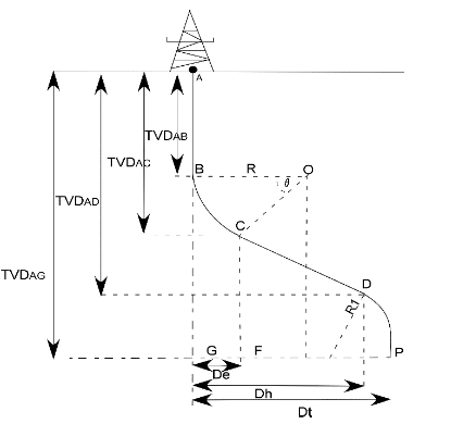
The Figure below shows a build-and-hold wellbore trajectory with the following target data :
- TVDAG : (KBTVD) of the target
- Dh: The target horizontal departure (point D).
- TVDAB: The kick-off point KBTVD
- q: build-up rate (In degrees per unit length).

Where:
- KBTVD AB: Distance from the surface location to the KOP;
- B-D: Distance from KOP to the bottom of the hole;
- Dh: Deviation of the wellbore from the vertical (Horizontal displacement);
- KBTVD AG: True vertical Depth;
- MD (A-D): Well-measured depth; and
- q: Build-up rate (°/30 m).
For the following formula, note that.
KBTVD3 =TVDAG, KBTVD2 =TVDAC, KBTVD1 =TVDAB.
1) The radius of curvature, R:

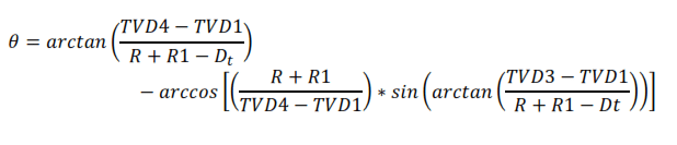
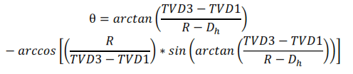
2) Maximum inclination angle, θ:

The angle τ can be found by considering the triangle OPD, where (case R ˃ Dh):

Angle Ω can be found by considering ODC, where:

Substituting OP into Equation 4 gives:

Now you can calculate the Maximum inclination angle, θ. The maximum inclination angle, θ, for the build-and-hold case where Dh is less than R, is:
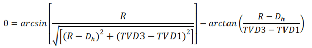
OR
3) Measured Depth of the wellbore target (MD)
The length of the arc, section BC, is:
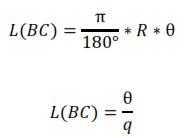
The length of the trajectory path CD can be determined from triangle DCO as:
The total measured depth, DM, for an actual vertical depth of TVD3 is:

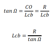
4) The horizontal departure GF (DE) at the end of the build can be determined by considering DCO, where:

To calculate the measured depth and horizontal departure at any point in the build section, consider the intermediate inclination angle θ’, the inclination angle at C,’ yielding a new horizontal departure, Dn.
Build Up, Hold, and Drop Off
Well Trajectory Calculations
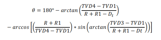
The second type of trajectory calculation is for an S-shape curve, which is shown above; there are two cases:
- R less than Dh and R+R1 more than Dt
- R is less than Dh, and R+R1 is less than Dt.
Typically, the maximum inclination is reduced to zero at Dt with drop radius R1, derived in the same manner as the build radius, R.
- KBTVD BG: Distance from the surface location to the KOP;
- KBTVD AG: True vertical Depth of well (KBTVD);
- B-D: Distance from KOP to the bottom of the hole (MD);
- G-D: Deviation of the wellbore from the vertical to the end of the tangent section;
- G-P: Deviation of the wellbore from the vertical to the end of the drop section;
- A-G: True vertical Depth;
- A-P: Measured Depth and
- D: End of tangent section
The following equations are used to calculate the maximum inclination angles for R+R1 more than Dt and R+R1 less than Dt: