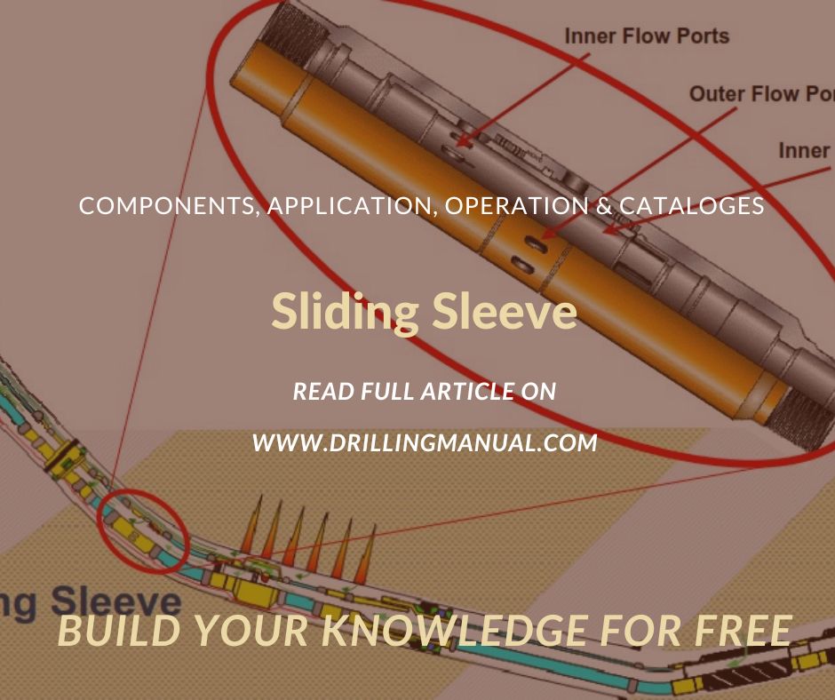
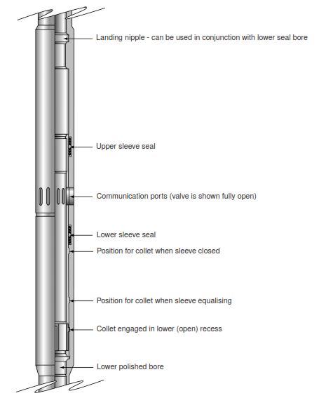
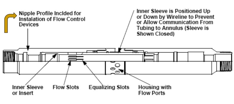
Sliding sleeves – sometimes called sliding side doors (SSDs) – are manipulated by wireline locks and use nipple profiles. The figure below shows a typical siding sleeve. This sleeve uses a collet to ‘hold’ the sleeve in one of three positions (open, equalizing, and closed). Sliding sleeves have earned a poor reputation – they either fail to open or close. Scale, asphaltene, solid debris, or erosion are the leading causes of these problems. Indeed, producing at high rates or through small ports can cause problems, as can trying to open or close a sleeve at high angles or with considerable differential pressures. Sliding sleeves form the basis of modern surface-controlled downhole flow control.
Components
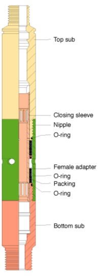
SSDs generally consist of a top sub, bottom sub, outer housing, and a sliding sleeve, hence, the title. There are two sets of packing at each side of the circulation holes in the outer housing, which seal off the flow path when the sleeve is in the closed position. When the sleeve moves to the open position by wireline or coiled tubing, a set of slots in the sleeve move across between the packings opposite the holes in the outer housing, hence providing a flow path.
The sleeve must be fully open before circulating; otherwise, there will be damage in the packing opposite the slots. Usually, the SSD will have an equalizing port to equalize differential pressure before the slots move past the packing.
Various models are available that open with upward or downward sleeve movement. We can install several SSDs in the completion string and selectively open or close them using the appropriate selective wireline shifting tool.
It is a must to equalize TBG and annulus pressures before opening an SSD sleeve to prevent blowing up or down the wireline tools in the tubing.
Operations
A differential pressure sufficient to overcome piston and sleeve friction is mandatory to open or close the sleeve. As the piston is balanced, the required surface pressure to open or close a valve is this pressure differential (typically a few hundred psi when new). The required pressure may increase with scale, asphaltene, or other downhole deposits. However, the force applied to open or close the sleeve can be significant (typically more than 10,000 lb), depending on the piston area. This pressure may be enough to cut through these deposits but is not guaranteed.
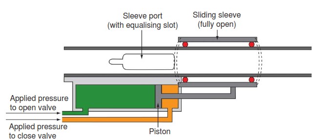
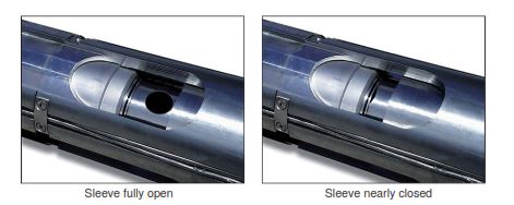
Figure 3 shows a hydraulic sleeve in the fully open and nearly closed position. If the hydraulics fail (leak or plug up), the valves will fail in the as-is position; they do not fail open or closed. If we cannot operate the valves remotely by the hydraulic system, we can use landing nipple profile and either slickline or coiled tubing as a backup. This backup system could be effective if the hydraulic system leaks. If there is plugging in hydraulics (e.g., debris in the control line), then a hydraulic lock will likely prevent movement of the sleeve regardless of the amount of jarring (Drilling Jars).
Within a sliding sleeve, a nipple profile is used to actuate (open or close) the sleeve. Even hydraulically operated sliding sleeves incorporate back-up actuation by wireline or coiled tubing and therefore often incorporate a landing nipple.
In this basic configuration, there will be a need of two control lines to control one valve.
Operations Of Multiple Sliding Sleeves
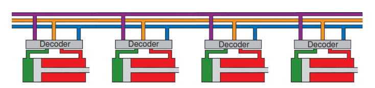
For multiple valves, it is possible to use a common line – typically the ‘pressure to close’ control line. You can see in figure 5, an example of configuration for four valves.

In the below example (Figure 6), if there is a need to open all the valves, apply pressure to the green, purple, blue, and orange lines but not to the red line. If we only need to open valves 2 and 4, then apply pressure to the purple and orange lines but not the green, blue or red lines. If there is a need to close all valves (for example, to pressure test the completion or set packers), pressurize only the red line. The control lines are typically integrated into the surface or subsea control system. We can then use the software to switch intervals open or closed. In some remote installations, there is merit in downhole flow control, but a control system or air may not be available. By using a manual hydraulic pump, we can operate the valves.
The limit for the number of control lines is usually the tubing hanger.
Operations While Stimulation
Workstrings or coiled tubing can efficiently operate sliding sleeves (the same trip as the excess proppant clean-out). Sliding sleeves can also be operated as part of a ‘smart’ well and cycled open and shut remotely to sequentially stimulate a well (Bellarby et al., 2003). This technique is more applicable to acid stimulation or proppant stimulations, where there is no need to clean the proppant after each treatment.
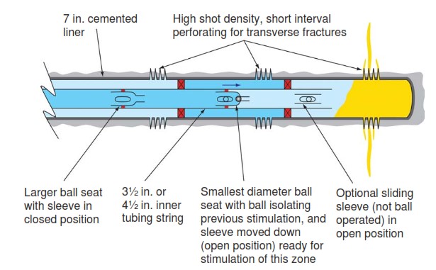
Some systems incorporate a ball seat in the sliding sleeve to hydraulically isolate the treated intervals underneath and open the sleeve. Seats (and balls) get progressively smaller further down the well, and some systems allow treating up to 10 zones sequentially. Such systems minimize the number of trips in the hole, but only if there is no need for cleaning out proppant between intervals. It is possible to pump multiple fractures treatments without stopping (dropping the ball on the fly), but this increases the consequences of a premature screen-out. The figure below shows an example of ball-operated sliding sleeves.
Sliding Sleeve Applications
We generally install a sliding side door (SSD) or sliding sleeve in the tubing string during well completion. Its main application is to deliver communication between the TBG and the annulus when we choose to open. It also has other applications:
- Kill a well before POOH with TBG during a workover operation.
- Bring a well onto production after drilling or workover by unloading (i.e., circulating the completion fluid in the TBG out with a lighter fluid),
- Allow selective zone production & testing in multiple zones well completion.
- In gas lift completion
- Landing a blanking plug in the nipple profile to shut in well or when testing tubing.
- Circulating inhibitors for corrosion control.
- As a contingency to equalize pressure across a deep set of packers.
Oil/Gas and Water Injection Wells
Below we have detailed the use of SSDs in single/dual completions.
Above packer for:
- Circulation purposes.
- Equalizing tubing/annulus before changing gas lift valves.
Between packers for:
- Production purposes.
- Killing and stimulation purposes.
In tailpipes below the bottom packer for:
- Equalizing pressure should a plug get stuck (Pipe Sticking) in the bottom no-go nipple.
- Production of a bottom interval if the no-go nipple is obstructed.
- Use of this application is rare.
Sliding Sleeve In Horizontal or High-Angle Wells
The SSD has had widespread use for zonal isolation between well packers in horizontal or high-angle wells. This benefit was an application of a standard completion tool operated by wireline methods converted into operation by coiled tubing to work in high well angles where wireline could not operate. One of the most significant users of this technology is Maersk Oil and Gas in Denmark.
Nice To Know
- We should space out SSDs, and other tubing string wireline operated completion components at least 10m (30 ft) apart to prevent accidental operation of the faulty component.
- Using an SSD above a production packer (Types of Packers) carries a risk as, historically, they have been a source of ‘A’ annulus leaks. New-generation SSDs with non-elastomeric seal technology have significantly reduced the risk of leakage, and we should now consider them more seriously for some applications.
- Should an SSD leak, a wireline set straddle can straddle it, but this reduces full bore access for wireline operations below this depth unless we retrieve the straddle.
- Other alternatives to SSDs have ported nipples with retrievable straddles.