Matrix acidizing is a stimulation treatment that places a reactive acid system into reservoir pore space while keeping injection conditions below the relevant formation-fracturing limit. Its purpose depends on the rock and the restriction. In sandstone, the target is commonly susceptible material impairing near-wellbore flow. In contrast, dissolution in carbonate rock can create channels that carry flow past a damaged region [1, page 3].
A useful treatment therefore needs more than an acid that dissolves a laboratory sample. The diagnosis must identify a worthwhile target, the fluid must remain compatible with the contacting system, and the delivery method must reach the intended interval. This guide connects those decisions with pressure accounting, treatment stages and performance evaluation [1, pages 103–110].
What Is Matrix Acidizing?
The word matrix describes the intended reservoir-flow regime. Treatment fluid enters the existing pore system rather than relying on the deliberate creation of a hydraulic fracture. Consequently, pressure control must consider conditions at the formation, not simply the pressure displayed at a surface pump. Existing fractures and variations in reservoir intake can still influence where the fluid goes [1, pages 3, 69, 96].
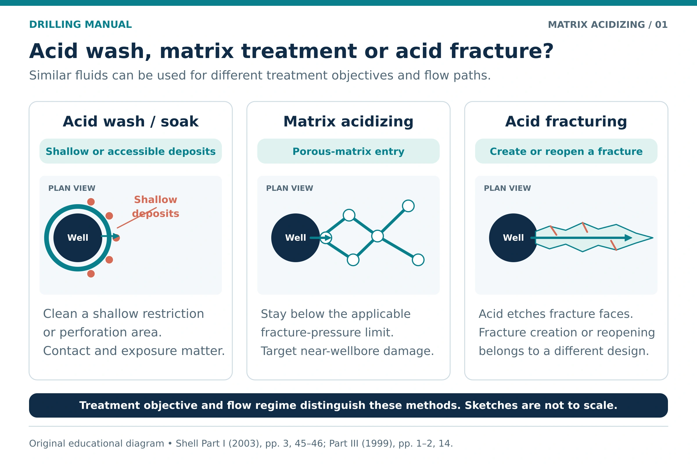
Matrix acidizing, acid washing and acid fracturing
These treatments can use acid, yet they address different flow paths. First identify the intended location and mechanism before comparing treatment names. The distinction also determines which pressure and placement questions the design must answer [1, pages 3, 45–46] [2, pages 1–2, 14].
| Treatment | Main objective | Defining consideration |
|---|---|---|
| Acid wash or soak | Clean accessible deposits, plugged perforations or very shallow impairment. | Local contact and cleanup; reservoir matrix stimulation is not established merely by putting acid in the well. |
| Matrix acidizing | Improve flow through the near-wellbore reservoir by treating suitable impairment or creating carbonate dissolution channels. | Place the treatment under the applicable non-fracturing conditions. |
| Acid fracturing | Create or reopen a fracture and use acid reaction to develop conductive etched paths, especially in reactive carbonate rock. | Fracture creation, growth, etching and subsequent conductivity require a different design. |
For the separate fracture-treatment subject, see the hydraulic fracturing guide. A matrix job that unintentionally opens a fracture has changed its flow regime; the original treatment label does not preserve the intended design conditions [2, pages 1–2].
Applications and Candidate Selection for Matrix Acidizing
Matrix acidizing can be considered when a producer or injector has a treatable restriction near the wellbore. Applications include appropriate impairment after reservoir drilling, completion or workover, and suitable restrictions that develop during production or injection. However, the reservoir must still offer useful performance after treatment [1, pages 5–6, 104–106].
| Situation | Evidence to establish | Question before selecting acid |
|---|---|---|
| Suspected damage after a well operation | Timing of the loss, contacting fluids, mineralogy and response tests. | Can the selected system address the actual impairment without creating another incompatibility? |
| Reduced producer inflow | Reservoir pressure, pressure/rate behavior, completion condition and plausible damage mechanism. | Is the restriction in the reservoir, or does tubing, lift equipment or completion geometry control output? |
| Reduced injection performance | Injection history, fluid quality, compatibility and the location of the restriction. | Will treatment reach the impaired interval and improve its useful intake? |
| Carbonate stimulation opportunity | Rock reactivity, reservoir potential, damage extent and feasible placement. | Can a designed dissolution pattern create useful communication beyond the impairment? |
Why positive skin is not a treatment instruction
Interpreted skin combines more than formation damage. For example, partial completion, perforations, gravel packing, deviation and other flow effects can contribute. Therefore, a positive total value does not identify a substance that acid will dissolve. Separate the contributions before estimating how much of the apparent loss the treatment could recover [1, pages 11–14].
Likewise, a well with low reservoir pressure or limited natural flow capacity may have little useful upside from removing a shallow restriction. Candidate screening should compare the present performance with a realistic post-treatment case, including the production system and the cost of obtaining that improvement [1, pages 5, 104–106].
Matrix Acidizing in Sandstone and Carbonate Reservoirs
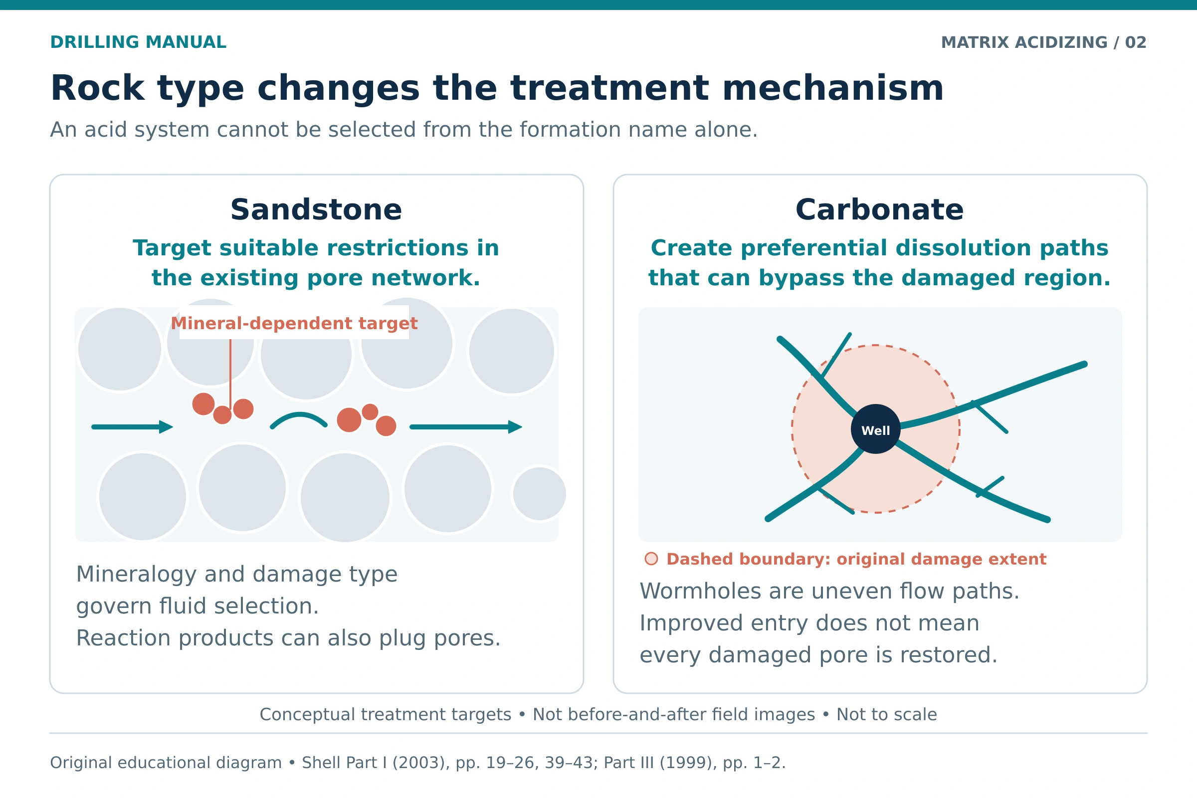
Sandstone: match the treatment to the impairment and minerals
Conventional sandstone matrix acidizing aims to recover flow capacity around the well. The relevant material may include acid-soluble constituents of mineral fines, residues or deposits, but its identity must be established. A sandstone description alone does not determine the fluid: clays, feldspars, carbonate cement and iron-bearing minerals can change the response [1, pages 19–25].
Hydrochloric acid, HCl, and systems containing hydrofluoric acid, HF, have different roles. HF can react with siliceous material, while HCl can address suitable carbonate material and contribute to a conditioning stage. However, the reaction sequence can also create poorly soluble products. The design must consider what remains after dissolution as well as what initially dissolves [1, pages 21–27].
As a result, increasing acid strength is not a general solution to poor sandstone response. An unsuitable formulation can promote precipitation, disturb sensitive minerals or weaken the rock. Laboratory comparisons should therefore use representative rock and fluids under relevant exposure conditions [1, pages 24–27, 81–87, 89].
Carbonate: develop useful dissolution channels
In carbonate formations, acid can dissolve the rock framework and develop preferential channels, commonly called wormholes. A useful channel can connect the well with less-impaired rock beyond the damaged region. Thus, improved flow may come from bypassing impairment rather than restoring every affected pore [1, pages 35, 37–42].
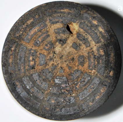
Photo: Czupski, Kasza and Leśniak (2020), Energies 13, 5940, Figure 13(a). CC BY 4.0. Inlet panel extracted from the published figure; pixel content unchanged.
The dissolution pattern depends on the interaction between fluid delivery and reaction. Rock composition, temperature, acid system and transport conditions all matter. Moreover, a favorable rate in a small core test cannot be transferred directly to an entire well interval: radial flow, leakoff and competition between channels change the problem at field scale [1, pages 37–42].
Factors Affecting Matrix Acidizing
The following factors connect the reservoir problem with fluid selection and delivery. They should be considered together, because a change that improves one part of the design can constrain another. For example, a fluid selected for reaction control also needs acceptable placement, compatibility and corrosion behavior [1, pages 25, 43–46, 69, 103–109].
| Factor | Effect on the design | Evidence to obtain |
|---|---|---|
| Damage type and location | Determines whether acid is relevant and where it must make contact. | Well history, samples, pressure/rate interpretation and response tests. |
| Mineralogy and rock fabric | Influences dissolution, reaction products, sensitivity and strength. | Representative mineral analysis and core observations. |
| Temperature and exposure | Affects spending, fluid behavior, compatibility and corrosion. | Relevant downhole conditions and anticipated contact duration. |
| Reservoir and fracturing pressures | Constrains the pressure available for matrix injection. | A consistent pressure basis and well-specific formation limits. |
| Fluid properties and intake | Controls pressure losses, transport and distribution. | Selected-fluid properties and a suitable injection model. |
| Completion geometry and heterogeneity | Influences access and preferential entry into parts of the interval. | Completion records, interval exposure and intake information. |
| Contacting fluids and materials | Can introduce precipitation, sludge, emulsion or equipment-compatibility problems. | Tests of the complete formulation, relevant mixtures and metallurgy. |
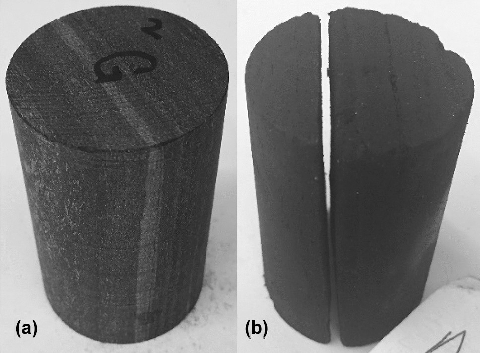
Photo: Rayan Khalil, Hossein Emadi and Faisal Altawati, original study (2021), Figure 4. CC BY 4.0. Image unchanged.
Fluid Selection and Matrix Acidizing Stages
Preflush, main treatment and overflush functions
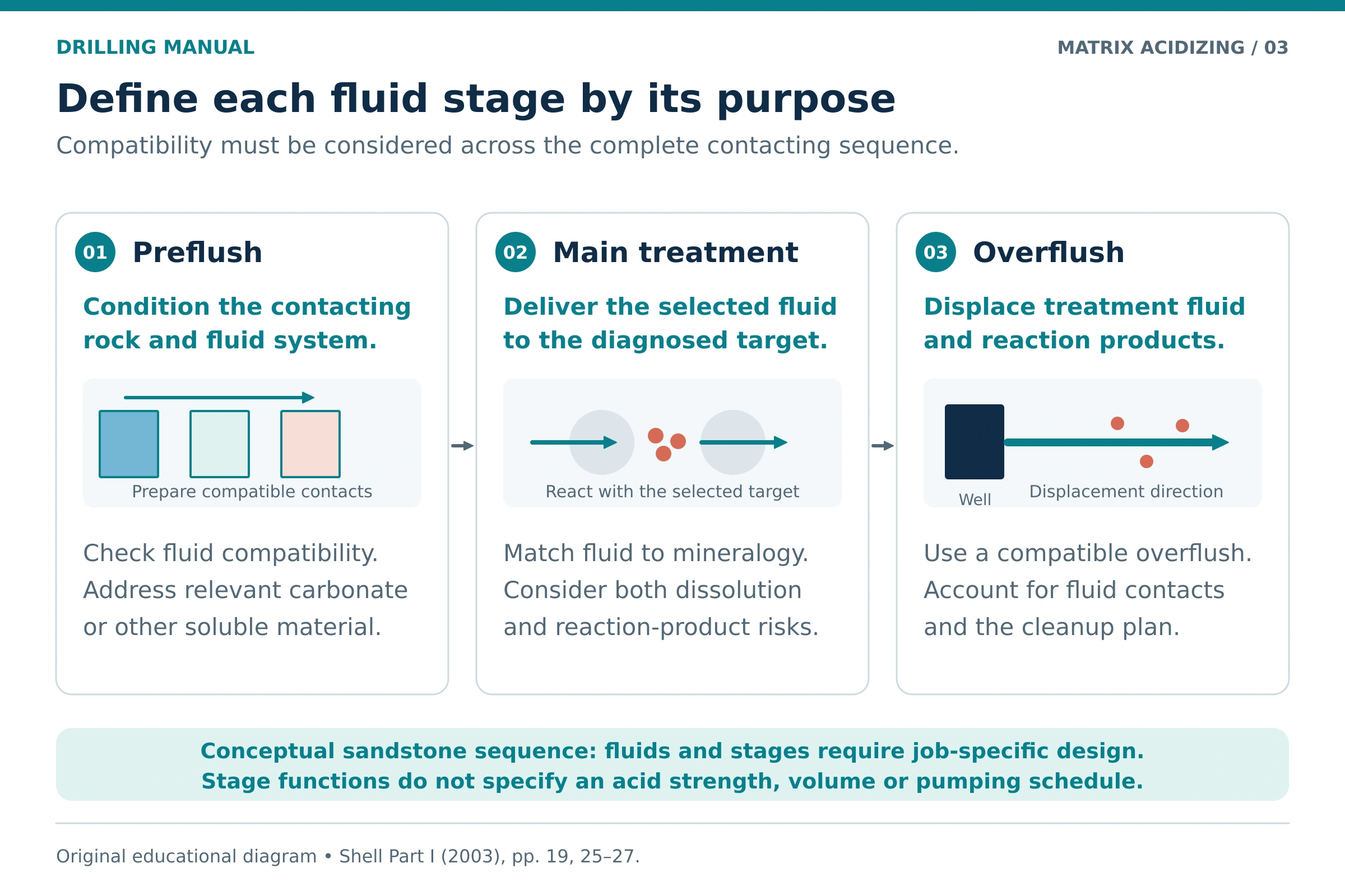
A conventional sandstone treatment may separate conditioning, reaction and displacement into different stages. This separation helps manage interactions along the fluid path. Nevertheless, the stage names describe functions; they do not establish a standard recipe for every sandstone or carbonate well [1, pages 19, 23, 25–27].
- Preflush or conditioning: prepare a compatible contacting environment and, where relevant, address carbonate material or fluid interactions that could interfere with the selected main treatment.
- Main treatment: place the chosen reactive system against the diagnosed target, with its spending behavior and potential secondary products considered.
- Overflush or afterflush: displace treatment fluid and reaction products away from the most critical near-wellbore region using a compatible fluid. The required displacement and subsequent cleanup remain design questions.
For example, the presence of carbonate minerals can affect an HF-based sandstone system even when the bulk rock is classified as sandstone. Consequently, mineralogy and compatibility tests should guide the sequence. A copied blend ratio or volume-per-foot value cannot resolve those interactions [1, pages 21–27].
Acid additives solve different problems
Corrosion inhibition, iron control and fluid-compatibility measures should not be treated as interchangeable. Corrosion protection concerns the metal exposed to acid. In contrast, iron-control chemistry concerns the behavior of dissolved iron as the fluid changes. Meanwhile, crude oil, brine and additive interactions can create separate sludge, emulsion or precipitation problems [1, pages 60–65].
Therefore, test the full formulation with relevant contacting fluids and materials. Check temperature, exposure time and additive interactions, rather than approving ingredients in isolation. Core-response work, corrosion tests and fluid-compatibility observations answer different questions, so a favorable result in one test does not replace the others [1, pages 81–87].
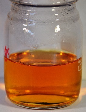
Photo: Czupski, Kasza and Leśniak (2020), Energies 13, 5940, Figure 10. CC BY 4.0. Photograph extracted from the published figure; pixel content unchanged.
Pressure Control: A Worked Matrix Acidizing Example
The formation responds to pressure at the treatment interval. For downward liquid injection, hydrostatic head raises pressure with depth, while flow losses reduce the pressure transmitted along the injection path. Consequently, comparing a wellhead gauge reading directly with a downhole fracturing value leaves out essential terms [3, page 18; derived pressure-balance illustration].
Define the pressure balance and its limits
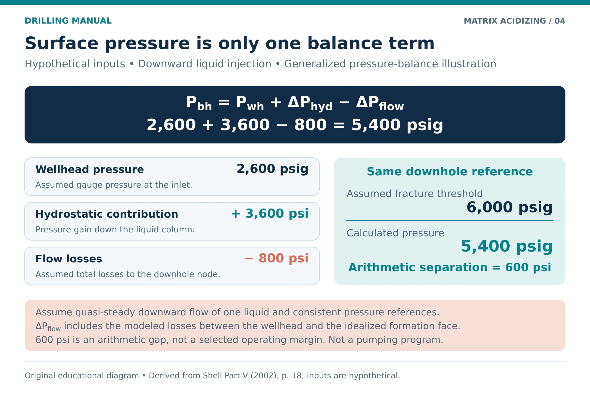
For this simplified example, define the downhole node at an idealized formation face. The educational balance below rearranges the downward-flow pressure terms used in the uploaded operational manual. It assumes one liquid and approximately steady conditions; acceleration, transient behavior and changing fluid distributions are outside this illustration [3, page 18].
- Pbh: pressure at the defined downhole node.
- Pwh: pressure at the wellhead, rather than an upstream pump gauge.
- ΔPhyd: positive hydrostatic contribution from the liquid column.
- ΔPflow: positive total pressure loss between those nodes, including the modeled friction and restrictions.
Hypothetical inputs and calculation
Assume the following inputs have been supplied for an educational case. The hydrostatic and loss terms are assumed values, not calculations for a particular well. Both pressure values use the same gauge reference, and the formation threshold refers to the same downhole node.
| Input | Assumed value |
|---|---|
| Wellhead pressure, Pwh | 2,600 psig |
| Hydrostatic contribution, ΔPhyd | 3,600 psi |
| Total flow loss, ΔPflow | 800 psi |
| Illustrative formation-fracturing threshold at the selected node | 6,000 psig |
Arithmetic separation from the assumed threshold = 6,000 − 5,400 = 600 psi.
The example shows the signs of the pressure terms and the importance of the measurement location. The 600 psi separation is not a recommended operating margin or proof that a treatment is feasible. A real design must establish formation limits, uncertainties, changing losses and the independent pressure limits of the well and equipment [1, pages 108–109, 129–130] [3, pages 17–18].
Matrix injectivity can change as a treatment progresses. Thus, an initial rate estimate should not become an unchanged instruction for the whole job. Permeability, viscosity, interval geometry, reservoir pressure and evolving skin affect the relationship between rate and pressure; a simplified single-liquid estimate also has limits in heterogeneous or multiphase conditions [1, pages 129–130].
Acid Placement and Diversion
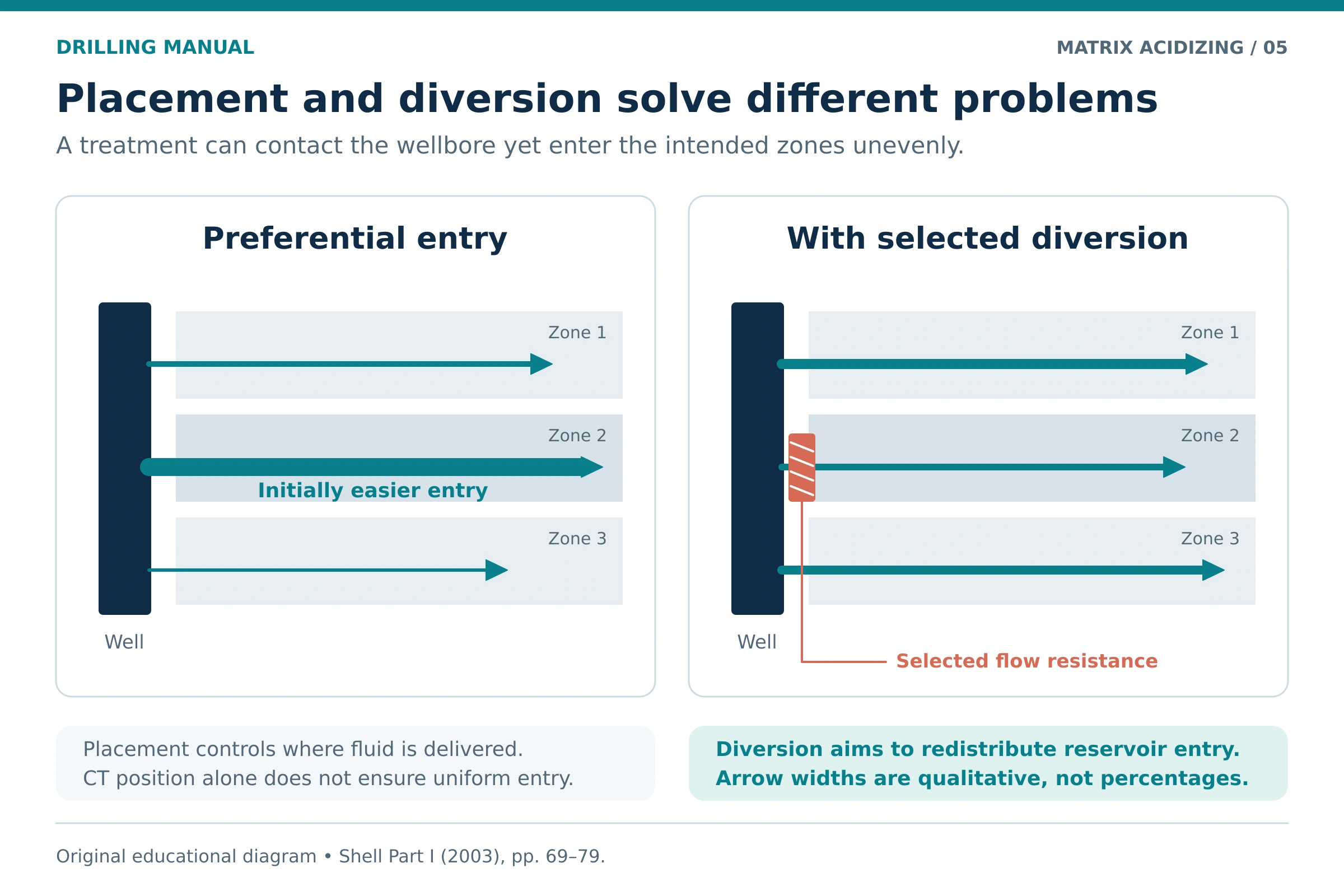
A well can accept the planned volume while leaving part of the target interval poorly treated. Fluid tends to favor easier-entry paths, and reaction can further improve those paths. Therefore, the placement design must address where the acid enters the reservoir, not only how much reaches the well [1, pages 32, 69, 107–109].
Delivery position and reservoir entry are different
Coiled tubing can position a delivery point along an interval. Mechanical isolation can also limit contact to a selected section when the completion and tools permit it. However, positioning an outlet does not itself demonstrate uniform intake into every layer; isolation or diversion may still be needed [1, pages 70–71, 107].
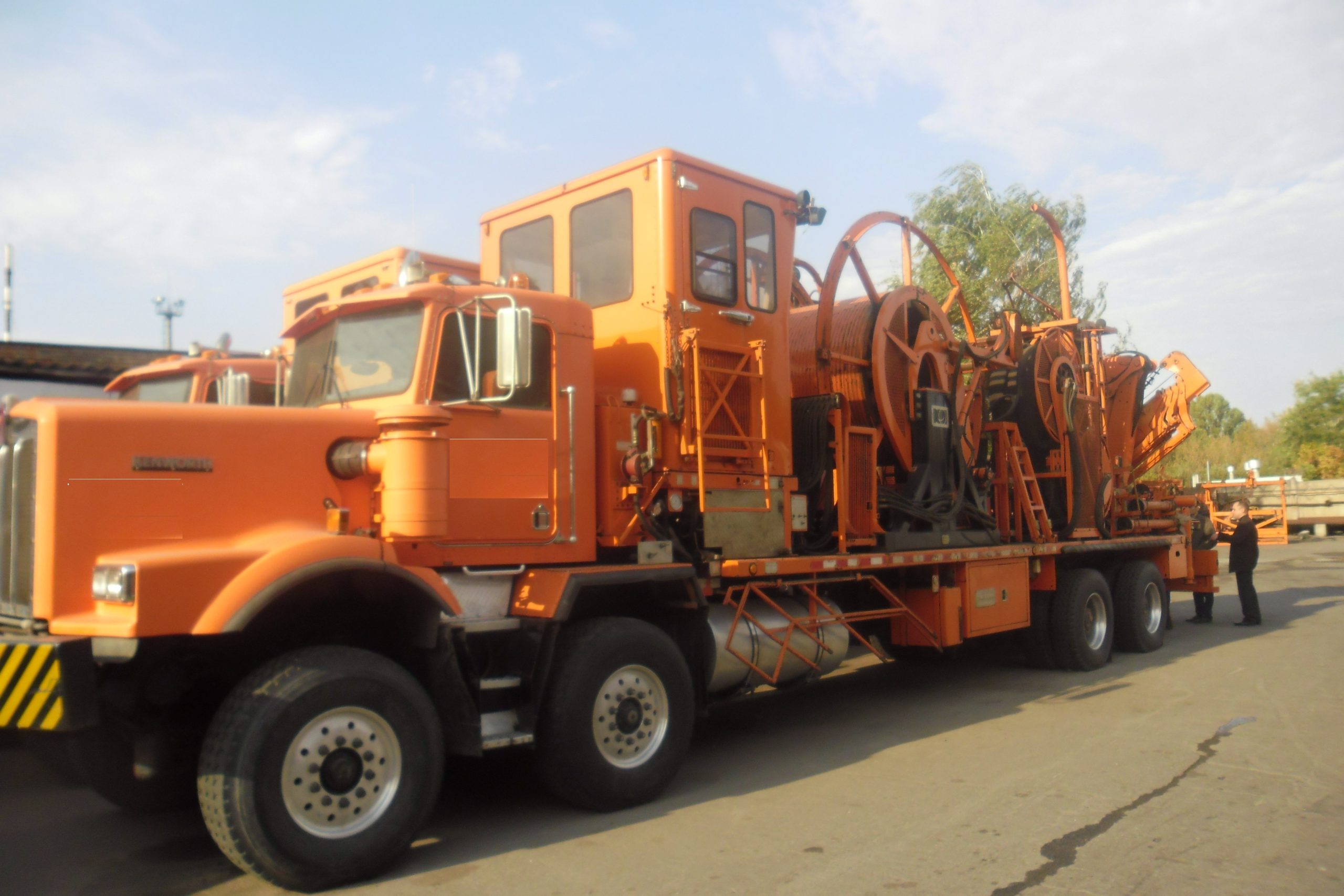
Photo: В.Білецький (2015), via Wikimedia Commons. Public domain.

For equipment background, see well packers. Access considerations differ between an open-hole completion and a cased interval connected through perforations. The treatment design must therefore use the actual completion configuration [1, pages 69–71, 103–109].
Diversion must include a cleanup plan
Diversion changes access or flow resistance so that a larger share of treatment can reach less-treated portions of the interval. Mechanical, particulate and fluid-based methods impose different constraints. In addition, a material that diverts successfully during injection may impair later flow if it persists or interacts poorly with the formation fluids [1, pages 69–77].
Consequently, choose diversion with its removal and post-treatment behavior in view. Temporary pressure response is useful evidence, but it does not provide a complete map of treatment coverage. Heterogeneity, completion geometry and the available measurements still limit the interpretation [1, pages 69–78, 107–110].
Planning and Monitoring Matrix Acidizing
A conceptual planning sequence starts with the performance problem and ends with a defined way to judge the result. The following steps organize the engineering review; the actual pumping schedule, operating limits and contingency actions belong to the well-specific program [1, pages 103–110].
- Define the target. Establish the restriction, its likely location and the recoverable performance.
- Check the contacting system. Review representative rock, reservoir fluids, wellbore fluids, metallurgy and the complete proposed formulation.
- Design placement. Identify the exposed interval, delivery method, expected intake distribution and any isolation or diversion requirement.
- Evaluate the pressure and rate conditions. Relate surface measurements to the formation node and assess the applicable equipment and formation constraints.
- Compare execution with the design. Record the actual fluids, stage volumes, rate/pressure history and placement or diversion changes so departures can be interpreted.
- Evaluate after cleanup. Compare the resulting well behavior with the earlier baseline and predicted response under meaningful conditions.
Fluid cleanliness and contact between stages also deserve attention. The site’s completion-fluid cleanliness tests provide supporting background, while fluid displacement and contamination control address the interfaces between well fluids. Acid-system compatibility still requires its own representative assessment [1, pages 81–87].
Evaluating Matrix Acidizing Results
Higher production is encouraging, but its cause still needs interpretation. For example, a change in drawdown, reservoir pressure, lift performance or test conditions can alter the rate. Compare the actual response with the treatment objective and use pressure/rate evidence alongside the job record and any suitable skin interpretation [1, pages 11–14, 110].
A simple rate-versus-drawdown comparison
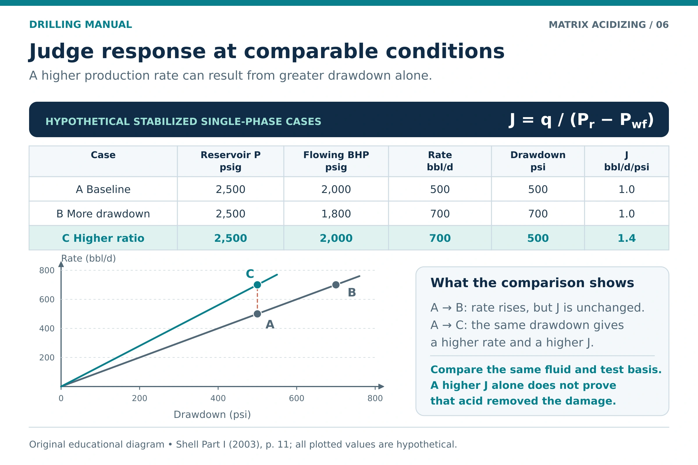
For a simplified stabilized single-phase liquid comparison, define an apparent productivity index as J = q / (pr − pwf). This follows the rate–drawdown proportionality in the source’s radial-flow model. The three cases below are original hypothetical inputs, with the same reservoir pressure and comparable fluid and test basis [1, page 11].
| Illustrative case | Reservoir pressure | Flowing bottomhole pressure | Rate | Drawdown | Apparent J |
|---|---|---|---|---|---|
| A: baseline | 2,500 psig | 2,000 psig | 500 bbl/day | 500 psi | 1.0 bbl/day/psi |
| B: greater drawdown | 2,500 psig | 1,800 psig | 700 bbl/day | 700 psi | 1.0 bbl/day/psi |
| C: improved ratio | 2,500 psig | 2,000 psig | 700 bbl/day | 500 psi | 1.4 bbl/day/psi |
Case B produces more because the assumed drawdown is larger; its ratio has not improved. Case C produces more at the same drawdown, giving a higher ratio. Even so, that observation alone does not isolate the mechanism responsible for the change. Gas, multiphase and transient tests need appropriate models rather than automatic use of this liquid comparison [1, pages 11–14, 110].
Limitations and Causes of Poor Results
Matrix acidizing has limited value when the chosen chemistry, target or access does not match the problem. For example, poor production caused mainly by depleted pressure, unsuitable completion geometry or a restriction elsewhere in the production system may persist after a technically effective near-wellbore treatment [1, pages 5, 104–106].
Furthermore, the treatment can introduce new impairment through precipitation, incompatible fluids, disturbed fines or retained diversion material. Rock-strength and corrosion constraints can also restrict the acceptable formulation and exposure. Therefore, laboratory dissolving ability must be considered alongside the complete reaction, placement and cleanup sequence [1, pages 22–27, 46, 60–65, 69–77, 89].
Nevertheless, uncertainty remains after testing. A core represents only part of the reservoir, while fluid distributions and pressure conditions change at well scale. Similarly, a post-treatment rate or skin estimate depends on the measurement and interpretation. A useful evaluation states what the evidence supports and identifies what remains unresolved [1, pages 11–14, 81–87, 110].
Practical Rules of Thumb for Matrix Acidizing
Use these qualitative principles to organize the design review. They do not supply an acid concentration, pump rate, treatment volume or pressure margin for a specific well [1, pages 19–27, 69–87, 103–110, 129–130].
- Locate the restriction before selecting chemistry. Reservoir impairment and a tubing or perforation deposit can need different treatment objectives.
- Estimate the removable part of the loss. Total skin is not a measure of acid-soluble material.
- Choose the formulation from the contacting system. Mineralogy, crude, brine, additives and metallurgy all matter.
- Give placement the same attention as reaction. Delivered volume does not prove that every target zone received useful treatment.
- Keep pressure comparisons at a defined downhole location. Include hydrostatic and flow-loss effects and use consistent references.
- Keep laboratory and field scales distinct. A core-test optimum or historical volume rule does not establish a universal field schedule.
- Design diversion and cleanup together. A temporary restriction must not become persistent impairment.
- Compare performance under meaningful conditions. Investigate the reason for a changed rate before attributing it to damage removal.
Matrix Acidizing: Frequently Asked Questions
Is matrix stimulation the same as matrix acidizing?
Matrix stimulation is the wider treatment category. Acidizing uses a reactive acid system, while other matrix treatments can use non-acid fluids for appropriate problems. Consequently, the diagnosis should establish whether acid is suitable before selecting an acidizing program [1, pages 3, 49–57].
Can the same acid system be used for sandstone and carbonate?
The rock label alone is insufficient, and the usual objectives differ. Sandstone treatment must account for its mineral assemblage and secondary reaction products. In contrast, carbonate treatment often seeks useful dissolution channels. Select and test the system against the specific rock, fluids and conditions [1, pages 19–27, 35–46].
Why is matrix acidizing kept below fracturing pressure?
Maintaining the intended matrix regime avoids deliberately creating or reopening a hydraulic fracture as the main treatment path. Once fracture flow becomes part of the design, placement, growth and conductivity require separate consideration. The relevant pressure comparison is at the formation [1, page 3] [2, pages 1–2, 14].
How much acid is needed?
There is no single volume that applies to every well. Instead, the answer depends on the target, rock and fluid response, exposed interval, penetration objective, delivery and coverage. Moreover, additional volume sent into an already receptive zone may not improve treatment of a less-receptive layer [1, pages 25–32, 69, 103–109].
Can matrix acidizing be performed through coiled tubing?
Yes, when the well and equipment design support that delivery method. CT can locate the outlet along an interval and can work with suitable isolation or diversion. However, outlet position alone does not demonstrate that acid entered all the intended reservoir layers [1, pages 70–71, 107].
Does a pressure drop during pumping prove successful stimulation?
No. Interpret the pressure history together with rate, fluid properties, placement changes and the evolving pressure-loss model. The job record and post-treatment tests are needed to judge whether the intended reservoir response occurred. A single surface trend therefore cannot establish the cause [1, pages 103–110] [3, pages 17–18].
Can acidizing make formation damage worse?
Yes. Unsuitable reactions, precipitates, incompatible fluid mixtures, disturbed fines or persistent diverters can add restrictions. Corrosion and rock-strength effects also require evaluation. This is why diagnosis, representative testing and placement planning are integral to the treatment choice [1, pages 22–27, 60–77, 89].
Does a higher production rate prove that the treatment worked?
A higher rate is an observation, not a complete diagnosis. Compare reservoir and flowing pressures, fluid conditions, completion changes and test behavior with the earlier baseline. The result should support the intended treatment objective, rather than simply reflect a larger drawdown [1, pages 11–14, 110].
References
The engineering discussion and original diagrams use the uploaded editions below. Numerical inputs in the worked examples are hypothetical. These dated references support the explanation; the article does not establish current operator requirements or a well-specific pumping program. Inline citations use printed page numbers; the references below also identify the corresponding PDF pages.
- Shell. Stimulation Field Guidelines, Part I (Revision): Matrix Treatments. EP 2003-5188, July 2003. Definition and candidate selection: printed pages 3–14 (PDF pages 12–23); sandstone treatments: pages 19–32 (PDF pages 28–41); carbonate concepts and acid wash: pages 35–46 (PDF pages 44–55); non-acid treatments and additives: pages 49–65 (PDF pages 58–74); placement and diversion: pages 69–78 (PDF pages 78–87); testing and limitations: pages 81–89 (PDF pages 90–98); naturally fractured formations: page 96 (PDF page 105); design and evaluation: pages 103–110 (PDF pages 112–119); matrix-rate assumptions: pages 129–130 (PDF pages 138–139).
- Shell. Stimulation Field Guidelines, Part III: Carbonate Stimulation. SIEP 99-5638, December 1999. Treatment definitions and acid fracturing: printed pages 1–2 and 14 (PDF pages 7–8 and 20).
- Shell. Stimulation Field Guidelines, Part V: Operational Aspects. EP 2002-5161, 2002. Operational constraints and pressure-loss terms: printed pages 17–18 (PDF pages 24–25). The source presents its treating-pressure equation in a fracturing discussion; the article explicitly rearranges the underlying pressure balance for a simplified educational injection example.
Related terminology: Matrix acidizing in the SLB Energy Glossary.