This Topic provides information on Coiled Tubing Pressure Control Equipment (surface ) commonly used to maintain the integrity of the well during CT operations (BOP) including Quad, and Combi types.
Coiled tubing well control equipment is designed to allow safe well intervention services to be performed under pressure. However, well pressure should be kept to a minimum to avoid unnecessary wear and tear on the equipment.
Well Control BOP & Pressure Control Equipment Configuration For Coiled Tubing
Well control equipment components should be installed, tested, and used to maintain control of the well at all times. Two barriers should be available at all stages of an operation to prevent the release of any hydrocarbon. To assure this the minimum well control stack shall include the following items, from top-down;
- One Dual Stripper type BOP (check also BOP stack) with lower stripper provided in conjunction with a pipe ram to provide two barriers in the event of the requirement to replace a leaking stripper, Primary control.
- One Blind ram BOP, including an equalizing valve across the rams.
- One Shear ram well control component could be combined with the Blind rams.
- One kill line and valves (2x).
- One Slip ram BOP.
- One Pipe ram BOP, including an equalizing valve across the rams.
Item (2), (3), (5) & (6) are Secondary control devices.
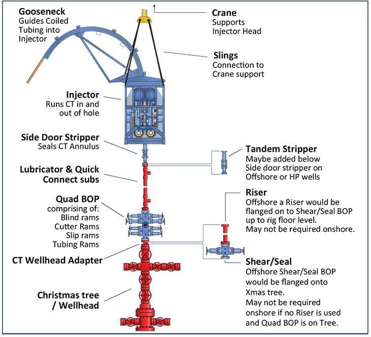
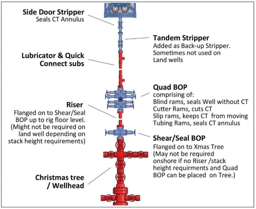
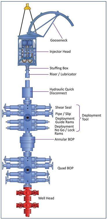
The actual configuration of the well control BOP stack will vary, depending on the maximum anticipated surface pressure (check also: MAASP calculations) and operations to be performed; see Figure 1 and Figure 2 for some possible combinations of well control equipment stack-ups. The well control components for C/T shall have a rated working pressure that exceeds the maximum anticipated surface pressure.
Starting from the top of the tree, a single cut/seal device should be a flange connected to the tree. However, this may not be required on land if the coiled tubing Quad BOP can be placed in close proximity to the Tree. The bore diameter and cutting capabilities of the shear/seal will depend largely on the type of tool string.
On top of the shear/seal is a crossover flanged drilling riser continuing to the rig floor, with any additional stack-up height that is required.
The coiled tubing BOP sits directly on the top of the riser with any crossovers that are required. This can either be a conventional quad BOP or a Quad with one of the newer style combi-BOPs. The combi’s are shorter and create less stick-up.
The stripper/packer or stuffing box is normally bolted to the underside of the injector head. A tandem stripper/packer can be run between the standard stripper/packer and the BOP. All connections between the wellhead and the nearest barrier device capable of forming a 100% blind seal should be flanged type.
Hydraulic connectors should only be used above the primary shear and seal BOP. The release mechanism should be designed so that:
- It cannot be activated when the connector is exposed to wellhead pressure.
- It remains latched by means of a simple pressure mechanical system.
- An indication device displays the latch status.
Primary Barrier external – Stripper Assembly
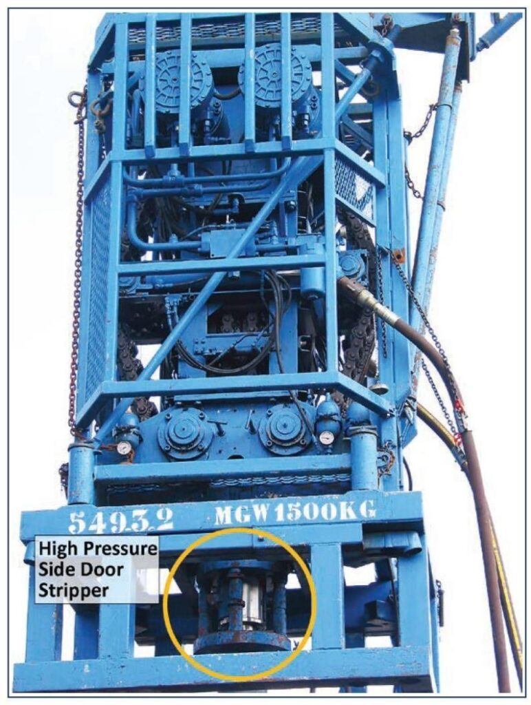
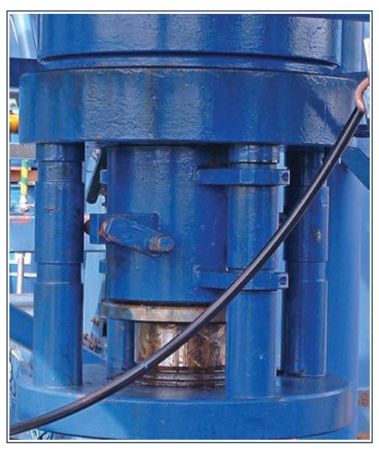
The stripper packer, or stuffing box, is the primary sealing mechanism for isolating wellbore pressure under static or dynamic operating conditions. It is assembled under the injector head (see Figure 3).
The principle of the 3 types discussed hereafter is the same, controlled hydraulic pressure acts on a piston that activates directly or indirectly the packing element which makes the seal. The life of a stripper insert, or packer, is dependent on:
- Wellhead pressure.
- Stripper pack-off pressure (force).
- The external condition of the pipe.
- Lubrication.
If the packer inserts wear, they can be replaced with or without C/T in the hole. In order to change the inserts with C/T in the hole, it is necessary to close the slip – and pipe rams and bleeding-off pressure below the stripper assembly. From the hereafter described stripper designs the conventional design can be the most difficult to change the insert in since it must be changed out from the top where the coiled tubing injector head is situated, thus limited access. The side door or radial designs allow access from the side of the stripper. The common standard maximum wellhead pressure under dynamic conditions is 24,130 kPa / 241 bar (3,500 psi) for a stripper packer.
Conventional Design
The conventional coiled tubing BOP stripper packer assembly, see Figure 4, uses a hydraulic piston operating from below, to compress a polyurethane element to create a seal around the outside of the C/T.
Wear bushings made of brass run above and below the sealing element to centralize the tubing before entering the packer insert. A Teflon non-extrusion ring above the packing element is required to minimize extrusion for maximum packer seal life.
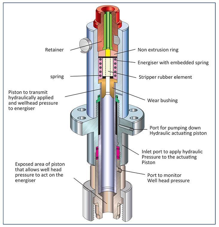
For changing out the packer insert and wear bushings with the C/T in situ, a split cap at the top of the stripper packer is removed allowing the consumable parts to be removed.
Side Door Stripper
The side door design of a stripper packer assembly has the following advantages over the conventional design:
- It reduces the distance between the packer and the injector chains, thus substantially reducing the length of unsupported C/T.
- It permits the replacement of the packer, energizer, and bushing from the open space below the injector, thus packer change-out is always easier, particularly when C/T is in the well.
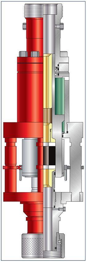
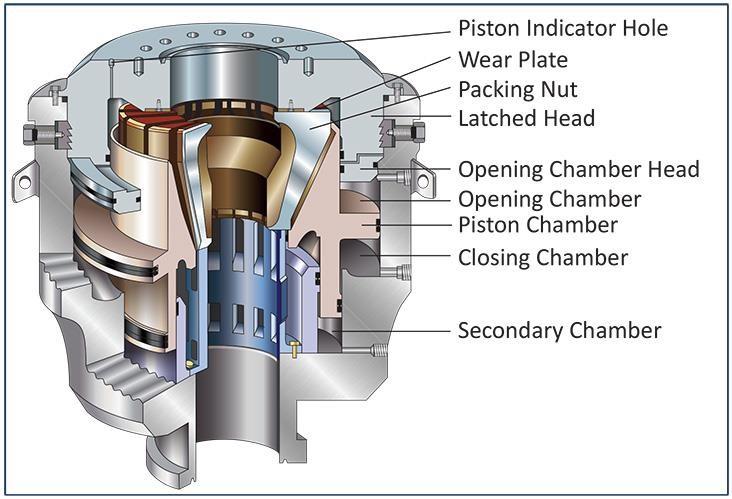
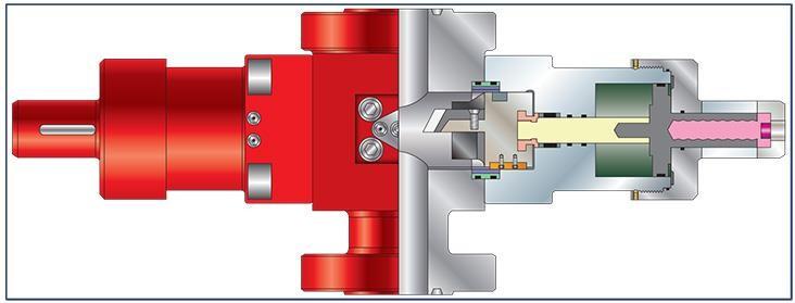
The side door stripper is more commonly used than the conventional assembly. The stripper assembly consists of a self-lubricating packing element that is energized from either above or below using hydraulic pressure. The operating concept is shown in Figure 6.
The side door stripper/packer is designed to pack off around coiled tubing being stripped in or out of the wellbore. The tool allows easy access to the packer, primary seal, and bushing. These can be replaced under pressure with the coiled tubing still in the well. The tool is installed above the coiled tubing BOP.
Well pressure is sealed-off by actuating the hydraulic cylinder to the extended position. This causes the packer cylinder sleeve to push against the packer. The packer is squeezed to form a seal around the tubing. Interchangeability of the bushing and packer allows one tool to be used with a wide range of coiled tubing sizes.
Tandem Stripper Packer System
The use of two stripper packer assemblies in one stack set-up of C/T well control equipment is increasingly used. The lower packer is not energized and therefore kept in reserve. Should the upper packer element, primary seal, become worn, then the lower packer element, secondary seal, can be energized. The operations can then either continue, utilizing the lower packer as the primary seal or the upper packer can be replaced and the lower packer de-energized and again held in reserve.
Radial Stripper
Because of the increased height due to using tandem stripper/packers, the radial stripper was introduced. The stack-up height is reduced by almost 50% and changing the packer is a very simple task.
The type of Stripper / Packer used will have a direct effect on the level of friction, and therefore, weight layoff seen during tripping. The wellhead pressure will also have a significant effect on the stripper friction force, such that the weight layoff for every well will be different. In the case of conventional or side door stuffing boxes, experience has shown that the side door type will exert a greater force for a given wellhead pressure. Other factors such as stripper elements and tubing lubricant will have a marked effect on the friction.
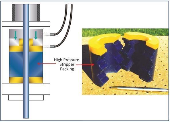
Stuffing boxes are operated from the control cabin and actuated by hydraulic pressure acting on a piston. The piston compresses a polyurethane element (stripper rubber) which makes a seal around the coiled tubing and allows the tubing to be tripped into and out of a live well with no leakage of wellhead pressure. Care needs to be exercised with the forces exerted by the stuffing box, so as not to contribute to the collapse of the tubing.
Stripper Elements
The different types of stripper elements are governed by their Schure hardness. Typically the low-pressure type is 75 Schure hardness (colored yellow) whilst the high pressure is 90 rated (colored orange). The efficiency of the stripper rubbers rests primarily on the lubrication medium used, and the impregnation in the stripper rubber to produce low friction properties.
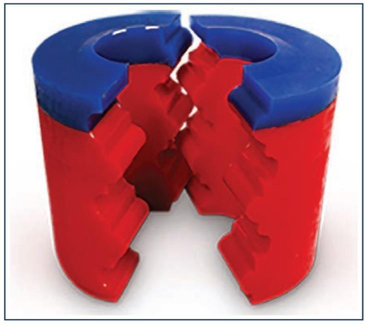
Note: Schure hardness is a rating system to determine the suitability of rubber to a pressure environment. The higher the number, the greater the hardness and the more suitable for use with higher pressures. The hardness rating system is used for ‘O’ rings, stripper rubbers, and packer elements.
The Stripper elements can be changed out during well operations. This involves closing the appropriate coiled tubing BOP Rams and ensuring pressure is bled from the system above the BOPs.
Lubricant
The method of lubricating the coiled tubing reel is not as important as the fluid used. It is essential that the correct type of lubrication oil is used so that friction is reduced to a minimum, thereby prolonging stripper rubber life. A popular fluid used was diesel oil, which initially will appear to lubricate and reduce friction efficiently. However, in the duration of the run into the hole, diesel will cause swelling and deterioration of the stripper rubber and cause added friction at the stuffing box. As a result, it is not recommended to use diesel as a lubricant. Century Oil 610T is a commonly used fluid with good lubricating properties.
Within the initial stages of any coiled tubing operation, high stripper friction will be experienced. The cause of this can be due to a number of factors, e.g. initial unlubricated pipe, bedding in of the strippers, etc. The value of friction will soon reduce and level out at a set rate usually beyond 150m (500 ft) into the well. Once this has occurred a simple calculation will determine the approximate stripper friction force which can then be used in computer simulator predictions to calculate the wellbore friction coefficient
Primary Barrier Internal – Check Valves
When using C/T on a live well it is standard practice to incorporate at least one but preferably two check valves, non-return valve, in the bottom hole assembly, and Primary barrier. Its function is to guard against a well blowout if the tubing leaks or parts at the surface by preventing flow back up the string. There are two forms of check valves commonly available, a Ball seat type and a Flapper type (see Figure 9).
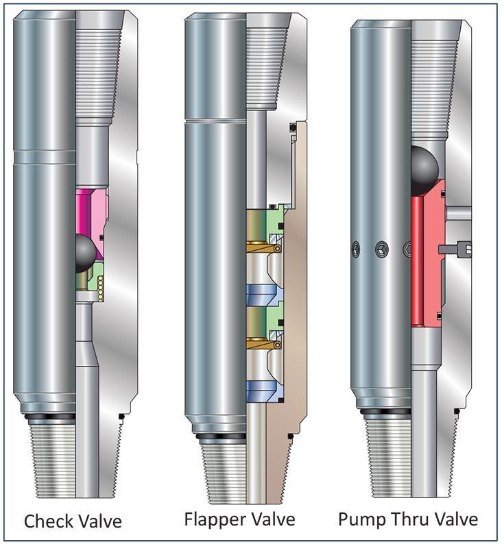
The Flapper valve is designed for use in conjunction with ball-operated tools because the dart-type valves will not allow the passage of a ball. Should a BHA become stuck, a ball can be pumped through to the flapper to operate the shear sub, while still providing a check valve protection for the C/T as it is retrieved from the well. Hence the flapper type valve is most commonly used and typically two valves are run in tandem or a dual flapper valve is used as a backup in case one flapper fails to seal.
Shear Subs
Although not strictly an item of primary well control equipment, the shear sub is almost always employed in the tool string as a safety device in case the BHA becomes stuck. There are two basic types:
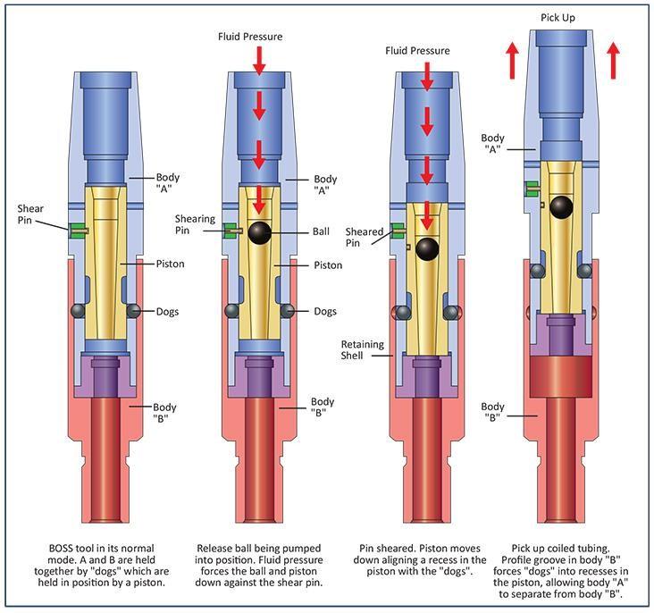
- Hydraulic Disconnect is often called a BOSS (Ball Operated Shear Sub) tool. The most common design is activated by dropping a ball into a seat at the top of the sub. Applying a determined pressure shear out a lock pin and moves an internal sleeve down to release retaining lugs. The two halves of the sub can then be separated, leaving a standard internal fishing neck looking up. This type of sub can be activated without dropping a ball but requires a much larger pressure because the surface area on which it is acting is smaller than when a ball is integrated. An alternative design utilizes the drop ball to divert applied pressure to a port above the ball seat in the sub-body. The pressure then acts across an internal sleeve, moving it downwards and allowing the retaining fingers to release. This type of sub can only be operated by dropping a ball.
- Tension Disconnect is often called a CTSRJ (Coiled Tubing Shear Release Joint) tool. These are simply two components pinned together such that they will separate upon application of a straight pull, leaving a standard fishing neck looking up. Although readily available, it is highly recommended that tension disconnect subs are not run because of the lack of control over downhole C/T forces and the consequent possibility of accidentally parting at the disconnect sub.
Downhole tools are available which will give high depth accuracy when running through-tubing tools. Tubing End Locators (TEL) and Tubing Nipple Locators (TNL) will show exactly where the end of the coil is with greater accuracy than the odometer in the control cabin. Both TEL and TNL require a BOSS tool above them in case their own shear mechanism fails and will possibly also have a BOSS tool below them for the through tubing tools.
Secondary Barriers – Coiled Tubing Blowout Preventers (BOPS)
The hydraulically operated coiled tubing BOP is the secondary safety apparatus (after the Stripper/ Packer) designed to prevent the uncontrolled release of wellbore fluids. The working pressure of all modern BOPs is 690 bar / 69,000 kPa (10,000 psi). As a failsafe, the BOP should only be operated with careful consideration and not used as a means of “parking” the tubing while at depth. They should be non-functional during well operations. It is normally fitted directly to the wellhead.
There are several makes and types of ram-type BOPs. They are basically of the same style and are either quadruple, triple, double, or single BOPs used in the same manner as all BOPs in drilling, workover, coil tubing, snubbing, and wireline operations.
C/T BOP’s are controlled from the operator’s panel and usually operated at 103 and 207 bar (1,500 and 3,000 psi) hydraulic operating pressure
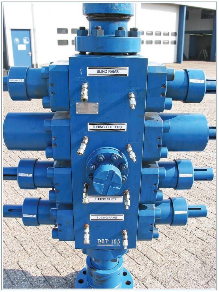
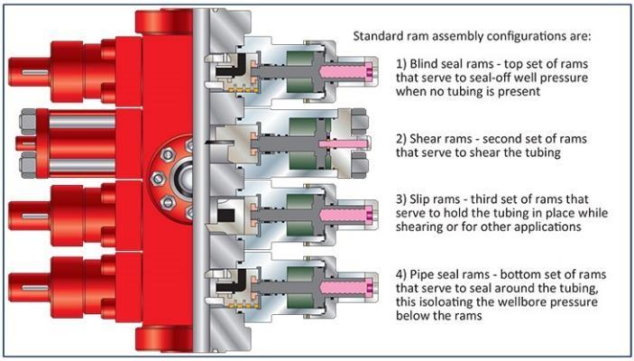
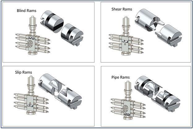
A Quad BOP, see Figure 11 & Figure 12, is the most commonly used BOP and has 4 pairs of ram actuators with the following functions (from top-down):
- Blind Rams: Used to seal the wellbore off at the surface when well control is lost. Sealing of the blind rams is achieved when the elastomeric elements in the rams are compressed against each other. For the blind rams to seal correctly and to avoid damage to the tubing, the tubing must be removed out of the BOPs first. The rams are designed to hold pressure from below first.
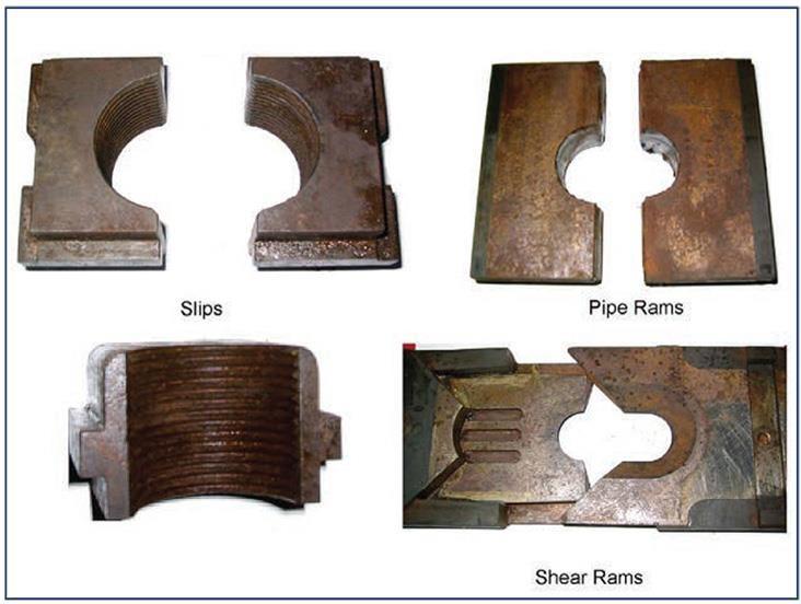
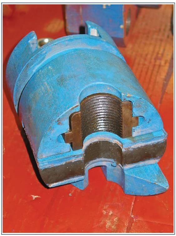
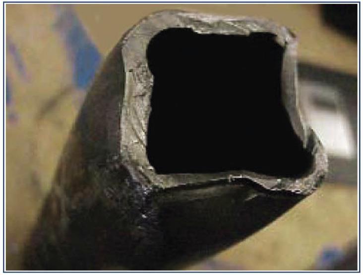
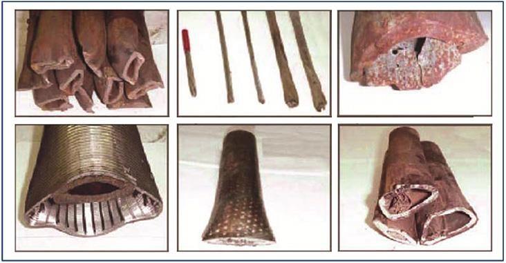
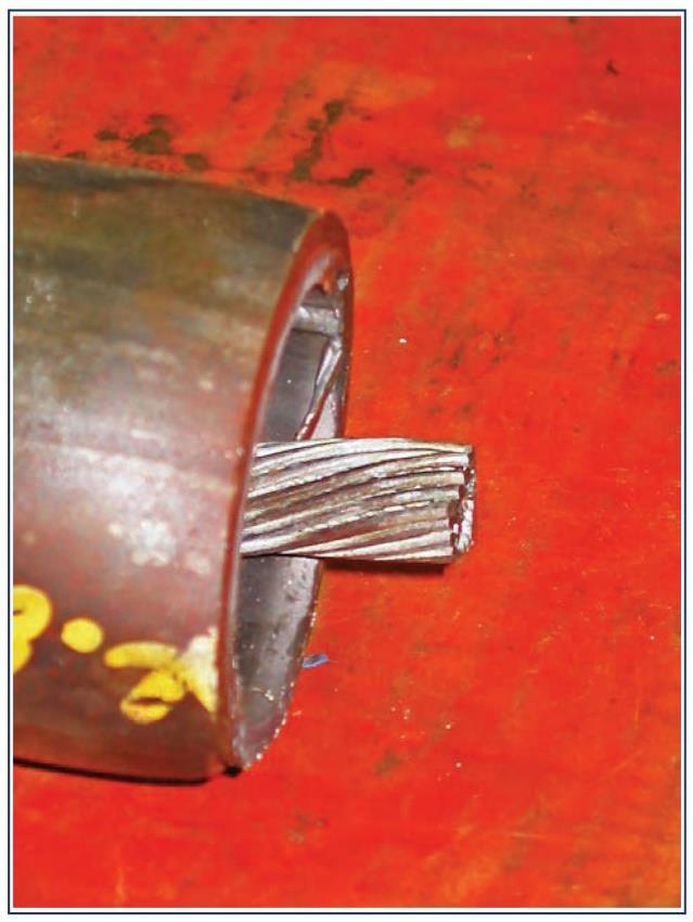
- Shear Rams: Used to cut the tubing in an emergency. Rams have replaceable blades specifically for C/T applications. As the searing plates are closed on the tubing, the forces imparted mechanically yield the body of the tube to failure. The cut will leave the tubing open-ended so circulation is still possible.
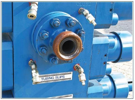
- Slip Rams: Designed to hold the tubing and prevent upward or downward movement. Rams have fixed-sized replaceable inserts for different tubing sizes. To prevent damage to the tubing by the slips, longer inserts are available, adding 75% to the contact area.
- In order to break up the stress risers, caused by circumferential slip marks, the teeth have vertical grooves cut to interrupt the slips marks on the tubing. Note: Slip rams should only be used when absolutely necessary. The extent of slip ram damage cannot be easily quantifiable by visual inspection.
- Pipe Rams: The pipe rams are equipped with elastomeric seals sized to the diameter of the tubing in use. When closed on the tubing they isolate the well annulus below the rams. Guide sleeves fitted to the ram assembly centralize the C/T as the rams close.
The blind and shear rams are separated from the slip rams by a flanged outlet in the BOP body which is used as a kill line during well control (see Figure 13). Returns from the well should either be taken via the Xmas tree or through a ‘Flow-tree’ mounted below the coiled tubing BOPs to avoid exposure of debris into the BOP cavities if returns are taken via the kill-line.
There may be up to three BOPs included in the wellhead hook-up (Quad, shear seal and annular BOP). A typical Pressure Control Stack up might include:
- Side Door Tubing Stripper / Packer
- Spacer Joint
- Tandem Side Door Tubing Stripper / Packer
- Spacer Joint
- Lubricator Sections
- Quick Latch Hydraulic Union
- Quad BOP
- Dual Combi BOP (Shear Seal)
- Tree Connection
The blind rams and pipe rams compartments of the Quad BOP stack are equipped with ports, which when activated, equalize pressure within the ram body. Since the rams are self-actuating, the pressure above or below must be equalized before they are opened. It is good practice to monitor the opening and closing hydraulic pressure when the system is activated. A high opening pressure could indicate that the riser pressure is not equalized. In this case, the ram-seals/packers could become damaged.
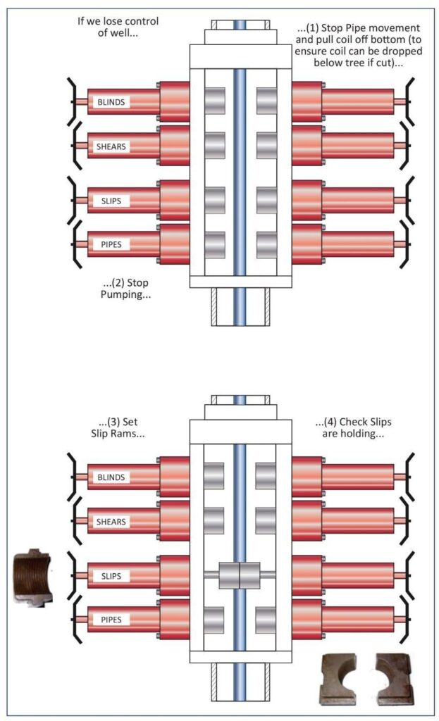
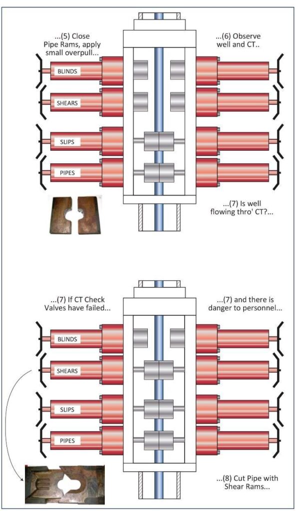
If during an emergency the tubing has to be cut, the order of operations should be:
- Close the Slip & Pipe rams.
- Cut the C/T with the shear rams.
- Using the injector, pull the remaining C/T above the Blind rams.
- Close the Blind rams.
Modern designs of shear-cutters do not completely crimp the tubing where it is cut, which allows monitoring and fluid to be pumped through the coil. Monitoring and circulation down the C/T is then possible via the kill-line into the cut-off end of the C/T, see Figure 17. Returns are taken via the wellhead or when available via the flow-tree.
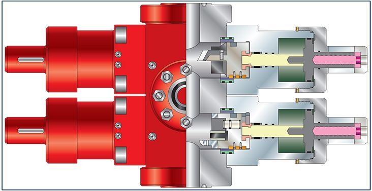
The Combi BOP, see Figure 18, has the same features as the Quad BOP, but combines the functions of the rams in one actuator:
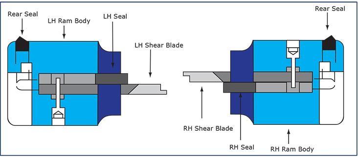
- Blind and Shear rams become a combination of Shear & Seal ram assembly.
- Slip and Pipe rams become a combination of Pipe & Slip ram assembly. Consequently, the Combi coiled tubing BOP has reduced height, weight, and lower hydraulic function requirements with respect to the Quad BOP. An advantage of the combined shear & seal rams is that the sheared tubing doesn’t need to be pulled above the blind rams before the well can be secured.
Triple BOPs are sometimes used and may be called Triple Combi BOPs. They can be set-up in various ways to suit the job. They are fitted with the standard Combi ram assembly’s configurations and a set of contingency rams, wireline rams, etc.
Secondary Barrier – Annular Coiled Tubing BOP
The C/T annular BOP is the most versatile piece of well control equipment, it’s designed to provide a seal around the outside of any piece of tubular with OD’s and shape of tubular, wireline and can even close on open hole, see Figure 20. Some types of annular preventers are pressure assisted from the wellhead pressure.
Separate Shear and Seal BOP
This item, sometimes referred to as the safety head, is rigged up directly onto the tree. It should always be considered especially when a live well situation could be induced as it protects the riser. It is essential for emergency shutdown situations, see Figure 21.
The latest type of Shear & Seal BOP is capable of shearing and sealing after cutting the following Figure 22:
- Coiled tubing
- Slickline
- Braided wire
- Sinker bar
- Drill pipe
- Conventional tubulars
- Bottom hole assemblies
Cutting capability for all components being deployed should always be confirmed
Should the stripper/packer elements lose sealing integrity, the blowout preventer tubing rams can be operated and the side door stripper can be redressed with new stripper elements with the tubing in the well, allowing live well operations to continue. Alternatively, many operations use two-side door strippers to provide the second barrier.
Note: A minimum of two barriers are required when changing out the stripper elements.
It is imperative that both sets of equipment, side door stripper and BOP, are properly tested before running the coiled tubing downhole. Most Quad BOPs are of the solid block type and are suitable for H2S service. Typically, 2 1∕2″ or 3″ BOPs are used depending on the coiled tubing size and that of the tool to be run. If a tool string is larger than 2 1∕2″ OD then it may be necessary to fit the BOP on top of a riser. This poses certain safety concerns as it may place the BOP out of easy reach in the event of an emergency where the manual operation may be required. Full bore, 3″ ID BOPs (or larger) are available to overcome this problem. The Table illustrates typical 2.5″ and 3″ BOP configurations.
| BOP Bore Size | Coiled Tubing Size | Pressure Rating | Test Pressure |
| 2.5″ | 1″ | 345 bar (5,000 psi) | 517 bar (7,500 psi) |
2.5″ | 1.25″ | 690 bar (10,000 psi) | 1034 bar (15,000 psi) |
| 2.5″ | 1.5″ | 690 bar (10,000 psi) | 1034 bar (15,000 psi) |
2.5″ | 1.75″ | 690 bar (10,000 psi) | 1034 bar (15,000 psi) |
| 2.5″ | 2″ | 690 bar (10,000 psi) | 1034 bar (15,000 psi) |
3″ | 2.375″ | 690 bar (10,000 psi) | 1034 bar (15,000 psi) |
| 3″ | 2.875″ | 690 bar (10,000 psi) | 1034 bar (15,000 psi) |
Note: BOPs for 1.25″, 1.5″ and 1.75″ coiled tubing are also available in 3″ and 4 1∕16″ bore sizes. These all have a working pressure rating of 690 bar (10,000 psi) and a test pressure of 1034 bar (15,000 psi).
Risers and Connections
Risers are part of the pressure control equipment in that they contain wellbore fluids/gases and pressure. Risers with wireline type quick unions, or occasionally flanged type connections are used for C/T work. The BOPs, etc. can be fitted with either type of connector although quick unions are more common. Connections between the wellhead and the shear & seal BOP, tertiary barrier, should be a flanged type connection.
Hydraulic connectors are becoming more commonly used as means of a quick and safe disconnecting system to remove the injector head for handling a BHA. The release mechanism should be designed so that:
- It cannot be activated when the connector is exposed to wellhead pressure.
- It remains latched by means of a simple pressure mechanical system. An indication device displays the latch status.
Deployment Systems
Novel deployment systems have been developed for the deployment of extra-long tool strings such as Tubing Conveyed Perforating TCP-type perforations guns. These systems provide barrier protection when the tool string is being made up and lubricated into the well.
Presently there are several systems on the market to deploy equipment. Although the details are different, the principles remain the same. A multi ram BOP system is located below the Quad or Combi BOP at such a distance that individual sections of fixed length can be snubbed in the well. Lastly, the C/T will be connected and the injector head installed to run the BHA in the hole. To remove the BHA, the procedure will be reversed.
For deploying long BHAs in a standard well control stack-up, using wireline and associated equipment could be considered as an option.
Support Frames
The injector head and BOPs are fairly heavy items at some distance above the Xmas tree. To avoid bending stresses on the connections and the wellhead, these items should be supported by a frame that transfers the load to a solid base, surface. Occasionally support can be done by a crane. If during the operations large volumes of cold fluids are pumped, shrinkage of the well could occur. Thus, monitoring load cells of excess loads to the surface and the support frame is essential to prevent collapse. Same counts for the crane, crane load to be continuously monitored.
Hydraulic Control System
A large volume of hydraulic operating fluid, stored under high pressure in the BOP accumulator, delivers the hydraulic energy required to close and open the BOPs and the remotely operated valves.
The hydraulic BOP operating unit also called the hydraulic BOP control system should be located in a safe place and:
- Should be provided with a control manifold, rated for 207 bar (3,000 psi) WP, which clearly shows “open” and “closed” positions for preventer(s) and remotely operated choke line valve.
- Should be provided with electrically and air-driven high-pressure pumps which automatically charge the accumulator bottles to the pre-set pressure. The electric pump should be fitted with an electric pressure switch, which automatically stops the electric pump when the accumulator pressure reaches 207 bar (3,000 psi) and starts the pump again when the pressure drops to 190 bar (2,750 psi) or below. The air-driven pump should be fitted with an air pressure switch, which automatically stops the air-driven pump when the manifold pressure reaches 207 bar (3,000 psi) and starts the pump again when the pressure drops to 186 bar (2,700 psi) or below.
- Preferably use high-pressure control hoses with a working pressure of 207 bar (3,000 psi), although steel pipe and joints are acceptable. The connections between the hydraulic unit and the preventers should consist of HP fire-resistant hoses or steel pipes and joints.
- Should allow all master and remote operating panel handles to be free to move into either position at all times, i.e. the shear ram operating handles should not be locked (but should be protected from inadvertent operation).
- Should have all spare operating lines and connections, which are not used in the system, properly blocked off.
- The hydraulic energy required to operate the BOPs is stored in a number of accumulator bottles which contain either a bladder-type diaphragm or a piston-type to separate the nitrogen from the hydraulic fluid.
- Without recharging, the accumulator capacity shall be adequate for closing and opening all preventers and closing again all ram-type preventers (as per API RP 5C7), and holding them closed against the rated working pressures of the preventers (or the highest anticipated surface pressure, whichever value prevails). The required accumulator capacity can be calculated from the total usable fluid volume used to carry out the above-mentioned opening/closing functions, thereby not dropping the operating pressure below the recommended minimum value. The total usable fluid volume is based on Boyle’s law.
Combinations of Stack-Ups with Primary, Secondary Well Control Equipment
Figure 25 illustrates a number of different options for the stack-up of a C/T Well Control rig-up.
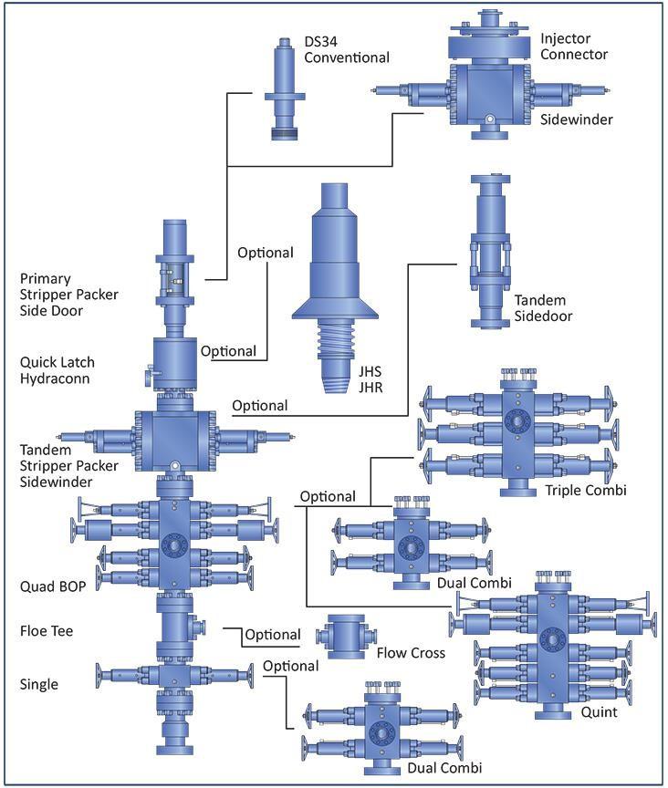
NOTE: Always refer to the Pressure Control Manual for the latest requirements
Outline Coiled Tubing BOP Operation
As stated the BOP rams in a Quad system are typical:
- Blind Rams
- Shear Rams
- Slip Rams
- Pipe Rams
The rams are in this order for a reason. Should there be an emergency situation where the tubing has to be cut, a simplified order of the operation would be as follows:
- Close Slip and Pipe Rams
- Apply slight overpull
- Cut Pipe with Shear Rams
- Using the injector, pull tubing clear from the Blind Rams and close
- There is a circulation port (2″ connection) between the Shears and the Slip Rams where circulation can be achieved by entering the hanging coiled tubing, should well kill be required.
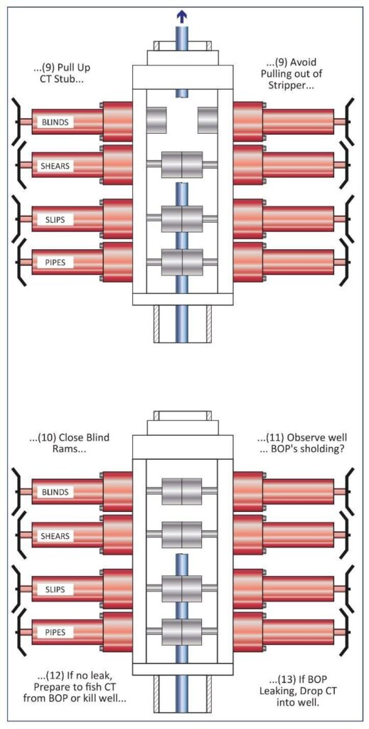
The sequence can be illustrated in more detail as follows:
Learning Summary
Having completed this topic, you must now be able to:
- Detail the operation of the “stuffing box / stripper-packer” system.
- List and describe the typical components in a Quad BOP arrangement.• Describe in detail, a shut-in sequence for a Quad BOP, to cut Coiled Tubing.
Very good Information. Could be interesting that be published like a manual, and only download
in addition, also pressure test procedure