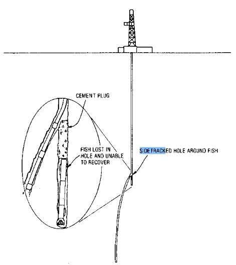
Sidetracking for oil wells is drilling a hole around unrecoverable junk, such as a stuck drill string ( Check also Pipe Sticking problem); it is necessary to place a cement plug above the junk at a required depth that will allow sufficient distance to kick off the cement plug and drill around, bypassing, the original hole and junk (junk mill). Drilling experts recommend high-density cement plugs for this application.
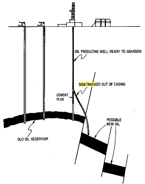
In other words, oil/ Gas Wells may require sidetracking to redrill the well to a new target, maybe to pass a fish or because of hole problems. To sidetrack any Oil / Gas well, you must develop a lateral force to allow the drilling bit to cut on the side of the hole. The drilling BHA geometry will provide this force.
Problems That May Occur During Sidetrack Drilling Well.
- The most common is a failure to deviate because the plug is too soft. We can correct it by setting a more extended plug and dressing it off correctly.
- Drilling around the plug and back into the original hole, especially. This is a less common problem in soft formations. In addition, we may correct it by setting a more extended plug and sidetracking with a higher build angle.
- Hard formations may cause particular sidetracking problems, especially with soft plugs and sometimes even good, hard plugs. Some formations are harder than the cement plug, so the drilling bit (also check: types of drilling bits) will preferentially drill the plug. It is possible to correct it by setting the hardest plug possible. It is possible to use a more extended plug so there is more distance for sidetracking. Drilling with reduced weight or possibly “time drilling” with an aggressive deviation assembly is also helpful.
- Sidetracking in holes containing oil-based mud reportedly causes problems. Still, it shouldn’t if the plug slurry is designed and positioned correctly using adequate spacers. Other remedies include setting a longer plug with extra slurry and using a higher sand content.
Sidetrack Drilling Failure
The main reason for failure to sidetrack successfully (with one plug) is drilling before the slurry hardens appropriately. Other causes include using a slurry volume (also check: casing cement slurry volume calculation) that is too small so that the plug is too short, contaminating the slurry during placement, and not deviating the hole aggressively during kickoff. The underlying reason may be a failure to design a suitable slurry. It is essential to be patient. One can always consider using cement slurry accelerators. Still, omitting cement retarders is preferable, if possible, or using only the minimum amount. Most failures require plugging back and sidetracking a second time, an additional and usually unnecessary expense.
It is familiar to locate the horizontal position of the kickoff point based on measurements taken during drilling. The alternatives are to measure with a wellbore surveyor and accept target limits within a cone of uncertainty. This is usually acceptable for sidetracking around a fish and large targets with few limiting hard lines. Remember, using one of the three measuring systems for measurement and orientation during sidetracking is a good practice.
Sidetrack Drilling In Open Hole
The sidetracking in the open hole is accomplished by setting a sidetracking cement plug and drilling the extra cement to the kickoff point. The concentric and parallel versions of the steering tool measuring system are described here for measurements and orientation.
Sidetracking Well Procedures Using Concentric Steering Tool
For the concentric steering tool measuring system, it is necessary first to build a sidetracking drilling mud motor assembly, similar to a deviating motor assembly, with a steering tool measurement sub.
Sidetrack Drilling Preparations
Sidetracking procedures will be as follows:
- Measure & record the toolface correction, which is the angular difference between the toolface and the indicating magnets.
- Lower the assembly to the top of the plug by tripping the pipe.
- Lower the instrument measurement package inside the drill pipe with a shielded electrical conduit (cable) on the drum of a winch on a cable truck.
- Set this instrument package in the measurement sub.
- Install a swiveling pressure pack-off on the drill pipe and connect it to the mud hose.
- Start the mud pump to circulate mud, which will rotate the drilling bit with a motor.
- Observe the direction of the toolface on the data display monitor. It is usual to set required corrections in the surface readout equipment so that it reads the corrected tool’s face direction. This usually includes the difference between the toolface, the indicating magnets, and the correction to true north.
- Turn the drill string to point the bit in the required direction and lock it to prevent it from rotating. Usually, locking the swivel on the traveling block can handle that.
- Drilling of the sidetrack hole begins by lowering the drill string slowly and applying weight to the bit, increasing the weight gradually until the weight is within the specifications of the motor and bit.
Note: It is essential to monitor the drift and direction of the hole and the toolface as drilling continues, orienting again as needed. This is accomplished by unlocking the swivel, turning the drill pipe in the correct direction, and locking the swivel to prevent the drill pipe from rotating. Drilling resumes.
Operations
- Record the precise measurements periodically by allowing the deviating tool to stop momentarily.
- The next step is to add 1-3 joints of drill pipe to the drill string when the top of the drill pipe is near the rotary.
- Stop the mud pump and disconnect the pack-off.
- Pull the instrument package out of the hole with the winch on the cable truck.
- Lower the instrument package into a joint of drill pipe in the mouse hole and connect the pack-off to the top of the joint.
- Lift the joint of the drill pipe out of the mouse hole, place another joint in the mouse hole, and connect it to the bottom of the first joint.
- Another joint of the drill pipe may be connected if there is sufficient mud hose length and space in the drilling rig mast.
- Lift these joints and connect them to the top of the drill string.
- Lower the instrument package inside the drill string with the cable and sit in the measurement sub.
Final Steps
- The pack-off is sealed, and the mud pump is started.
- The sidetracking assembly is oriented, the drill string is locked and sidetrack drilling resumes. If it is incorrect, the drift angle may be adjusted with different bit weights and rotational speeds.
- If necessary, it is possible to trip and change the bottom hole assembly as described for deviating in the open hole.
- The instrument package may be replaced if it fails by pulling it out of the hole from inside the drill string with the cable on the cable truck and lowering another instrument package into the hole.
- If the cable parts are damaged, they may be recovered by fishing or pulling the drill string.
- Drilling continues, sidetracking the original hole until the new deviated hole is in the correct direction with an established upward curvature. The final step is to drill directionally or horizontally by one of the procedure of deflecting tools.
Sidetracking Well Procedures Using Parallel Measuring Tool System
Sidetracking with the parallel measuring tool system is similar, except that the lower part of the cable holding the instrument package is inside the drill string, and the upper part is outside. The cable passes through a side-door sub inside the pipe to the outside.
The sub (Drilling Subs) contains a seal assembly for sealing around the cable and pumping drilling fluid through the drill string. Usually, the sub is positioned so that the e-line is outside the drill pipe in a vertical section of the cased hole. These limitations may be modified depending upon specific hole conditions.
Sidetracking Well Procedures Using Parallel Steering Tool Measuring System
For the parallel steering tool measuring system,
- The first step is to lower a sidetracking motor assembly with a steering tool measurement sub into the hole to the location for the installation of the side-door sub.
- The instrument package is lowered into the drill pipe and seated in the measurement sub.
- A side-door sub is connected in the drill string, the cable is passed through the sub, and it is sealed.
- The sidetrack assembly is lowered by tripping while simultaneously lowering the cable with the cable truck until the assembly is near the bottom of the hole.
- The Kelly is connected, and the mud pump is started.
- Orienting and sidetracking are similar to the sidetracking procedures with measurement instruments run in parallel systems.
- Standard drill pipe connections are made.
- The drill string and sidetracking assembly are pulled out of the hole, and the instrument package is replaced if it fails.
- Then, lower and orient the assembly, and sidetrack drilling begins as described.
- If the conductor line parts are either while drilling or tripping, the connected section is pulled out of the hole, sometimes while pulling the drill string and fishing when necessary.
- Drilling continues until the original hole is sidetracked with a new deviated hole drilled in the correct direction with an established upward curvature.
- Then, drilling continues directionally or horizontally.
Sidetracking Well Procedures Using Time Drilling
Some sidetracking plugs are too soft to sidetrack by the method described but may be sidetracked by time drilling. The procedure may also apply while sidetracking in very hard formations where the cement hardness is similar to or less than formation hardness.
- First, a deviation assembly is run with the maximum reasonable angle-build section.
- The top of the dressed-off plug is touched (tagged). The assembly is picked up until there is a small amount of bit weight on the plug, usually only noticeable on the sensitive needle or pointer of the weight indicator.
- The actual weight on the cement top should be negligible.
- The sidetracking assembly is oriented, and directional drilling begins.
- After about 5 to 20 minutes, the drill string is lowered a few inches while continuing to rotate the bit and circulate.
- The procedure continues until about 5-10 ft are drilled.
- It is essential to avoid using noticeable bit weight early in this procedure.
- The drilling penetration rate is about 2-4 ft/hr, depending upon the bit, plug hardness, and the formation.
- The next step is to begin increasing the bit weight very slowly.
- Typically, the drilling response will show if the bit is sidetracking correctly into the formation or following the old hole. If the procedure is successful, sidetracking continues. Otherwise, it is necessary to try it again.
- If the hole is not successfully sidetracked on the second try, the soft plug must be wholly drilled out and another set.
Sidetracking Cased Hole Wells
Cased holes are sidetracked by one of three methods, listed here in order of increasing risk:
- Sidetracking through a milled casing section.
- Whipstock through a milled casing section.
- Whipstock through a casing window.
Each has advantages and disadvantages. Measurements are recorded with one of the three measurement systems for orientation depending upon the type of sidetracking. The most applicable method is selected based on depth, casing size, hole condition, the reason for sidetracking, and operator preference. Here, we will discuss the operations through milled casing sections. In the article Whipstock Drilling, we shall cover the sidetracking by using whipstock.
What Is The Difference Between a Cased Hole And Open Hole Sidetrack Drilling
Sidetracking fundamentals in cased and open holes generally are similar. However, one significant difference is removing a section of casing by milling or milling a hole (also check: Milling In Drilling Operations) through the side of the casing. Other differences are the methods of plugging back, sidetracking procedures, and some of the tools. The cased wellbore is surveyed with a gyro survey tool to locate the position of the kickoff point if necessary. The cone of uncertainty may be used if it is applicable.
Sidetracking in cased holes is often a higher-risk operation than sidetracking in open holes. Smaller diameter casing (also check: casing design) requires smaller tools with less strength than larger ones. Operations are more complex in smaller holes. In addition, they usually take longer because of the involved procedures and the necessity of removing a casing section or milling a hole through it. The drill string may rub and wear against the milled hole through the casing and, in the worst case, become stuck (also check: Pipe sticking problem).
Sidetracking Through A Milled Casing Section
Sidetracking through a milled casing section is the most common procedure and involves the least risk. It is used for high and low build angles, long sections, and most other cases. It is a standard procedure for reentering an old vertical cased hole for drilling horizontally. The preferred casing size is seven in. or larger since more operating problems occur while sidetracking inside smaller casing sizes. Larger casing sizes may be necessary if the deviated hole section requires more than one casing pipe string (also check types of casing ). Any of the three measurement systems may be used.
Measurement-while-drilling (MWD) will be described here for illustration purposes. It is ordinary to plug the lower hole before milling the casing, depending upon the formation conditions exposed in the lower hole compared to those in the section where the casing will be removed. A drillable cement retainer is standard for plugging. The procedures will be as follows:
Setting The CMT Plug
- The first step is to connect the cement retainer to the bottom of the drill pipe and lower it into the hole to the location selected for plugging. This frequently is the same depth as the bottom of the sidetrack plug.
- Then, the retainer is set, and mud is pumped into the formation, ensuring the casing is open.
- The third step is to mix about 25 bbls of cement slurry and pump them into the drill pipe. Mud or water is pumped behind the slurry and displaced through the retainer into the casing below the retainer.
- A back pressure valve in the retainer seals and contains pressure below the retainer after pulling the drill pipe. The cement and retainer serve as a double plug. An alternative procedure is similar, except that about half the cement is displaced below the retainer.
- The next step is to pick up the drill pipe from the retainer and displace the remaining cement on top of the retainer. This ensures a seal with cement above and below the retainer.
- Then, the drill pipe is pulled out of the hole.
- The milling casing starts about 20 ft above the projected sidetrack depth. About 60-80 ft of the casing are milled and removed.
- A sidetracking cement plug is set as previously described.
- The bottom of the plug is placed at least 50-100 ft below the bottom of the milled casing section.
- The plug is extended through the milled section and into the upper casing.
- After it hardens, the excess cement is drilled or milled so that the top of the plug (kickoff point) is about 20 ft below the top of the milled section of the casing.
Sidetracking Process
Sidetracking is accomplished like sidetracking in the open hole, allowing for a different type of measuring system, measurement-while-drilling (MWD). A measurement or instrument sub holds the MWD equipment. The MWD measurement sub is connected to the sidetracking motor assembly.
- The next step is to measure and record the toolface correction, the angular difference between the toolface, and the indicating magnets.
- The assembly is then lowered into the hole. A mud pulse sensor or other sensing instrument is installed at the surface, depending upon the MWD system, and the data display monitor is also installed.
- The Kelly is connected to the drill string, and the mud pump starts circulating and rotating the bit.
- The direction of the toolface should be checked on the monitor. It is normal to set the corrections in the surface readout equipment for true north and the difference between the toolface and the indicating magnets so that it reads the corrected toolface. Orienting is done by turning the drill string to point the toolface in the correct direction.
- Then, the rotary is locked to prevent rotating the drill string.
- The swivel is locked on the traveling block if the Kelly is unused.
- The drill string is lowered slowly, and sidetrack drilling begins. Precise measurements are taken periodically for verification by allowing the drill string to stop immediately. The allowances for bit walk and reactive torque may be omitted since MWD equipment gives the correct direction of the toolface. The direction and orientation are monitored again by turning the drill string as required.
Final Steps
- The drill pipe connections are made in the usual manner.
- If it fails, POOH the drill string to replace the MWD equipment.
- It is possible to sidetrack a few cased holes to bypass an unrecoverable fish, and the lower part of the hole may be redrilled by blind sidetracking. This is used when it is not necessary to monitor and control the direction of the sidetracked hole.
- The inclination is still monitored, but sidetracking continues without directional control.
- Nonmagnetic collars are omitted, and the hole is drilled vertically using regular drift measuring instruments.
- A hole with the junked casing is sidetracked similarly.
- Gyroscopic surveys may not be necessary after the new hole is 50-75 ft in a straight-line distance from the nearest casing section in the original cased hole, depending upon casing size and hole drift. The magnetic influence of the casing is negligible at this distance, so the operator may change to a more economical measuring instrument, depending upon the type of sidetrack hole.
- Drilling is continued until the new sidetrack hole points in the correct direction and has an established upward curvature.
- Then, continue drilling the directional of the horizontal well with the same planned BHA before sidetracking.
Considerations While Sidetracking Wells
2 Main Issues to consider when selecting Kickoff Point.
Let’s understand how we select the kickoff point in simple steps.
- Choose a soft or soft to medium formation to increase the chances of a successful kickoff. However, if only medium to hard formations exist at the required sidetrack depth, you must be more patient.
- Control your ROP till it is confirmed that you got a successful kickoff.
Consider The Following When you Set A Kickoff plug For Drilling Wells Sidetracking.
- SET a 300 – 500 ft NEAT CMT PLUG (Class G in the production hole section) at 17.0 ppg (batch mixer will be more reliable if possible).
- WOC WAIT ON CMT for 12 hours minimum.
- DRESS OFF 20 ft with low parameters, and WEIGHT TEST the plug. Now you have 3 possibilities:
- The plug is firm: DRESS OFF a further 20-30 ft, comparing drillability with the original hole.
- The plug appears good: WAIT a further 12 hours before attempting to kickoff.
- The plug has no signs of compressive strength: WASH DOWN more CMT to place the second 300 ft plug at a suitable depth for sidetracking.
Take Care While Cutting Casing Windows.
When it is about the initial cut, try to avoid casing collars and centralizers (minimum of 8 ft above a casing collar). Generally, the lengths of the window to facilitate an effective sidetrack are:

Choose Adaptable Drilling BHA To Perform Successful Hole Sidetrack
A suitable assembly shall be agreed upon between the Directional Driller in consultation with the Drilling Rig Supervisor. The number of nonmagnetic components can usually be reduced by applying a survey correction algorithm to survey data.
Sidetracking Through the Low Side of the Drilling Hole
- The low-side hole sidetrack has a higher risk of creating high doglegs as it allows you to take off rapidly, so it is much better to come off the low side to the right/left than the purely downside.
- Once the new hole has been cut, lateral separation should be maintained to prevent the collapse of the old hole into the new hole.
Maximizing Kickoff & Sidetracking Success
- Suppose external factors may reduce the chances of successful kickoffs (Eg., hard formations, deep kickoffs, or restricted window lengths). In that case, you must consider the following drilling BHA to maximize kickoff probability: PDC drill bits, mud motor, 1.5-degree bent housing, MWD, UBHO sub, and DCs.
- Initially, the assembly shall be drilled until approximately 30 ft with 100 % formation returns; then, the BHA shall be pulled to reset the deflection.
- Bent sub size will depend on the drilling hole size, formation hardness, and required deviation. Remember to check the assembly’s geometry to ensure a lateral loading with the motor length and bent sub for the hole size that will be sidetracked.
- A Mud Motor / Bent Sub combination is the most economical for the well sidetrack. Then, you can change to a more optimum drilling BHA.
- Suppose you consider drilling ahead after the kickoff with the exact drilling BHA. In that case, it is much better to choose a motor-bearing bit.
- You can run the MWD tool directly above the bent sub and utilize survey correction algorithms.
- In case of sidetracking through a casing window, orient the string using toolface high-side readings or a UBHO with a steering tool above the MWD.