The impression still exists that snubbing or hydraulic workover units are exclusively used on blowouts or otherwise uncontrollable wells, which is false. The running of tubulars under pressure has indeed made it possible to bring many wells under control at a considerable saving to the industry, but the ability to perform many routine workovers- and wells servicing tasks on live wells, thereby reducing or eliminating kill fluid, protects the reservoir from formation damage and effects a more efficient and economical workover.
Hydraulic Workovers
A HWO unit can be used for the working envelope as workover- and/or drilling rigs but has advantages over conventional rigs or hoists for specific applications, such as:
- A small and flexible footprint will allow operations where space is limited.
- Less environmental impact as workover or drilling rig.
- It is quickly and easily mobilized to offshore platforms with no drilling rig.
- It is quickly and easily mobilized to remote land wells compared to conventional drilling/workover rigs,
- Has lower running costs than a conventional drilling rig,
- Requires less platform support structure as it can be supported or partly supported by the well.
Disadvantages of the HWO unit are:
- It is slower in operation due to the trip times, compared to rigs (i.e., need to make up joints, etc..),
- It requires additional services, such as mud pumps, solids control equipment, and other equipment that may be integral to the workover or drilling rig.
Snubbing
Traditionally, snubbing has most often been used for critical well control and/or high-risk operations (last means of resource). Routine snubbing operations can significantly improve well performance (i.e., inserting velocity strings) and reduce the total system costs to complete or workover wells. Factors to consider in evaluating the economics associated with snubbing methods and workover are;
- Improved well performance by working under balance.
- Reduced overall costs by eliminating costs of purchasing, handling, and disposing of kill fluids.
- Reduced cycle times to start/restore well production by eliminating long “swap in” periods after killing wells.
- Less or no formation impairment during well interventions.
Advantages
When used as a snubbing unit, its advantages over coiled tubing (or wireline) are:
- High load rating for heavy-duty tasks (fishing, milling, etc.),
- Pipe rotating capability (rotary torque output in the same order of magnitudes as for workover and/or drilling rigs),
- No reduction in pipe strength in case of stuck pipe,
- Many of the tools and techniques available for dead well operations can be used in live well operations,
- The working envelope of HWO regarding pull, push, and rotary torque is greater than that required for coiled tubing,
- HWO can be used with most possible wellhead pressures
- It can be used for workover, re-completions, and reservoir drilling in life and dead scenarios,
- String rotation will guarantee good hole-cleaning properties,
- A small and flexible footprint will allow operations where space is limited.
- Less environmental impact as workover or drilling rig.
Disadvantages
Disadvantages when used as a snubbing unit are:
- It is slower in operation due to the trip times, compared to coiled tubing or rigs, as it operates with singles (i.e., need to make up joints, etc.),
- Due to the longer trip times, it is generally more expensive than coiled tubing,
- Takes longer to mobilize and rig up as a coiled tubing unit.
Hydraulic Workover Operations (HWO)
HWO operations are undertaken for a variety of reasons, including:
- Remote locations where a conventional derrick is impossible to obtain, expensive, or difficult to rig up or transport.
- Offshore platforms where there is no derrick.
The operations of HWO can include:
- Full workovers.
- Clean-out, squeeze-off, re-perforating, deepening, etc., are in the production zone.
- Running or pulling ESP completions and control lines cannot be done on a live well, as the closure of any BOPs would damage them.
Such operations are conducted similarly to rig operations with similar PCE equipment. The primary well control is the kill fluid or mechanical plugging of the well. The HWO unit performing workover operations in all operational aspects is a portable workover rig, and standard rig well control procedures are applied.
A typical rig-up would only include the following:
- Blind/Shear rams.
- BOP Pipe rams.
- Annular BOP.
Snubbing Unit Operations
Snubbing is performed by introducing an internally plugged pipe into a live well using BOPs to obtain an external seal around the pipe. While running in, the pipe is filled with fluid to prevent collapse, and the top of the pipe is run open.
Snubbing is used for a variety of operations when it is not desired, or possible, to kill the well, including:
- Pulling and running completion strings.
- Running concentric completions inside existing production strings and velocity strings.
- Milling and washing below production tailpipe.
- Through-tubing gravel packs.
- Cleaning out proppants after frac jobs.
- Fishing stuck or lost tools, ball valves, coiled tubing, etc.
- Spotting and pumping acid and cement.
- Cleaning out obstructions inside Tubing, Casing, Drillpipe, and DST strings.
- Well-control problems on drilling and workover operations.
- Well abandonment.
- Perforating and re-perforating, particularly using very long TCP guns.
- Running and pulling wireline and other mechanical tools, particularly in highly deviated wells.
- Wells that cannot be killed because of heavy crossflow between zones or other downhole problems that prevent them from holding a full column of fluid.
- Low-pressure wells that require a kill fluid weight below that of brine. These are usually gas wells.
- Underground gas storage caverns, man-made holes in the ground full of gas, cannot be killed.
BOPs In Snubbing Units
Snubbing operations use the ‘Stripping’ BOPs singly or in pairs for primary well control, depending on the wellhead pressure, well conditions, pipe used, and nature of the work.

On very high-pressure wells, backup BOPs may be provided, and if a tapered workstring is to be used, they may be initially provided for each pipe size. This can lead to the use of a large number of BOPs, up to perhaps 10.
Snubbing unit configurations are flexible and tailored to each job’s requirements. There are three basic designs:
- Due to tubing guidance, the Short Stroke unit is the most predominant snubbing unit, thus handling higher snubbing forces. (Further description of snubbing equipment will be mainly based on a Short Stroke unit.).
- Long Stroke Unit.
- “Rig assist” or “conventional” (drilling rig powered) units.
More Well Control equipment is required on high-pressure wells, which limits the advantage since the short-stroke snubbing unit jack is positioned above all the pressure containment devices. The BOPs must be rated for the particular task (345 bar or 5,000 psi, 689 bar or 10,000 psi, 1034 bar or 15,000 psi, etc.)
HWO & Snubbing Units Rig-Up
HWO/Snubbing units are rigged up directly onto the Xmas tree for through-tubing work or onto the Wellhead after removal of the Xmas tree if completion components are to be pulled or run. They are rigged up on a drill pipe if required for washing out.
The equipment is rigged up as individual lifts or sub-assemblies and directly nippled onto the Xmas tree/Wellhead or previous component. The normal maximum lift is of the order of 6 tonnes for a larger jack and does not usually cause problems. If a very tall rig up is required due to the number of BOPs in use, there are occasionally problems with the maximum reach of a (platform) crane. Where this is the case, taking a portable rig-up crane with the unit is sometimes necessary, although this adds to the rig-up time and costs.
All the equipment is transported in baskets or on skids. As the rig progresses, scaffolding must be built around the BOP and the window/jack for access. This is always done for a one-off job. Still, suppose a multi-well campaign is planned. In that case, building transport frames around the BOP can often be cost-effective, and they also act as scaffolding after the rig is up.
Similarly, the window and jack can be equipped with frames that bolt on around them and act as platforms for an individual platform. The design of the individual frames depends upon rig-up heights and platform layout. There is no reason why a short-stroke unit cannot be rigged up inside the derrick of a drilling rig.
The snubbing system can be divided into the following main categories of components:
- Basic snubbing unit
- Well Control system (see Topic on Well Control)
- Well barriers (see Topic on Well Control)
- Auxiliary equipment
Basic HWO / Snubbing Unit Components
The basic HWO unit is the mechanical or hydraulic machine that generates push, pull, and torsional forces on the work string to accomplish specific tasks in wells. The two most commonly used types of HWO units are “standalone” and “rig-assist.” Both unit types have the same basic components.
HWO/Snubbing operations require special support equipment, including a pipe handling system, transport containers, toolbox, pumping equipment, fluid storage/handling system, and associated support equipment.
Equipment Description:
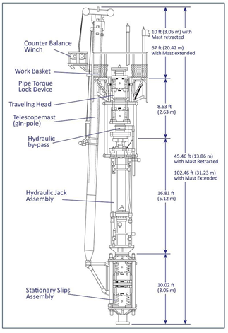
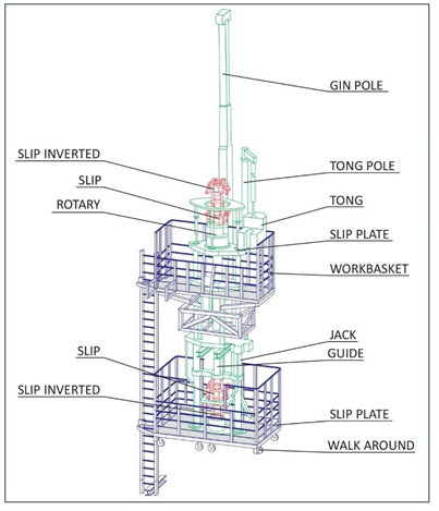
A HWO unit consists of the following equipment groups:
- Hydraulic jack assembly includes the guide tube, window, traveling and stationary slips, rotary table, and power tongs.
- Workbasket, control panel(s), and safety systems.
- Hydraulic power pack, accessories, and hydraulic hoses.
- The circulating system includes a swivel, Kelly hose, tanks, and pumps.
- BOP stack, including control system and hoses.
- Guy wire/support system
Hydraulic Jack Assembly In Snubbing Unit
The hydraulic jack assembly is simply one or more hydraulic cylinders configured to move the pipe into or out of the hole. The snubbing and pulling capacity is a function of the number and size of the hydraulic cylinders and the hydraulic fluid pressure. Many four-leg jacks allow either two or four cylinders to be used for power. When only two cylinders are selected, the load capacity is lower, but the speed is higher. Another method commonly used to increase the jack speed is a regenerative hydraulic circuit.
The regenerative circuit is available only for pulling the pipe out of the hole. By circulating hydraulic fluid from the piston’s snub side to the lift side, the hydraulic volume required for a full stroke is reduced. Although the jack’s lifting capacity is also reduced, the jack speed is increased.
Other important jack components include the guide tube, window and window guide, traveling slips, stationary slips, and rotary table (described below in this section).
Guide Tube
The guide tube is placed in the bore of the jack to provide the lateral support necessary to prevent buckling of the work string. The guide tube is attached below the traveling slips and telescopes up and down with the traveling assembly. This allows a full snub stroke without exposing a laterally unsupported tubular length.
Work Window In Snubbing Unit
The window is located at the base of the jack below the stationary slips; sometimes, the stationary slips are positioned at the base of the window. The primary functions of the window are to provide access for installing large-diameter tools, changing out stripper elements, etc., that will not fit through the jack bore. If the window is open (no lateral pipe constraints), the unsupported length of pipe in the window can fail due to buckling. Therefore, a window guide is placed around the workstring. The window guide constrains the work string in the same manner as the guide tube to prevent major axis buckling of the work string in the window.
Note: Rig assist units typically do not have a work window
Travelling Slips
The traveling slips are located on the assembly, which moves vertically up and down as the cylinder rods are extended and retracted. They grip the pipe to transmit snubbing or lifting force from the jack to the pipe. The jack may be equipped with one or two sets of traveling slips. When two sets are utilized, they are opposed to each other so that one set is used for snubbing (“pipe light”) and the other for pulling (“pipe heavy”).
Stationary Slips In Snubbing Unit
The stationary slips are attached to the base of the jack and are used to hold the pipe while the traveling slips are not engaged. The unit is typically equipped with two sets of stationary slips. One set will be in the heavy position (holding the pipe from moving downwards) and the other in the snub position (holding the pipe from moving upwards). Two sets of stationary snubbing slips are required when there is no visual confirmation of the slip position from the work basket. Using a Closed-circuit TV to monitor the stationary slips is an option.
Two sets of stationary snubbing slips should also be considered when handling large pipe diameters with high wellbore pressures. A general Rule of Thumb is to consider two sets of snub slips when the pipe outside diameter in inches multiplied by the well pressure in psi exceeds 20,000.
Slip Interlock Systems
A slip interlock system is also a requirement for snubbing units. These systems can be divided into two separate components. The first component is a simple mechanical/hydraulic system with indicators that ensure full closure of the opposing slip prior to opening of the load-bearing slip. This system is a significant barrier to prevent pipe release and is commercially available from most snubbing service providers. Shell requires this type of system for both standalone and rig-assist units.
The second component of the interlock system is an electro/mechanical system that provides a positive, measurable, and recordable transfer of load to ensure full load transfer before the opening of the load-bearing slip. This system requires load cells on each slip bowl to accurately measure the full range of load encountered during the operation. Difficulties encountered in the development of this system were as follows:
- Installation of load measuring devices and wiring for each slip bowl is typically not designed or robust enough for oil field conditions.
- Providing load cells that can accurately measure load through the full range of load conditions.
- Difficulty providing accurate load measurements at low load conditions required bypassing some systems at a critical point in the operation (balance point).
Currently, one snubbing service provider in North America has developed a system that fully provides an interlock system with positive, measurable, and recordable load transfer capability. This relatively small company has designed the system for smaller rig-assist type units. Efforts are being undertaken to determine scalability to larger units and provide commercial availability at a global level.
Rotary Table
A snubbing unit may have a rotary table attached to the traveling assembly. The rotary is hydraulically driven and used for milling and fishing operations. Rotary torque is controlled through a hydraulic pressure regulator. When the rotary is in use, a locking device will lock the slips on the pipe.
Rotary speed should be volume-controlled, not pressure-controlled. Pressure-controlled rotaries limit the torque output only, while volume-controlled rotaries control rotary speed and torque output.
Suppose a power swivel is used for pipe rotation. In that case, care should be taken to ensure the passive rotary system is unlocked and the pipe light slip bowl hoses are managed.
Power Tongs
Power tongs will be used in the workbasket to make up connections. The tongs are hydraulic and should be equipped with built-in backup tongs. Built-in backup tongs are essential for pipe handling as other mechanical tongs cannot be used in the workbasket.
Snubbing Unit Workbasket, Control Panels(s) and Safety Systems
The workbasket, located on top of the jack, is used as the crew’s work platform. Controls for the jack, traveling and stationary slips, BOPs, and counterbalance winches are in the workbasket. Typically, there are two main control panels, one for the jack operator and one for the assist operator. The operator controls the jack’s vertical movement and the slips’ operations. A weight indicator displays the snub or lift load of the jack (on most designs, a true
reading is only possible when the jack is in motion). The assist operator operates the counterbalance winches that lift and lower pipe joints to and from the basket. He also controls the two stripper rams, Equalising loop, vent line, and one or two sets of safety rams.
As the workbasket is often a considerable height above the surface, safety systems providing safe access for the crew members are essential. Stairs in different forms are often used as the primary way to and from the workbasket. Fixed stairways should be equipped with adequate fall protection systems, which will guarantee safe climbing conditions for all personnel.
Fixed stairways are not very well suited for emergency conditions, as climbing down them would be too time-consuming. Therefore, the unit must be equipped with an emergency exit system, such as the “safety slide.”
The “safety slide” is connected to the special exit door of the workbasket and provides a fast escape route for personnel in case the workbasket must be evacuated quickly. Two cables suspend the slide from the workbasket, and two dedicated counterweights (8 tons each) hold it in position. The slide can be used by all staff and under all weather conditions. An unconscious crew member may be dropped onto the slide by his crew members without ill effects.
Hydraulic Power Pack and Accessories
The power pack on the ground or deck supplies the hydraulic pressure necessary to operate the jack, partly or entirely the BOPs, rotary, counterbalance winches, lay-down winches, and power tongs. The power pack consists of hydraulic pumps powered by a diesel engine. Hydraulic pressure is controlled through a series of pressure regulators and dump valves. Several different methods are used to control the jack snub pressure. Three hydraulic pressures are commonly referred to; the main system pressure (jack pressure), the BOP operating pressure, and the counterbalance pressure. The purpose of these three hydraulic pressures is described below.
- Main System Pressure (Jack pressure) is the maximum hydraulic pressure available to the jack. The main jack system unloads pressure, which must be set at the required value to snub in the hole. Pressure settings should be such that the jacking force will not exceed the pipe’s calculated buckling load or tensile capacity. Safety factors for both values will be valid and often depend on company regulations.
- The BOP operating pressure is controlled from the basket and supplied to the slips, stripper rams, and safety rams.
- Counterbalance Pressure provides pressure to the counterbalance winches. The required pressure depends on the weight of the joints being used. The assistant operator in the workbasket uses a pressure regulator to control the winches’ lift. NOTE: Do not use more pressure on the counterbalance system than is required to lift the joints to the basket.
Hydraulic Hoses In Snubbing unit
Hydraulic hoses move hydraulic fluid to the jack, BOP’s counterbalance winches, lay-down winches, and the rotary table. Return hoses and transport fluid back to the power pack tanks.
After rigging up, all hoses, fittings, and connections must be tested to the unit’s maximum rated working pressure. The jack’s snub and lift sides must also be tested to the full test pressure. The test can be conducted with the jack in the fully extended and retracted positions, which exerts maximum hydraulic pressure on all lines and fittings in the jack loop.
Circulating System Including Swivel, Kelly Hose, Tanks, and Pumps
The applied circulating system on snubbing units does not differ from those on drilling and/ or workover rigs. A circulating swivel is often used on top of the workstring to pump fluid through the workstring during pipe rotation. As in normal drilling operations, a valve must be placed between the work string and the swivel. In the case of live well operations, the valve placed on the work string should allow wireline plugs to be placed in the work string when needed.
The working pressure of the pumps must be rated for the maximum anticipated surface or circulating pressure.
If nitrogen must be pumped during operations, all equipment exposed to this medium should be approved for this service.
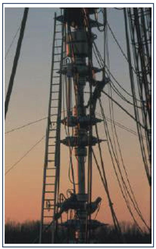
Guy Wire Support System
In almost all cases, the rig up of HWO snubbing units is so high that additional support systems are needed. Static calculations on the entire unit, including all components installed on the unit, such as workbaskets, BOP working platforms, fixed stairs, windbreakers, etc., will dictate guy wire systems for different working heights. These calculations will provide cable dimensions, pre-tension on each wire system, and dedicated dead weights for each rig-up height. As the snubbing units are rigged up on top of the well, additional loads are forced upon the well. If this additional wellhead loading is not allowed, the unit must be supported by a dedicated support structure. The support structure has to provide the guarantee that wellhead loading is prevented.