The well Abandonment process is a necessary operation on oil & gas wells in certain circumstances, such as dry wells and wells, which will be completed later. In this article, we shall explain the standard procedures for doing well plugging and abandonment in oil and gas wells.
Note : This procedures are to be a guide for you as it can be changed according the company policy
Temporary Well Abandonment
Pressure monitoring at the wellhead shall be possible during the temporary abandonment period and before re-entering.
You can abandon the offshore wells at the mudline, with the M.L.S. or Sub Sea Wellhead and proper corrosion caps/location identification devices in place. Pressure monitoring shall be provided by the corrosion cap assembly when wells are ready to be re-entered.
Temporary Well Abandonment Process Procedures During Drilling
The following temporary well plugging & abandonment process procedures during drilling oil & gas wells shall be in mind:
- The well shall be cemented with Drilling kill-weight mud below the plug.
- Where there is an open hole below the last casing (check casing types article), a cement plug ( check our guide for cement plug procedures & calculations article) shall be placed in such a manner that extends at least 50m above and below the casing shoe.
- Locate & verify the top of the cement plug by mechanical loading device.
- If the condition of the formation makes cementing difficult
- Place a bridge plug 50 m above the last casing shoe
- Place +/- 20 m cement plug on top of the mechanical plug.
- Then, set a 50-100 m cement plug into the casing between 20 – 50 m below ground level or the seabed.
Remember that it is better to locate all cement plugs by mechanical loading.
Temporary Well Abandonment Process Procedures During Production
A First Well Abandonment Procedures Case: Production Suspension
Following abandonment procedures shall be considered if it is required to perform temporary well plugging & abandonment processes in producing oil & gas wells for some time.
Note : this temporary abandonment may be for any reason as testing other intervals or suspension of production for a period of time)
- If In the part of borehole where the casing has not been installed and where permeable zones containing liquid or gas have been found.
- Place cement plugs in such a way as to prevent liquid or gas from cross-flowing into other zones.
- Place the cement plug for each zone so that its upper and lower ends are at least 50 m above and below the zone, respectively.
- Locate the top of each cement plug by mechanical loading.
- If the casing is installed and there is an open hole below it.
- Place a cement plug to extend at least 50m above and below the casing shoe.
- If the condition of the formation makes cementing difficult.
- Position a mechanical plug in the lower part of the casing (50m above the shoe)
- Place a +/- 20 m cement plug on the mechanical plug.
These plugs shall be verified by mechanical loading or pressure tested for sufficient time and with enough differential pressure to detect a possible leak.
B Second Case: Temporary Well Abandonment Process Procedures after a production test:
Uninteresting Perforated Zones
- Temporary well abandonment process procedures in these intervals shall use a mechanical plug and squeeze cemented.
- If the formation condition makes cementing difficult, set a 50 m cement plug on top of the mechanical plug.
- If this is not possible, place a cement plug so that the upper and lower ends of the plug are located at least 50 m above and below the perforated zone, respectively, or down to the nearest plug if the distance is less than 50m.
Interesting Perforated Zones
- These intervals shall be isolated utilizing a mechanical plug.
- Then, a cement plug shall be set at least 50 – 100m in length into the casing, depending on casing diameter, between 5 – 50m below the sea bottom.
- The top of the cement plug shall be located and verified by mechanical loading.
Kill String
In some cases, especially when a suspension or temporary well abandonment process is requested, it may be useful for operational and safety reasons to run in the hole a killing string. Running a kill string that is usually made up of tubings, will ensure that when the well is re-entered, pressure control and circulation is possible down to the defined depth.
To be effective, please consider the following:
- A kill string should be run as deep as possible, just above the uppermost plug.
- It will require that a suitable hanger and/or flange featuring a back-pressure control valve is set at the wellhead, allowing for re-establishing circulation and, in case, performing a killing operation while re-entering the well.
Use of kill string rather than setting plugs will be dictated by contingent situations. Use kill string when short-term suspension or when there is temporary abandonment. For long-term suspension/abandonment, or in the case of difficult wells (e.g. sour gas environment, HP-HT, etc.), setting plugs is usually preferred.
Permanent Plugging & Abandonment In Oil & Gas Wells
Why Plugging In Well Abandonment Process
A well has to be plugged so as to effectively seal off all potential hydrocarbon-bearing zones from fresh water-bearing formations and to protect any zones which may contain other minerals.
General Guidelines For How To Plug & Abandon an Uncompleted Oil & Gas Well
- Isolate open hole section.
- Plug all permeable zones to prevent flowing of formation fluid from one zone to another.
- Set the plug(s) so that the top and the bottom is at least 50m above and below the zone(s).
- Test each plug.
- Secure Last Casing Shoe.
- Set the cement plug at least 50m above and below the casing shoe.
- Test the plug shall by mechanical loading.
A Perforated Casing Zones
For Well Abandonment Procedures In perforated Casing Zones
- Squeeze Cement each zone tested through casing perforations as soon as the test is finished, if the well is to be abandoned.
- Set a cement retainer 10-15m above the perforated zone (avoid setting it on a casing collar)
- Perform an injection test using fresh water and record the pressure/flow rate ratios.
- Calculate the cement slurry volume in order to have the cement from bottom perforation to the cement retainer and a minimum of 100 ltrs slurry per metre of perforated zone into the formation.
- At the end of the squeeze, set a 50m cement plug above the cement retainer. (you may reduce the length of this plug to avoid any interference with upper intervals that will be under test or production.)
B Liner
If there were a casing liner (One of Types Of Casing)
- Set a cement plug at the hanging point of the liner,
- The cement plug should cover 50m above and below the hanging point.
- Then perform a pressure test for the cement plug.
- In case small size liner is concerned, set a bridge plug just above the top of liner, then set of a cement plug.
C Other Casings
- In case any of the intermediate casings is not cemented up to at least 100m inside the previous casing shoe,
- Cut the casing at least 100m above the shoe of the previous casing string,
- Recover the casing.
- Then place a cement plug to cover at least 50 – 100m above and below the casing cut point.
- Set a 150 m surface plug 50m or less below ground level or seabed.
- Cut each surface casing and conductor casing at least 5m below sea bed, using mechanical cutters.
General Guidelines For How To Plug & Abandon a completed Oil & Gas Well
The completed wells are divided into on-shore and off-shore wells with or without pressure in the annulus casing/ casing.
In completed onshore wells with pressure in the annulus casing/casing, are foreseen two cases with two phases for each case.
- The Plugging & Abandonment first case is for a well with casings where the top of cement is below the surface.
- The Plugging & Abandonment second case is for a well with casings where the top of cement is at the surface. For such a second case, phase one is as per case I° phase one.
A Plugging & Abandonment First Case
For such a first case, in the first phase, two well zones are analyzed: the open hole zone and the perforated casing zone.
- For Open hole zone,
- If you can retrieve the completion packer:
- Retrieve both the packer and completion string. (This can be done by pulling the unit)
- After, Seal the last casing string above the open hole with a cement plug (by coiled tubing if available)
- The cement plug shall cover at least 50 meters above and below the shoe depth.
- If it is impossible to retrieve the packer:
- Perform cement squeeze in the formation below the packer. Then, cut and retrieve the completion string above the packer.
- If the squeeze is not allowed: in HPHT wells
- Set a bridge plug in the completion string below the packer. (This step is recommended for HPHT wells only.)
- Retrieve the completion string above the packer
- Set a cement plug on the packer.
- If you can retrieve the completion packer:
- For the perforated casing zone each zone tested through casing perforations shall be squeeze-cemented as soon as the test is finished, should the well be plugged & abandoned.
- If you can retrieve the packer, retrieve both the packer and completion string.
- If it is impossible to retrieve the packer, follow the same considerations for the Open hole zone.
- Before setting either cement or mechanical plugs, clear the internal of the casing using a taper mill.
- After, set a cement retainer 10-15m above the perforated zone (avoid setting it on a casing collar)
- Perform an injection test using fresh water and record the pressure/flow rate ratios.
- In the cement slurry, volume calculations will be calculated to have the cement from the bottom perforation to the cement retainer and a minimum of 100 ltrs slurry per meter of the perforated zone into the formation.
- At the end of the squeeze, set a 50m cement plug above the cement retainer. The length of this plug may be reduced to avoid any interference with any upper, perforated intervals to be tested or produced.
- If a mechanical plug is impossible, place a cement plug with upper and lower ends at least 50 m above and below the perforated zone. This solution must be considered as a contingency.
- For both cases, open hole zone and perforated casing zone, the second phase foresees that 20/30 days later, return on the well with a workover rig and verify the previously performed hydraulic seal of the plugging.
Retrieve all casing as much as possible and cut at least 100 m above the shoe of the previous casing string, subsequently, place a cement plug in such a way to cover the casing at least 50 m above and below the casing cut point.
B Plugging & Abandonment Second Case
The second case is for a well with casings where the top of the cement is at the surface. For such a second case, phase one is as per case I phase one.
Phase two, for such a second case, foresees that.
- If there is a cement between the annulus casing/casing, to insulate the pressures,
- Make a window in zones suitable to allow the positioning of the inflatable packer.
- Place a 50 m-long cement plug above the inflatable bridge plug.
- In completed onshore wells without pressure in the annulus casing/casing, when the cement top is above the shoe of the previous casing, the utilization of the drilling rig unit can be avoided and the well abandonment operations procedures will be carried out utilizing the best technique available considering both economic and operative constraints.
- If the top of cement is under the shoe of the previous casing, it will be mandatory to carry out a cement plug 100 m long in the annulus casing/casing by circulating through the casing perforations.
- Perform the cement plug test by pressurizing the top of the plug with a 1500 psi differential pressure.
- Several levels with the same hydraulic regime (homogeneous formations, pressure and production fluid) can be plugged by means of two cement plugs, provided the lower extends at least 50 m below the bottom of the deeper level and the upper extends at least 50 m above the top of the higher level.
- Place a fluid with the same characteristics as that one used during the running of the production casing between such two plugs
- If SBHP is lower than the hydrostatic pressure of the production fluid, cement all annuli to the surface, and the completion string will be totally abandoned in the well.
- In the other situations, recover the completion string up to 50 m under the shoe of the surface casing or in any case not deeper than 250 m from the surface.
C Offshore Wells specification
The use of a workover rig is mandatory. For explorative and completed offshore wells, the well abandonment process will be carried out following the procedure (above-specified) for onshore wells, making a distinction between the two cases (pressure or not in the annulus), but performing the operation in one unique phase.
What Is The Main Cement Plugging Procedure
- Set Cement plugs in place using an appropriate tail of pipes:
- Hole sizes < than 12 1/4”: a length of tailpipe exceeding the planned height of cement plug made up of 27/8” tubing should be used.
- Hole sizes > than 12 1/4”: tail pipe made up of used drill pipes up to 5” may be used as an alternative for tubing.
- Deep – high-temperature plugs: It is suggested that the tail pipe is made up of fiberglass tubing (27/8” – 31/2”, depending on availability and hole size); the length of tailpipe should exceed the plug height.
- Cement plugs height should be not less than 100 m and not more than 200 m; plugs height less than 100 m may be justified when set in combination with mechanical plugs or when in large diameter holes.
- In some conditions and depending on requirements and programs, materials other than cement (e.g. resins or compounds, gravel, sand, carbonate, etc.) may be considered.
- Use neat slurries whenever possible for cement plugs while abandoning wells. If static bottom hole temperature exceeds 110°C use special non-degradable cements (i.e. Geotherm).
- Fluids featuring the same maximum density requested while drilling shall be left in the hole performing the abandonment operations.
- If there are different pressure gradient regimes in the formation, consider setting cement plugs in order to limit the differential pressure gradient for contiguous formations to 0.2 kg/cm2/10 m or less.
- Pump spacers ahead and behind slurry.
- Special consideration should be given to the composition and volume of the spacers when the mud is oil-based mud, calcium chloride, or lignosulphonate treated.
- The hydrostatic head reduction due to the spacer volume and density should be calculated. The spacers should have a volume corresponding to a length of at least 328ft (100m).
- Calculate the slurry volume using a caliper log, if available. When a caliper log is unavailable, use a slurry volume excess based on local experience. Set plugs exceeding 200m in length in one stage.
- If there is a washout in the hole or you are expecting potential losses, setting two short plugs instead of one long one is preferable.
- As a rule of thumb, spacing between plugs over 1000 m should be avoided in cased holes.
- Place all cement plugs using a tubing stinger.
- Calculation of Displacement is necessary to spot a balanced cement plug (hydrostatic heads inside the string and outside in the annulus shall be the same).
- An under displacement of 1 or 2 bbl will help drain the slurry of the pipe when pulling out of the hole.
- After setting the plug, pull out slowly 30 – 50m above the theoretical top of the plug and direct circulate (consider reverse circulation if conditions allow it).
- Monitor and record spacer and slurry returns.
- Never stab the cement stinger back into the plug to avoid plugging of the stinger.
- Using a drilling or workover rig, the position and efficiency of all cement plugs shall be verified by locating the top of the plug and by applying bit weight on the plug after cement setting, usually 20,000-40,000lbs, but dependent on hole size).
- Keep a record of all plugs set and the results of tests shall be available for inspection.
Casing Cutting/Retrieving
Consider that, most likely, performing these operations will be with a work-over rig, so pay attention to issues such as work-over rig capabilities and safety issues.
Consideration can be given, if deemed economically profitable, to cut and retrieve sections of uncemented 7″ and 95/8″ casing.
- Use Mechanical cutters for this operation.
- Check annulus pressure prior to carrying out casing cutting operations. Pay attention in order to equalize fluid weight inside and outside the casing prior to carrying out casing cutting operations.
Annulus pressure shall be bled off and subsequent pressure build-up monitored; depending upon build-up behavior, the following options may apply:
Fast pressure build-up:
- Punch holes are punched in the casing some 100 m above the recorded T.O.C.
- Circulate well with Heavy mud weight, capable of withstanding the annulus pressure through holes to control annulus pressure.
- As an alternative, you can circulate/squeeze cement (depending upon actual conditions) through holes for the same scope.
Slow or no pressure build-up:
- Cut casing carefully some 100-200 m above the recorded T.O.C.
- After cutting the casing, perform a complete circulation to reduce friction and balance the mud.
- If you have finished cutting and recovering the casing, leaving a stub, you can use one of the following methods to plug the casing stub.
Stub Termination (Inside A Casing string)
A stub inside a casing string shall be plugged by:
- Set a cement plug so as to extend 50m above and 50m below the stub,
- Set a permanent bridge plug 10-15m above the stub and then cap it with at least 20m of cement.
Stub Termination (Below A Casing String)
If the stub is below the next larger string, plugging shall be accomplished in accordance with the previous section.
- A mechanical test of the plug is necessary.
- After setting a surface plug, each surface casing and conductor pipe shall be cut at least 5m below sea bed/ground level using mechanical cutters.
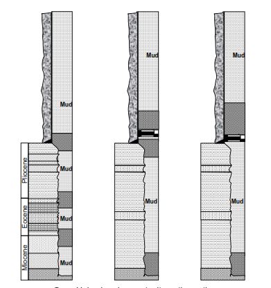
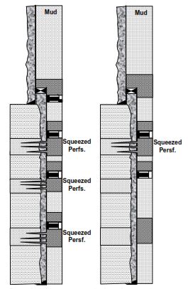
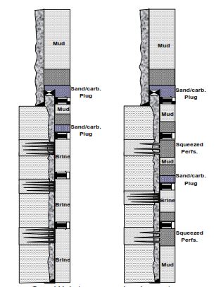
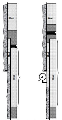
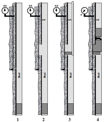
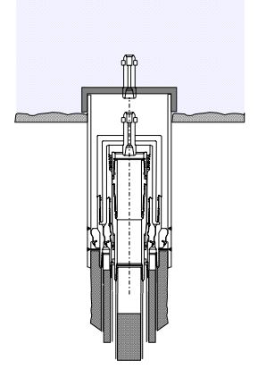
Well Plugging & Abandonment Procedures Sketches
The following sketches have the sole scope of illustrating concepts and criteria expressed in this procedure.
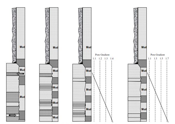
procedures alternative options
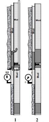
Un-cemented annulus pressure
cemented annulus pressure
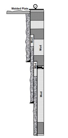
surface (land)
mudline (off-shore)
Ref:
Eni S.p.A. Exploration & Production division | Drilling Completion & Production Optimization | Well Operating Standards