After successfully perforating using wireline guns, experts proposed that they could run similar guns on pipes. This allowed for longer sections of the gun to be utilized, reducing the rig time required for well completion. Further time savings could be achieved by combining the guns with the completion string. In the 1930s, Halliburton patented the idea of running perforating guns on tubing. But it only gained widespread use since the late 1970s. The acceptance of Tubing Conveyed Perforating (TCP) guns has increased due to an improved understanding of their effect on good productivity and advancements in equipment reliability and safety.

What Does TCP Mean In Oil and Gas Industry?
A perforation is simply a conduit between the reservoir and the wellbore. A perforation is a flow path for the oil and gas (in the reservoir rock) to be able to move to the surface. TCP guns or Tubing Conveyed Perforating means transporting or conveying a perforating gun into a well via tubing, drill pipe, or coiled tubing. There are also TCP gun systems that are conveyed into the well via slickline or wireline. TCP methods can provide advantages over other perforating methods as there are no limits on the overall length of the guns or the well deviation. This can save time on many wells.
Remember that the gun can fire through mechanical, electrical, hydraulic, or combined methods. Once you place the TCP guns in the well, you cannot remove them until you retrieve the completion. In addition, they may stay in the well until a workover is required. Misfires pose a significantly higher risk than wireline guns. This is because you must remove the completion or drill string from the well to re-run the gun. Therefore, ensuring the reliability of the equipment used for tubing conveyed perforating is crucial.
Application Of Tubing Conveyed Perforating

- Underbalance Situations: TCP guns (Tubing Conveyed Perforating) allows perforations with high wellbore underbalanced pressures. You can perform perforating under any desired conditions of underbalance. Furthermore, you can immediately produce the well to clean up the perforations.
- Horizontal Wells: We can push TCP guns along the hole to the desired perforating depth. Therefore, it is easy to perforate highly deviated or horizontal wells where conventional wireline techniques are not feasible.
- Save time: Tubing-conveyed guns are highly versatile, and we can use them with various tubular strings, including drill pipe, production tubing, or coiled tubing. To maximize their benefits, running the guns as part of a completion string will avoid additional trips. This also enables the assembly and testing of the Christmas tree and production equipment before perforating.
TCP Gun Design
TCP guns are similar in design to wireline semi-expendable hollow carrier guns (Fig. 2), with many components in common.
- They are available in a range of sizes from 54 mm (2 1/8″) to 184 mm (7 1/4″) outside diameter. We generally can run an unlimited length of guns; thus, perforate intervals up to 1000 m have been reported.
- The maximum gun assembly diameter that can be used is limited only by the inside diameter of the production casing. The increase in gun diameter compared with through-tubing guns permits the use of more powerful charges at higher shot densities, improving inflow performance.
- The limited clearance between the gun and the casing pipe permits the optimal positioning of the guns in the borehole, allowing the shots to be phased through 360° without the reduced penetration performance associated with large stand-offs.
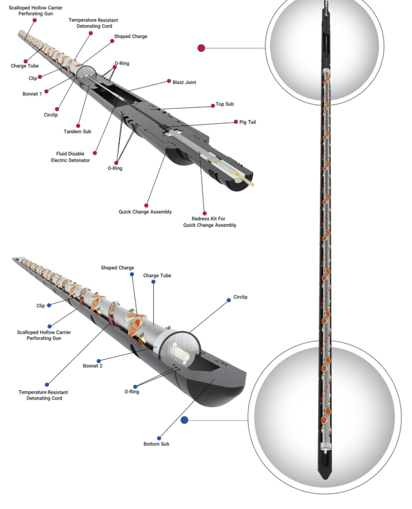
Source: Perfnix
TCP String Configuration
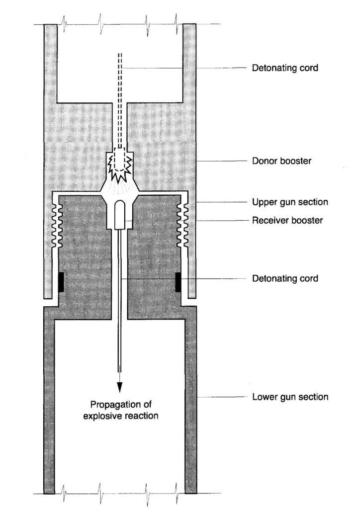
TCP guns are made up vertically in the well by assembling preloaded guns and blank sections to give the required perforation intervals. The gun sections should contain only secondary explosives and can be safely transported and stored until required. A strand of detonating cord runs the length of each gun or blank section and must align with the strand in the adjacent section to allow the detonation train to pass from one section to the next.
Booster
A booster is used at either the end of each gun or blank section to maintain high-order detonation during the transfer. Boosters should contain only secondary explosives. The use of boosters containing lead azide or other primary explosives should be discouraged as these will cause the gun to detonate if exposed to excessive heat or shock Fig. 3. The transfer system is shown schematically in Fig. 34.
Safety Joint
At the top of the gun, a blank section, referred to as the safety joint, is used to ensure that the loaded gun sections are at a safe depth below the rig floor before the firing head is attached.
Tubing Conveyed Perforating Firing Head
The firing head contains the detonator, which will be used to fire the guns when they have been correctly positioned in the well. When the firing head has been attached, the gun is armed and must be treated with extreme caution.
Perforated Joint & Release Sub
Above the firing head, a perforated joint and release-sub are normally fitted. The perforated joint allows well fluid to flow into the tubing after perforating. The release (or drop-off) sub, which may be actuated by wireline or by the shock of the gun detonation, is used to drop the guns into the sump of the well after firing.

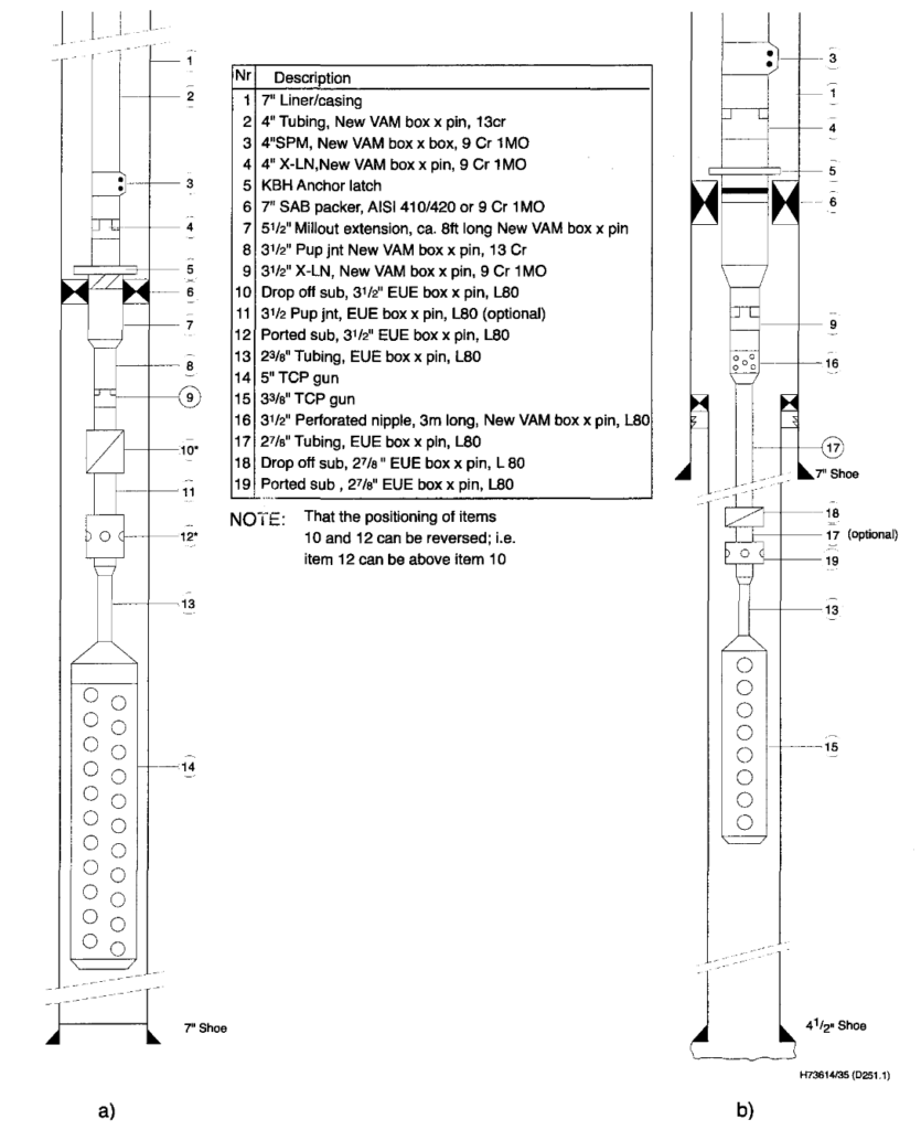
Tubing Conveyed Perforating (TCP) & Completion String
Above the release sub, the completion design will be essentially the same as would be used when perforating with wireline. The wells packer and gun can be run as part of the completion and set with the tubing, or it may be set before the completion is run. The packer may then be set on a drill pipe or wireline with the guns suspended, as shown in Fig. 5 . If a wireline is used, the maximum length of the gun will be limited by the strength of the cable. Alternatively, the packer may be set before running the completion, and the guns and tailpipe stung through the packer, as shown in Fig. 5 . The maximum diameter of guns that can be used in this case will be determined by the bore of the packer.
Packers
Suppose running the packer with the completion. In that case, it will be essential to determine the depth of the packer relative to open hole logs before setting it. This is to determine the intervals to perforate. Normally, we can achieve that by running a combination of GR and CCL through the tubing. This combination will correlate the packer depth with the open-hole gamma-ray log. In addition, we could place weak radioactive marker sources in a connection of the casing liner or production casing and the completion to facilitate correlation, particularly if the open hole gamma ray log lacks character. If the packer is set before running the completion, and the gun is then stung through the packer on the completion, the packer depth can be used to locate the guns at the correct depth for firing.
Once we position the guns correctly, we can suspend the completion. Then, we can install the Christmas tree and flowline to prepare for the well production.
Underbalanced Perforation
To establish the required underbalance, one can reduce the hydrostatic pressure of the wellbore before firing the guns. The mechanical strength of the casing and completion components limits the underbalance. If there was a perforation in the well before the TCP run, one can install a surge disc or production valve below the packer and run the tubing partially empty. Immediately before firing the detonator, the drop bar ruptures the disc or opens the valve, causing a flow surge into the tubing and instantly drawing down the wellbore pressure while firing the guns.
Tubing Conveyed Perforating (TCP) Firing Systems
Experts have developed various detonator firing mechanisms to ensure the reliable firing of TCP guns in wells with differing geometry, mechanical configuration, and borehole conditions. These methods fall into four main types, designed to enable the effective firing of guns.
- Drop bar actuated systems, in which a metal bar is dropped from the surface and free falls under gravity to mechanically initiate the firing head;
- Hydraulically fired systems, in which we apply a fluid pressure from the surface to the tubing or annulus to fire the gun;
- Electrically actuated systems: this system works by sending a current from the surface via an electrical cable to fire the gun;
- Electrically actuated systems, in which we lower a detonator and shaped charge from the surface of the wireline to fire the gun.
The operation of mechanically or electrically actuated systems depends on well geometry and mechanical restrictions in the completion. In contrast, using hydraulically fired systems requires a detailed analysis of other completion items’ operating pressures or pressure ratings.

Although Fig. 7 indicates the use of lead azide. Note: lead azide boosters are almost obsolete within the industry due to their intrinsic sensitivity to thermal and shock loading.
Drop Bar Systems In Tubing Conveyed Perforating
Drop bar systems are suitable for wells with deviations of up to 65°. In dry tubing, one can control the speed of descent by running the bar on slickline or by using a fluid cushion to decrease the velocity through tubing accessories and the packer. However, any scale or debris in the well may prevent the drop bar from initiating the firing head. If the guns fail to fire, it is mandatory to fish the bar using slickline, which reduces the risk of unintentional firing if a misfire occurs. Then, we shall recover the gun. The estimation of the overall reliability of drop systems is more than 99%.
Hydraulically Fired Systems
In a hydraulically fired system, the firing pin is actuated by a piston driven by hydraulic pressure. The piston is mechanically restrained while the gun is run into the hole, and is released to fire the gun. The piston may be released by applying excess pressure from surface to the tubing or annulus or by using a drop bar. Hydraulically actuated systems can be used in highly deviated wells, and can be less susceptible to problems caused by scale or debris than electrical or mechanical systems. The estimation of the overall system reliability is greater than 95%.
When designing a hydraulically fired system, it is important to consider the presence of the string of setting tools, pressure-actuated valves, or shear disks. To operate each equipment item sequentially while allowing for operating pressure tolerances, we must also consider the burst and collapse pressures of the tubing and casing. Additionally, it is necessary to calculate the differential pressure range between the annulus and tubing to which the assembly will be subject while running in the hole or creating drawdown. This is to prevent the unintentional firing of the gun. Pressure differentials created by a failure to maintain the fluid level in the tubing while running in may be sufficient to actuate the firing head.
Electrically Fired Systems For Tubing Conveyed Perforating
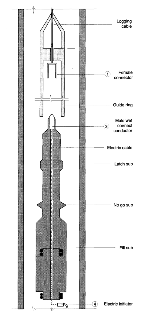
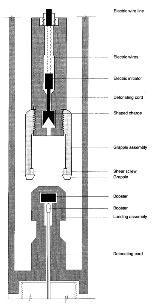
Electrically fired systems are similar to those used in wireline guns. Fitting a wet connector above the gun, will allow making an electrical connection with a wireline cable run through the completion Fig. 8 . The current sent down the cable actuates the detonator initiating the gun. Alternatively, a shaped charge may be run through the completion on the wireline and fired into a booster to trigger the gun Fig. 37 . In addition, running production logging sensors on the wireline cable will allow monitoring of pressure, temperature, and flow while firing the gun. Limited information on the reliability of electrical firing systems for TCP applications is available.
Shot Indicators
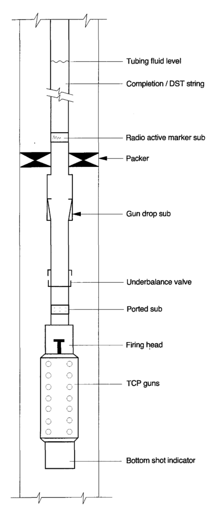
After firing the guns, there is no way of knowing whether all charges in the string have fired correctly until the guns are removed from the hole. Service companies offering TCP have developed tools that trigger a delayed second detonation when the detonation reaches the bottom of the gun string “Bottom Shot Indicator”), but low-order detonation of sections of the gun may remain undetected. Figure 10 illustrates a “bottom shot indicator”. The detonation can generally be monitored from the surface using a microphone attached to the wellhead. In some cases, particularly in deep wells or with high ambient noise levels, indications of firing at the surface are inconclusive. If the well fails to produce as expected, we could attempt a re-perforation with wireline guns. This will require dropping the Tubing Conveyed Perforating TCP guns from the completion string into the well.

Y Block Applications
A Y block cross-over tool is a connector used in TCP assemblies to allow perforation guns or other tools to be side-mounted relative to the main completion string. These tools are commonly used for the following reasons:
- Selectively shooting and producing two zones through one tubing string.
- Hanging off submersible pumps (ESP). This allows the installation of a pump and gun in one trip.
- Saving time and perforation charges (blank guns costs) to perforate two widely spaced zones.
- Perforating horizontal wells under balance whilst maintaining through tubing access to the well’s horizontal section.
Hydrostatically actuated firing heads are generally used for Y tool applications, requiring the use of time delay firing heads to achieve under balance if run in a single completion. In a dual completion type like that in Fig. 11, we can fire the gun by creating a pressure differential between the long and short strings. The differential pressure firing head is set to initiate when the required drawdown is reached in the short string; fluid is then removed from the short string until the gun fires. The “Y” block contains a non-return valve preventing flow from the perforations to the long string. Readers should contact the major perforating service companies for more Y block details.

Auto Release Gun Hangers
The recent development of the Auto Release Gun Hangers (ARGH) enables the application of all the benefits of Tubing Conveyed Perforating TCP techniques to monobore completion techniques. ARGHs are available from several service companies. Before or after installation and testing of the permanent completion, ARGHs allow positioning the perforating assembly opposite the zone of interest using a suitable work string (either drill pipe or tubing). In addition, it allows for the support of slip assembly. The workstring is then retrieved. When the guns have fired, small, shaped charges release the slips, allowing the perforating assembly to fall to the bottom.
The main advantages of this system are that:
- Perforating long and/or deviated intervals without sacrificing gun performance.
- Maintaining full bore access across the completion interval.
The main disadvantage of this system is that there will be a need for a long sump to drop the guns.
Shoot & Pull
After firing the guns, it is mandatory to kill the well if there is a need to recover the TCP guns. Therefore, they are either left hanging below the packer or dropped into the rathole, where they remain while the well is produced. In certain circumstances, it may be necessary to kill the well and remove the guns to allow wireline or coiled tubing access to the perforated interval if, for example, there is insufficient rat hole into which to drop the guns.
This is known as the “Shoot and Pull” technique. A disadvantage of the “Shoot and Pull” technique is the likelihood of formation and perforation damage occurring when the well is killed. The most serious disadvantage of tubing conveyed perforators is that in the event of a misfire, the completion must be pulled from the hole and re-run to replace the guns, the alternative being to drop the guns and perforate with through tubing wireline guns. TCP techniques have contributed to a larger number of unintentional firing incidents than those involving wireline-conveyed guns, both at the surface and downhole.