A straddle packer can isolate a selected part of a completion while preserving a route through the well. Whether that is a useful repair depends on the exact connection being excluded, the places where the assembly can seal and the passage left afterward. Covering a leak is only one part of the decision. The repaired completion must still provide the production and servicing functions that the well needs. [1, pp. 499–501, 544] [3, pp. 872–875]
This article follows a local repair from the defect to the remaining flow path. It distinguishes a retained packoff from a temporary treatment arrangement and explains why neither a tool name nor a successful placement establishes every isolation claim. The drawings are functional concepts, without vendor settings, rated limits or an installation program.
What Does a Straddle Packer Isolate?
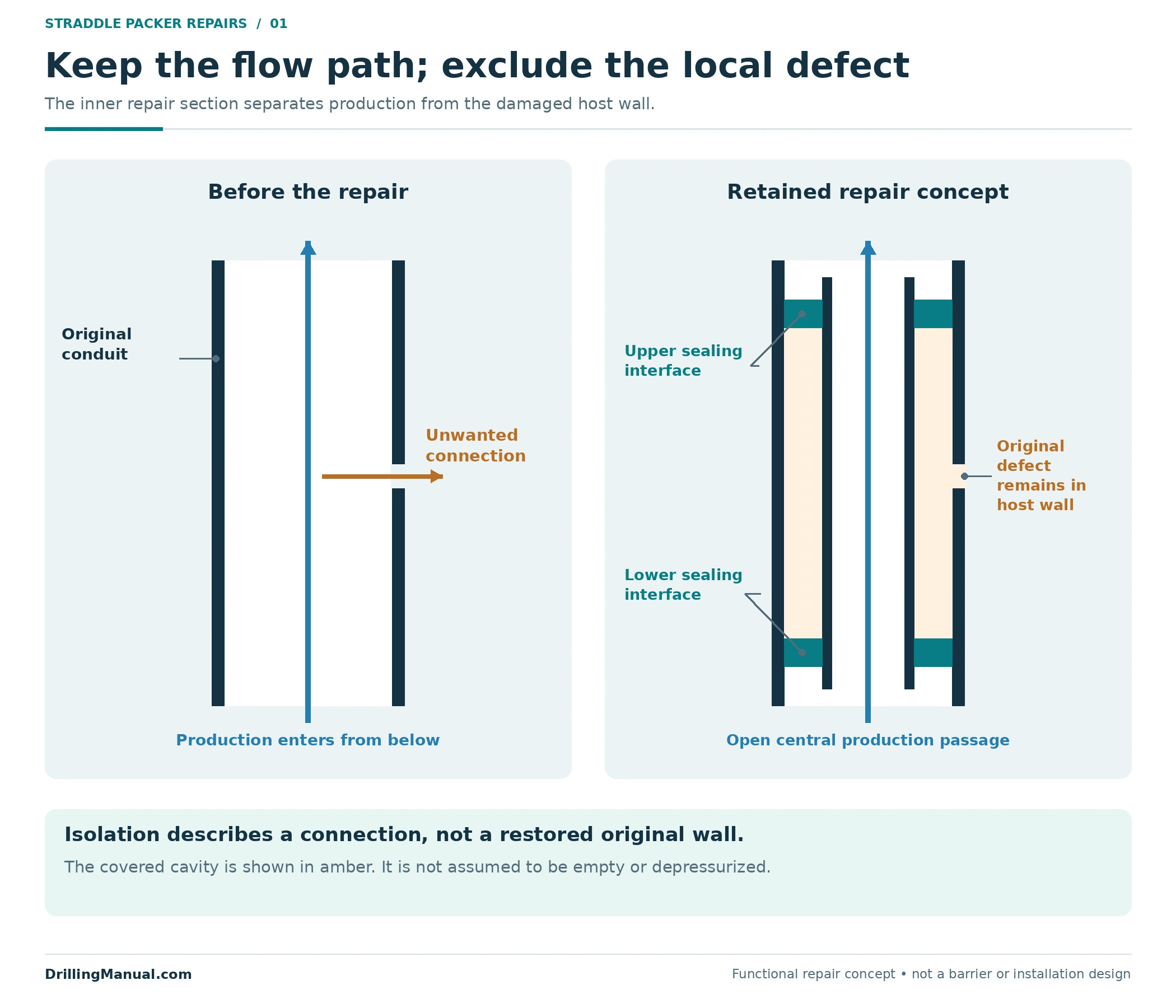
A straddle packer spans an interval between separated sealing boundaries. In the repair concept illustrated here, a sealed inner section covers a damaged part of the original conduit. Its upper and lower interfaces prevent production inside that inner section from communicating with the covered defect. The central passage remains open so fluid from below can continue upward. This describes the intended topology, not a particular commercial assembly. [1, p. 544]
The book gives a useful completion-specific example: prepared profiles around a blast joint allow a straddle packoff to be placed across that joint if it fails. The provision exists because suitable interfaces were included in the original completion. It is not evidence that any damaged length of tubing automatically offers suitable locations to anchor and seal a repair. [1, pp. 499–500, 544]
Trace the proposed flow path in three parts: production entering below the repair, flow inside the repair section, and its connection to the conduit above. Then trace the unwanted connection separately. A drawing that colors the damaged section as “isolated” without showing those connections leaves the important question unanswered: isolated from which fluid path?

A Straddle Packer Can Serve Different Jobs
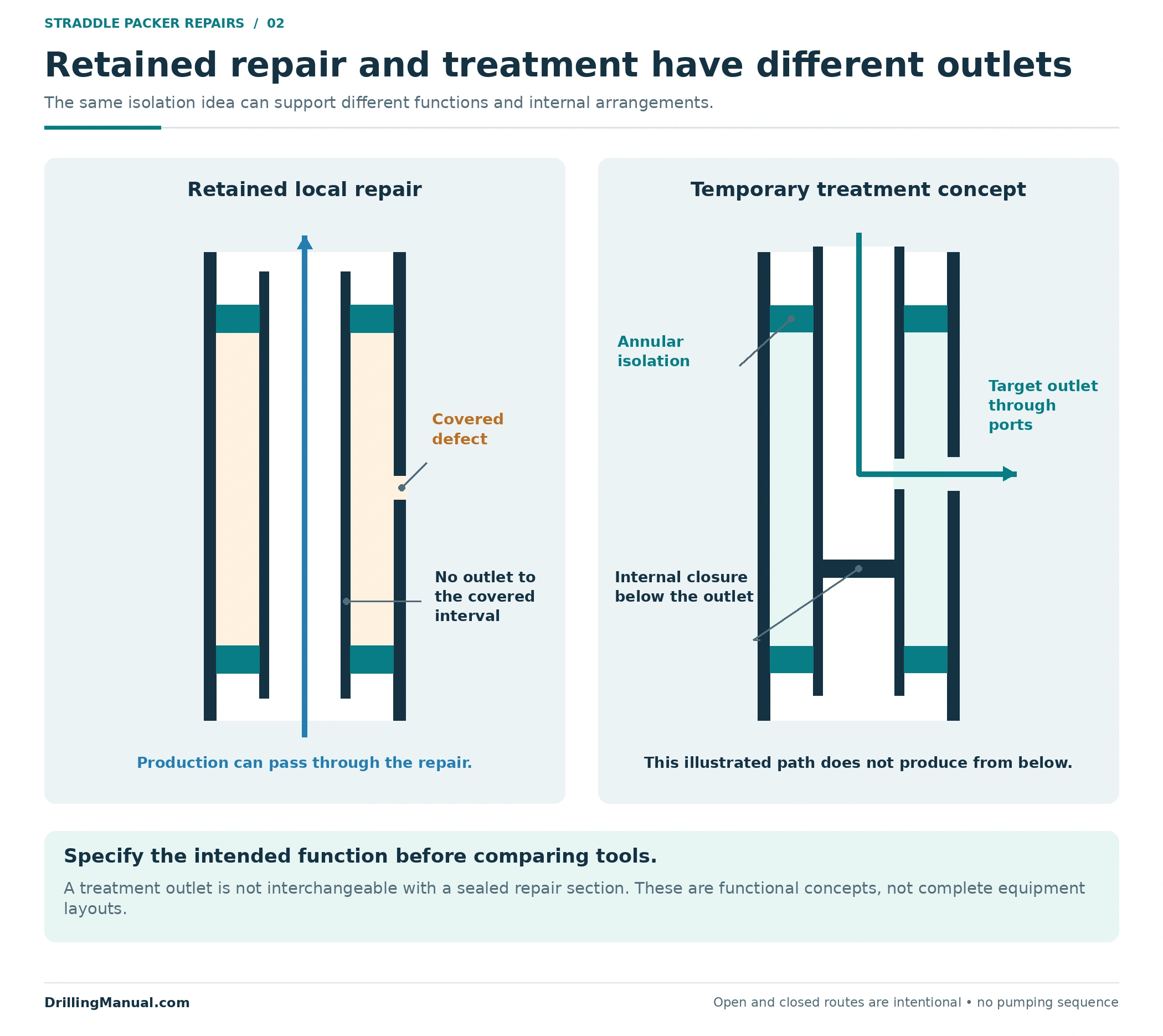
The same broad term appears in repair and treatment discussions, but the required flow arrangement changes with the objective. A retained repair section is intended to exclude a local leak while leaving the specified production route available. A treatment arrangement instead gives access to a selected interval between isolating elements. The book identifies straddle packers among the tools used to isolate a target for chemical placement. [1, p. 544] [2, pp. 845, 858]
| Objective | Connection required | What must not be assumed |
|---|---|---|
| Cover a local tubing or device leak. | A contained passage past the defect, with appropriate sealing interfaces at both ends. | That the original damaged component has regained its original condition. |
| Place treatment in a selected interval. | A delivery route into the bounded interval, with the intended neighboring paths isolated. | That the placement assembly will remain as a production repair. |
| Exclude an unwanted producing connection. | Closure of that connection while preserving any production required from elsewhere. | That a wellbore closure removes every reservoir or external communication path. |
Figure 2 therefore shows two different concepts. The repair has an open through-bore and no outlet into the covered section. The treatment concept has a deliberate outlet into the isolated target and a lower internal closure that directs the illustrated delivery. That closure belongs to the stated treatment concept; it would block the deeper production route if mistakenly transferred into an open-bore repair drawing.
The duration also belongs in the description. The intervention handout describes a packoff across a leaking sliding side door as a temporary solution, using the device’s nipple profile and polished bore. That example does not establish a universal service life for every straddle packer. The intended period, later access and eventual recovery must be stated for the selected design. [4, p. 102] [3, p. 875]
Locate Both Straddle Packer Sealing Interfaces
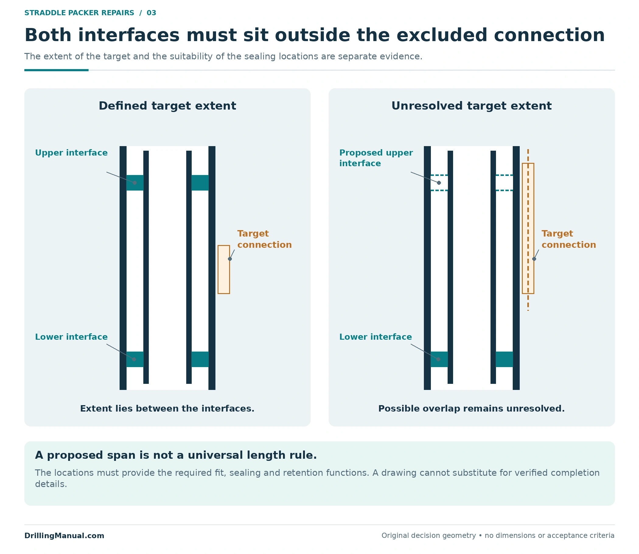
A repair proposal needs more than a single suspected leak depth. It needs the extent to be covered and the intended upper and lower interfaces. In the book’s profile-based example, the completion provides the locating, locking and sealing provisions. Its landing-nipple discussion explains why the lock must match the specified profile: location, mechanical engagement and sealing are related but distinct functions. [1, pp. 499–501, 544]
Apply that distinction to the proposed assembly. Identify where it will be located, what provides its retention and which surfaces form each seal. A generic pair of dark bands on a schematic cannot establish those functions. If the straddle packer uses a different anchoring or sealing method, the actual equipment design must supply the corresponding information.
Also check the relationship between the defect and the seals. The intended covered interval must lie within the isolation boundaries. If part of the unwanted connection lies above the upper boundary or below the lower one, the drawing does not demonstrate its exclusion. This is an original geometric check, not a prescribed distance beyond a leak or a rule for choosing seal spacing.
For example, imagine two otherwise similar proposals. Proposal A places both interfaces in identified compatible locations outside the entire target. Proposal B shows only the leak center and chooses its length before establishing the interfaces. A may be ready for the remaining engineering checks; B is incomplete even if its nominal length appears generous. Neither proposal can be accepted from a length label alone.
Compare the Original Bore With the Remaining Bore
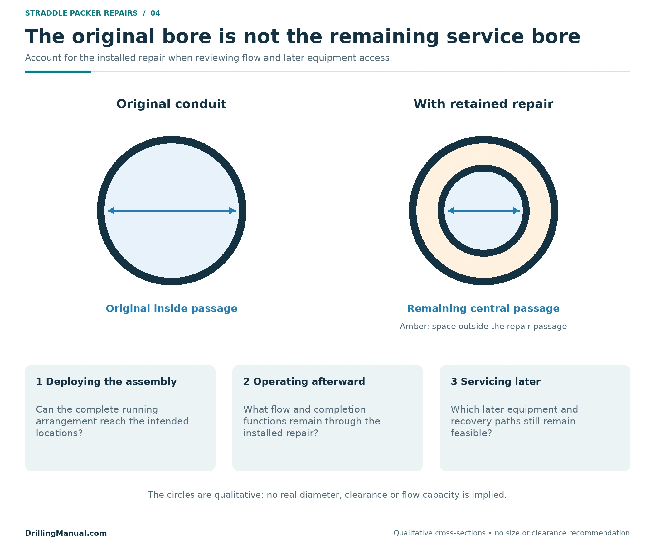
A straddle packer installed inside an existing conduit introduces another internal geometry. The relevant passage is the complete post-installation route, including local profiles and other restrictions. The book’s no-go-nipple discussion makes this point directly: the smallest restriction controls which equipment can pass, and repeated reductions can compromise production or servicing. [1, pp. 500–501]
Separate three dimensions in the review: the space available to deploy the assembly, the bore left after installation and the dimensions of equipment that may later need to reach below it. A deployment check is not a future-access check. A tool can fit through the original tubing while the installed repair creates a smaller route for the next intervention.
Figure 4 deliberately uses no real tubing size. It compares an original passage with an inner repair section and shows the remaining open bore. Its purpose is to make the change visible. Actual dimensional acceptance also depends on the selected assembly, local restrictions and the intended servicing function; the picture is not a clearance specification. [1, pp. 500–501] [3, pp. 872–875]
The production consequence also needs evaluation. An open hole through the repair proves a route exists in the drawing, but it does not prove that the route delivers the required performance. The source links small profile restrictions with both production and service limitations. Retaining continuity and retaining acceptable capacity are separate questions. [1, p. 501]

A Straddle Packer Does Not Resolve Every External Path
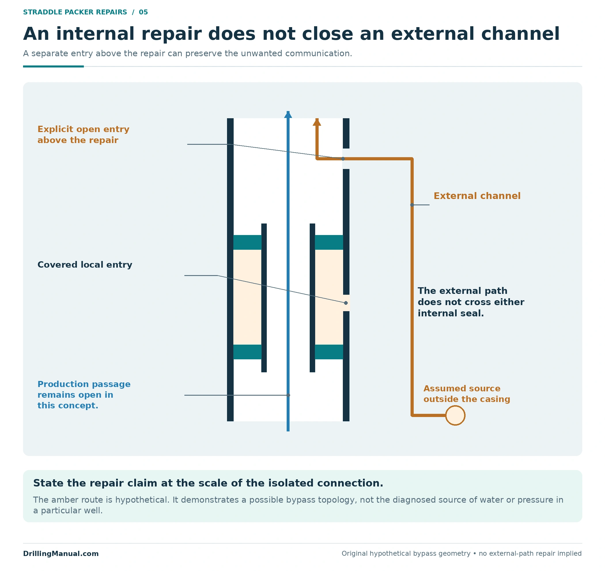
Local isolation inside a conduit does not automatically establish isolation outside that conduit. The book’s discussion of selective recompletion explicitly retains a requirement for properly cemented casing and liners. The separation created by internal tools and the separation provided outside casing are different parts of the completion. [3, p. 895]
Consider the original schematic in Figure 5. The internal assembly covers one entry interval. A hypothetical external channel still connects a source below it to another open entry above the upper seal. That route never crosses either internal sealing interface. The figure does not diagnose such a channel; it shows why the claimed repair boundary must be compared with the proposed unwanted path.
This distinction also matters when the objective is water control. The book warns that a target may be incompletely isolated or contain interleaved layers that cannot readily be separated. Mechanical access to an interval does not mean the reservoir will honor the same boundary. Selection and placement therefore depend on where the treatment must act and what neighboring inflow must be protected. [2, pp. 858–859]
The separate water-shutoff guide examines source diagnosis and treatment selection. Here, keep the question narrower: does the proposed local isolation actually interrupt the unwanted connection identified for this repair? If the answer depends on an unverified external seal, record that dependency.
Define the Straddle Packer Service Conditions
The selected arrangement must be assessed as part of the completion. The book treats fluid environment, component compatibility, service requirements and the intended life as interacting design decisions. Adding a repair section does not remove those interactions. It changes the configuration to which they apply. [3, pp. 872–875]
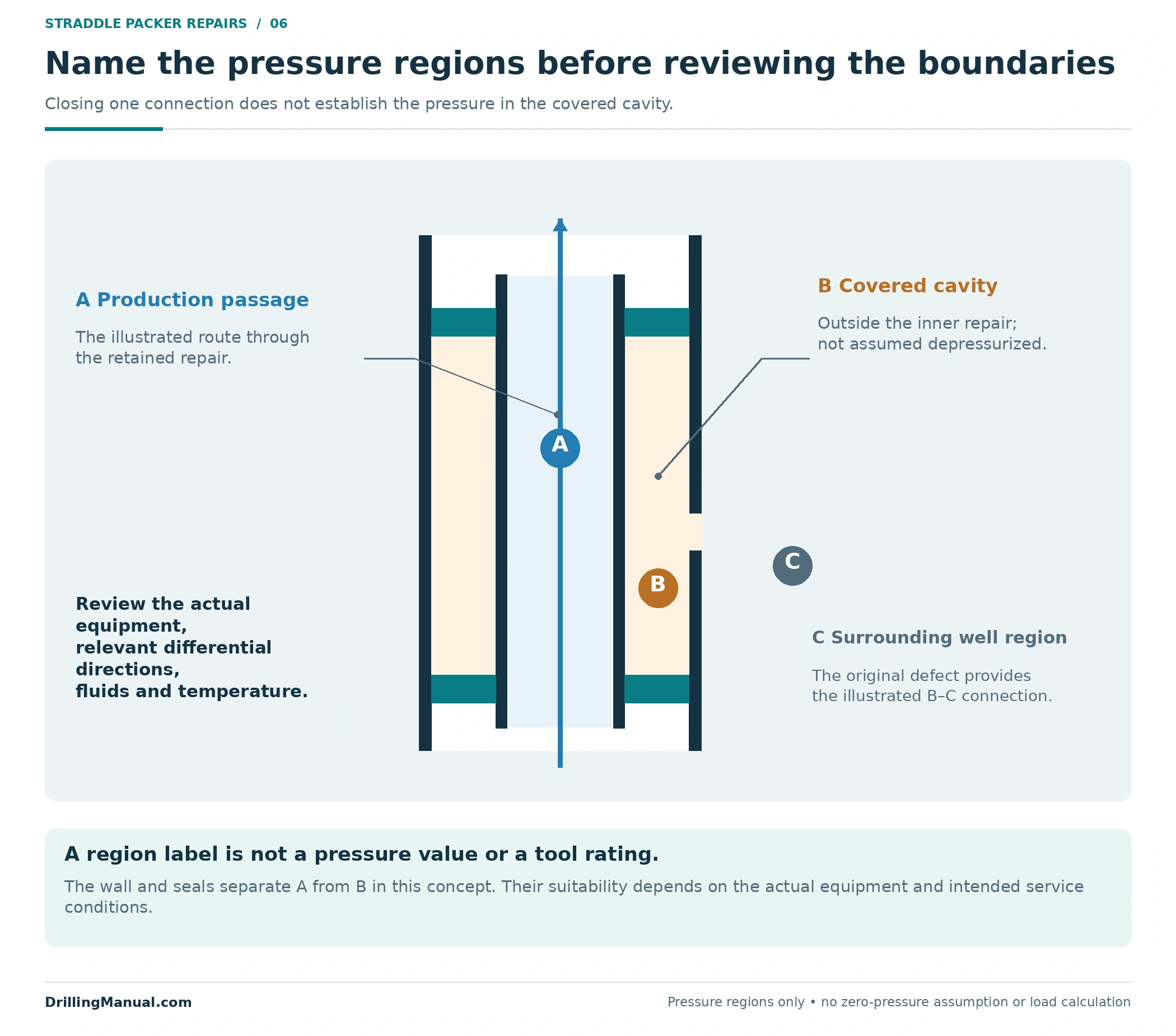
For a straddle packer, the review should identify the pressure regions on each side of the proposed boundaries, the differential directions relevant to the intended service and the fluid and temperature conditions. These are questions for the actual equipment documentation and well design. No pressure or temperature value in a generic illustration can substitute for that assessment.
Likewise, do not assume that a stated capability applies equally to every direction, fluid or operating state. Record what the selected assembly is expected to do during its intended service and which later changes would require reassessment. This is an editorial application of the book’s functional-design approach, not a new tool rating. [3, pp. 872–875]
Figure 6 labels the production passage, the covered cavity and the surrounding well region separately. Those labels help reviewers ask which boundaries are being loaded. The covered cavity is not drawn as an empty or depressurized space: excluding its connection to the central production passage does not establish its pressure.
Build a Repair Comparison That Includes Later Access
A useful comparison follows the whole proposed change. The table below is an original review framework based on the source’s profile, access and completion-design principles. It is intended to expose missing information before a local repair is described as an adequate alternative to more extensive workover operations. [1, pp. 499–501, 544] [3, pp. 872–875, 895]
| Decision question | Evidence to retain | Unresolved condition |
|---|---|---|
| What connection is being excluded? | Defect extent, source/path interpretation and the intended isolation boundaries. | Only a pressure symptom or leak center has been identified. |
| Where can the assembly function? | Locating, retention and sealing interfaces appropriate to the selected design. | Nominal tubing size substitutes for interface information. |
| What remains open? | The production route and the complete remaining service-access route. | An open central passage is treated as proof of all required capacity and access. |
| What happens later? | Intended service conditions, monitoring objective and recovery or subsequent-intervention provisions. | The proposal ends at installation and omits its effect on the next job. |
A local repair may avoid recovering the full tubing string in a completion designed to permit that approach. The book’s monobore example illustrates the value of planning access and selectivity into the completion. It does not establish that every straddle installation is rigless or that every damaged completion remains suitable for through-tubing repair. [3, p. 895]
The packer-types overview and packer selection guide provide broader hardware context. This decision is specifically about a bounded repair and its remaining functions. If coiled tubing is considered as a conveyance or service option, the coiled-tubing guide supplies that separate equipment context.
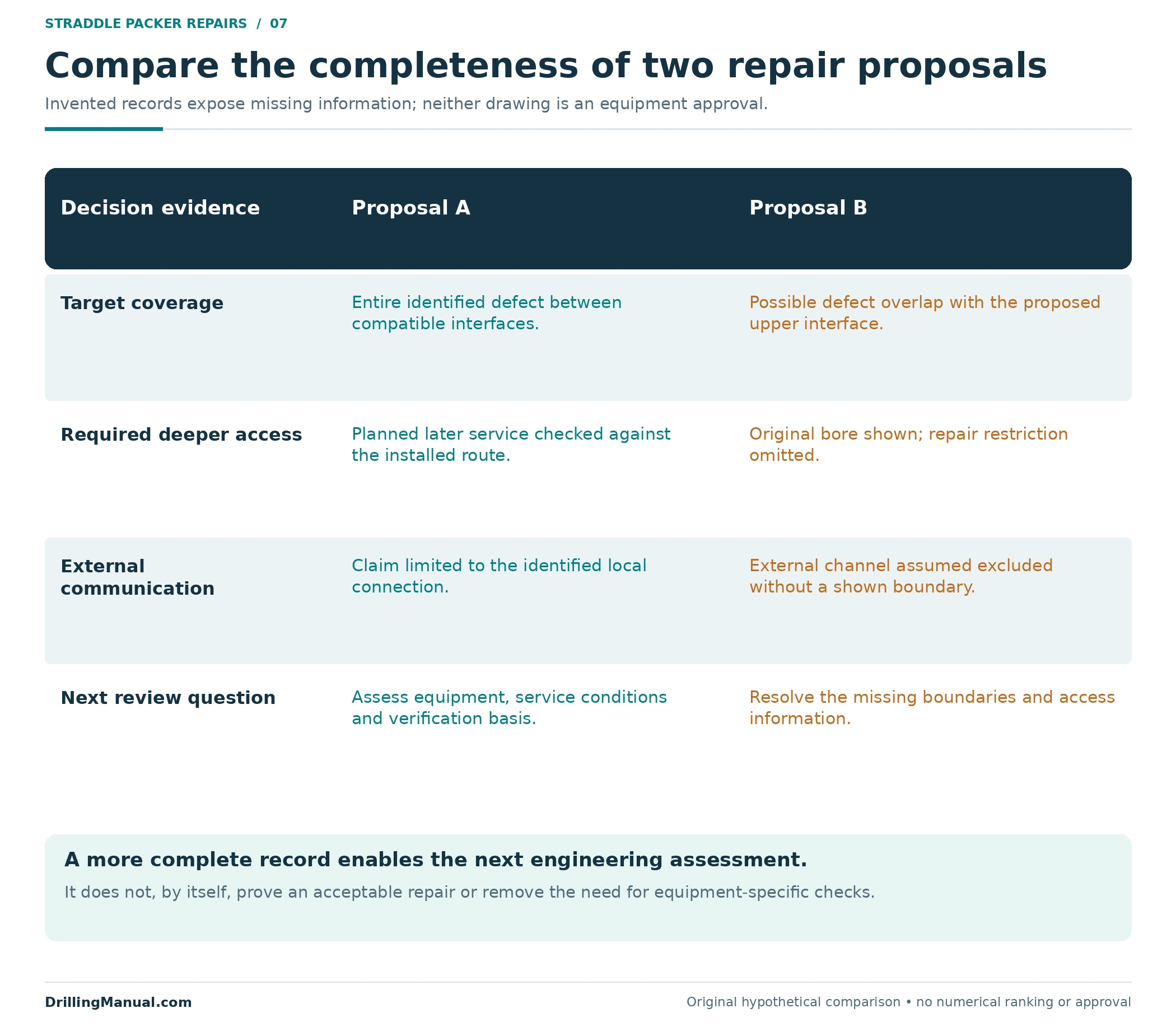
The following two hypothetical records show how that comparison can change the decision without changing the apparent leak location. They are invented review cases, with no tool dimensions or claimed field outcome. The difference is the evidence surrounding the target and the function required after repair.
| Original hypothetical record | Proposal A | Proposal B |
|---|---|---|
| Target coverage | The entire identified defect lies between two documented compatible interfaces. | The suspected defect extends into the proposed upper interface; its full extent is unresolved. |
| Required deeper access | The planned future service is checked against the complete post-installation route. | The proposal shows the original tubing bore but omits the installed repair restriction. |
| External communication | The claimed isolation is limited to the identified local tubing connection. | The proposed benefit also assumes an external channel is excluded, without showing how. |
| Review conclusion | Proceed to assess the actual equipment, service conditions and verification basis. | Resolve the missing boundary and access information before treating the concept as an adequate repair. |
Proposal A is not approved simply because its drawing is more complete. It has identified the questions that can now be assessed against the selected equipment and well. Proposal B illustrates why “the tool spans the leak” is too weak a description: the endpoint may be unsuitable, the later service route may be restricted and the expected benefit may depend on another path entirely.
A straddle packer comparison should preserve those unresolved items rather than merge them into a single statement that the repair is feasible. Clear limits help a reviewer distinguish missing information from a known restriction. They also prevent the installed geometry from being mistaken for evidence that every required function has already been verified.
Verify the Function Being Claimed
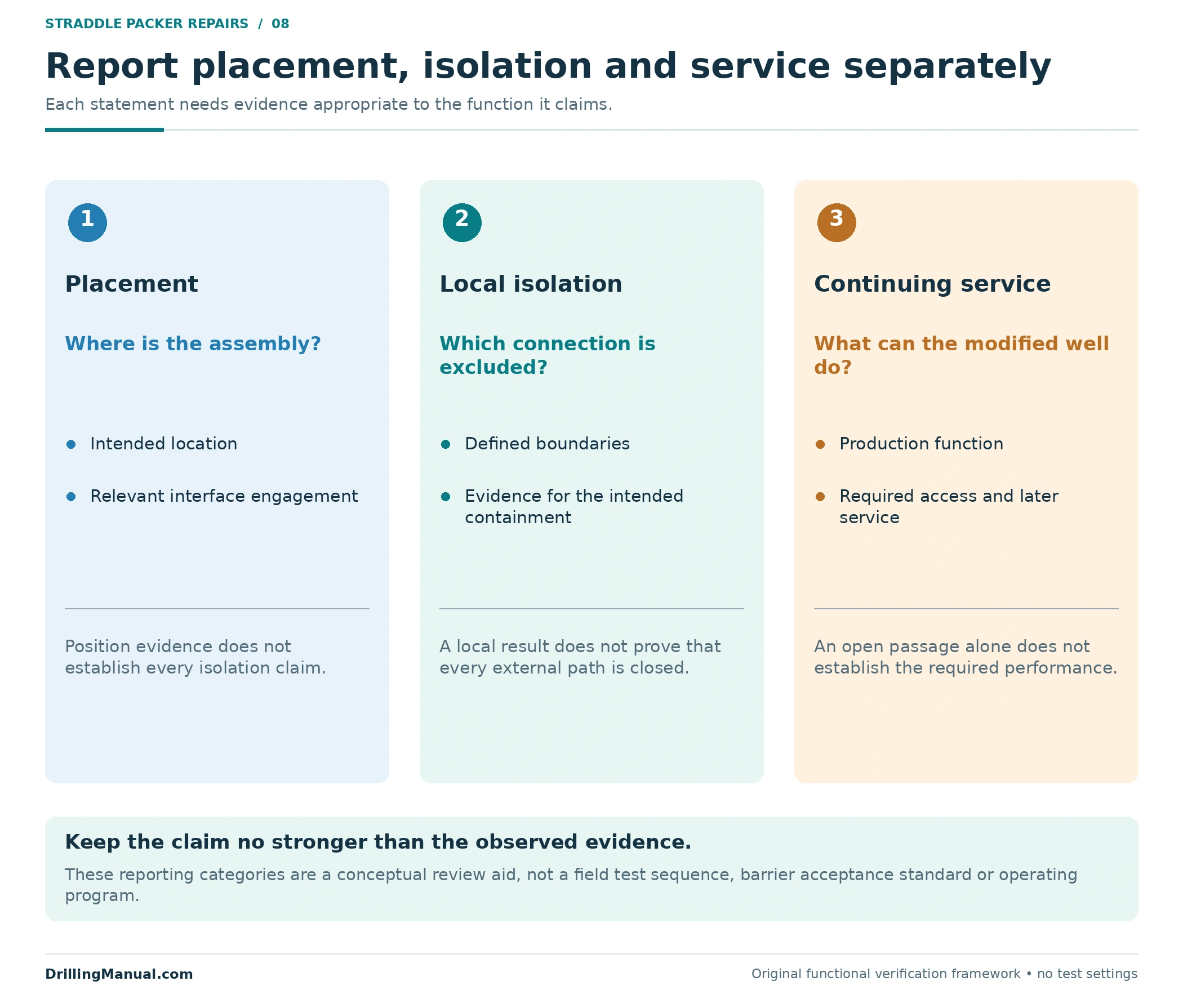
Keep placement, local isolation and continuing performance as separate statements. Evidence that an assembly reached its intended location addresses position. Evidence appropriate to the intended pressure boundary addresses local containment. The subsequent production and access record addresses what the modified completion can do. These review questions do not prescribe a test sequence or acceptance standard.
A straddle packer result should therefore identify the tested or observed configuration and the limits of the conclusion. A local finding does not establish external cement isolation, exclude every other leak or show that the original tubing has been restored to its former condition. Similarly, an initial production response does not document all future intervention access.
The handover should preserve the installed geometry, the covered interval, the remaining bore and the intended service period. Those details make later decisions possible when conditions or objectives change. They apply the book’s central design principle: the completion has to satisfy explicit functions over its planned life, with the interactions between components understood. [3, pp. 872–875]

Common Questions About Local Repairs
Is a straddle packer the same as a production packer?
The term here describes local isolation across a selected interval. The completion examples distinguish a straddle packoff from the production packers and other devices already present. Describe the assembly’s function and interfaces rather than treating the names as interchangeable. [1, p. 544]
Can production continue through the repaired interval?
It can in an appropriate open-bore repair configuration, as illustrated here. A different internal closure or treatment arrangement may not preserve that route. Check the actual final geometry and its required production and servicing functions. [1, pp. 501, 544]
Is every retained packoff a permanent repair?
No service duration follows from the name alone. The handout’s sliding-side-door packoff is described as temporary, while the completion-design chapter requires an intended service life to be considered. State the selected arrangement’s purpose and duration explicitly. [4, p. 102] [3, p. 875]
Will the same intervention tools still pass?
That must be checked against the remaining route. Local restrictions can determine the equipment that reaches below them, and an installed inner repair changes that route. Original tubing ID alone is insufficient. [1, pp. 500–501]
Will a straddle packer stop a behind-casing channel?
Not merely by isolating an internal interval. If an external route reaches another open entry beyond the seals, it can bypass that internal boundary. The source explicitly retains properly cemented casing and liners as a requirement for selective completion behavior. [3, p. 895]
What pressure rating should be used?
The selected equipment and well design must establish it for the intended conditions and direction. This article provides no universal rating, setting pressure, release load or acceptance test. Its purpose is to make the isolation and access questions clear before those specific engineering decisions are made.
Book References
- Dunn-Norman, Shari, Charlie Williams, Morris Baldridge and Wade Meaders. “Completion Hardware,” Chapter 11 in Petroleum Well Construction, edited by Michael J. Economides, Larry Watters and Shari Dunn-Norman. John Wiley & Sons, Halliburton educational version. Visible/physical PDF pp. 499–501 and 544 in the 903-page copy.
- Hardy, Mary, and Thomas Lockhart. “Water Control,” Chapter 17 in Petroleum Well Construction, visible/physical PDF pp. 845 and 858–859. Used for selective placement and isolation limitations, without reproducing treatment procedures.
- Dunn-Norman, Shari, and Clark Robison. “Designing Well Completions for the Life of the Field,” Chapter 18 in Petroleum Well Construction, visible/physical PDF pp. 872–875 and 895. Historical field-specific dimensions, settings and operating examples are not adopted.
- Well Intervention Pressure Control training handout, descriptive title from the supplied filename 659344307-04-Handout-Well-Intervention-Pressure-Control.pdf, p. 102 of the 208-page copy. Printed and physical PDF page numbers agree. Author, publication date and edition are not established in its inspected front matter. Used only for the sliding-side-door packoff example.