Water shutoff in oil wells aims to reduce unwanted water production by interrupting the responsible flow path or changing how water moves through the treated interval. Choosing a plug, cement treatment or chemical system comes after identifying that path. The decision must also account for oil that may be lost when an interval is isolated or its permeability is reduced. [1, 2]
A high surface water cut describes the produced mixture. It does not establish which interval supplied the water, how it reached the well, or whether that interval still contributes useful oil. This guide connects those questions to treatment selection, placement and evaluation. Its drawings and numerical example are original educational constructions.
Define the Water Problem and the Intended Benefit
Some water production accompanies useful oil production. The water-control chapter in Petroleum Well Construction evaluates excessive water against oil production, water-handling costs, equipment capacity and reservoir conditions. A universal water-cut percentage cannot make that decision for every well. [1]
Water may consume lifting, separation, transport or disposal capacity. Its presence can also affect the well’s flowing conditions and contribute to corrosion, scale or sand-related problems under the relevant fluid and formation conditions. Reducing water can therefore have value, but the proposal must identify the actual constraint it is expected to relieve. [1]

Photo: Bob Wick / BLM, via Wikimedia Commons, Public domain (U.S. government work). Resized and converted from JPEG to WebP; no crop or content alteration.

Distinguish downhole water shutoff from surface produced-water treatment. The first changes a subsurface production path or its flow response; the second handles water after production. Improving a surface facility does not identify a downhole water-entry point. The broader workover operations guide places water control among intervention objectives. [1]
Separate the Water Source, Entry Point and Connecting Path
Ask three questions before selecting a treatment: Where does the water originate? Where does it enter the wellbore? What connects those two locations? A water-bearing interval may feed its own perforations, or water may travel behind casing and enter through another interval. Reservoir communication can also deliver water through a productive interval that continues to supply oil. [1, 2, 3]
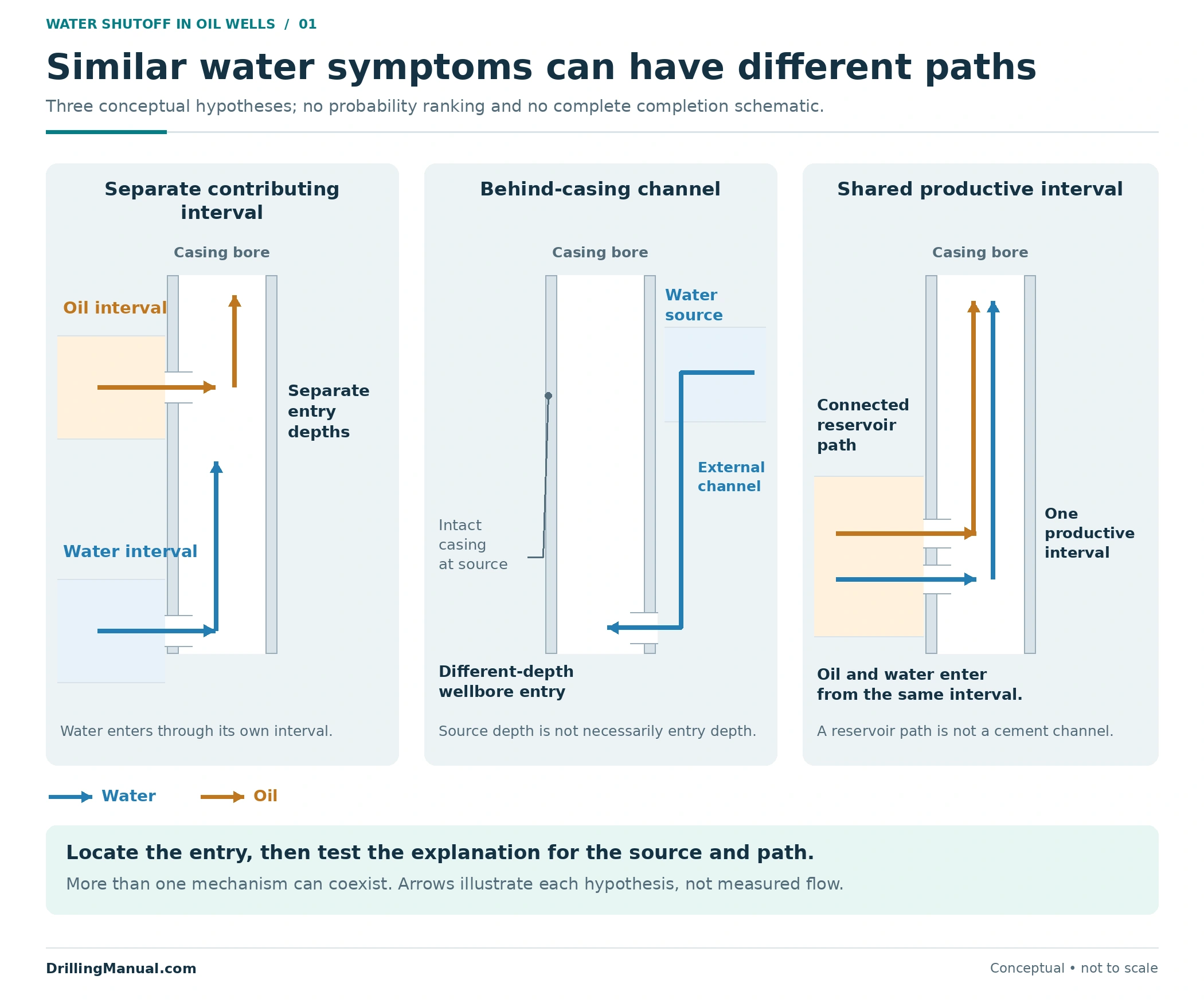
| Candidate situation | What the evidence must establish | Why the distinction changes the treatment |
|---|---|---|
| A separate water-contributing interval | Its oil and water contributions, access and communication with adjacent intervals | Selective isolation may be appropriate, but any oil from the excluded interval is also at risk |
| A channel behind casing or another completion-related path | The complete route from the source to the observed entry, including possible alternative entries | Closing one wellbore opening may leave the external route connected to another opening |
| Reservoir water entering a productive interval | How water and oil share the interval, including layering, fractures and relevant reservoir communication | A treatment that blocks the interval or reduces its permeability can impair useful oil inflow |
These are starting hypotheses, not an exhaustive list or a ranking of likelihood. The book also describes completion into water, casing leaks, high-permeability communication, fractures and stimulation-related water entry. More than one route may require investigation. An abrupt water increase provides timing evidence; it does not uniquely identify one mechanism. [1]
Completion geometry changes the interpretation. A multiple-zone completion may provide boundaries and connections that an open-hole completion does not. Establish the actual arrangement before transferring a cased-hole isolation concept to another well. Detailed coning calculations are outside this article’s treatment-selection scope. [1, 2]
Build Evidence That Answers the Treatment Question
Begin with the completion history, oil and water rates, operating changes, stimulation history and available reservoir information. Relate the onset of water to those records, then identify the unknown that could change the treatment choice. Petroleum Well Construction specifically treats the cost of additional diagnosis against the risk of treating the wrong mechanism. [1]
A useful investigation distinguishes interval contribution from source identification. A production survey may identify a water entry without proving that the water originated in the rock immediately behind that entry. Schlumberger’s cased-hole reference illustrates the value of combining flow, fluid-property and temperature information when fluid moves behind casing. [3]
| Evidence | Useful question | Interpretation limit |
|---|---|---|
| Oil/water history and operating records | When did the behavior change, and what changed at the same time? | Similar surface trends can accompany different water-production mechanisms |
| Production logging with fluid-property measurements | Which intervals contribute fluid, and how can the phases be allocated? | Multiphase slip, deviation, sensor response and fluid conditions affect the interpretation |
| Temperature and suitable supporting flow/noise evidence | Where is there evidence of fluid movement, including possible movement behind casing? | A localized response does not independently identify the full source-to-entry path |
| Cement evaluation and completion records | What supports or challenges a proposed external communication path? | Cement evaluation and active-flow localization answer different questions; interpret them together |
Do not substitute a local water holdup for a produced water-rate fraction. In multiphase flow, phases can move at different velocities. The cased-hole reference also requires the relevant fluid properties and conversion between downhole and surface conditions. Keep the measurement basis explicit when comparing a downhole allocation with surface production. [3]
The cement bond log guide provides background on cement evaluation. For a suspected channel, the decision still needs evidence for the proposed fluid route and the access required to treat it. A cement-quality observation alone should not be converted into a complete water-source diagnosis. [1, 3]
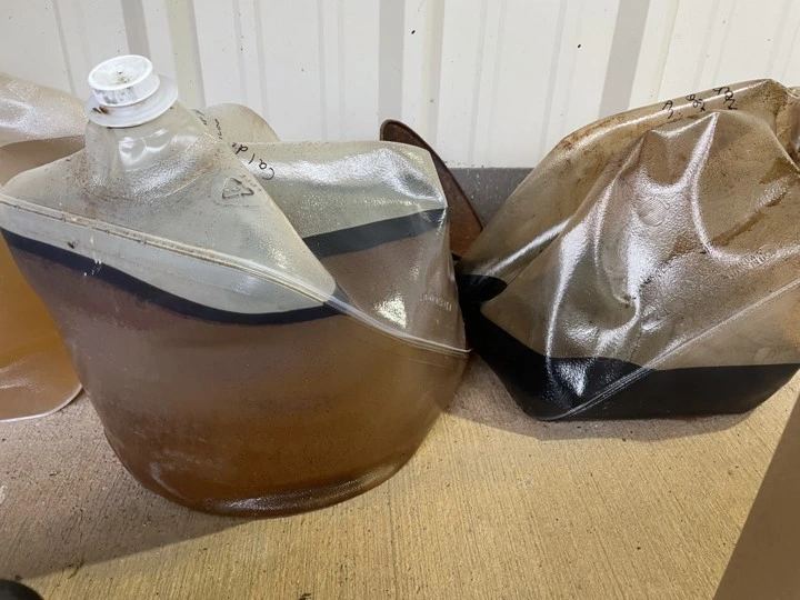
Photo: Bonnie McDevitt / USGS, Public domain. Converted from JPEG to WebP; original dimensions and framing retained.
Choose the Intended Flow Effect Before Choosing the Material
“Mechanical or chemical?” is only part of the selection. The more useful first distinction is between stopping all production from a target, reducing its permeability, and reducing water permeability more than oil permeability. The book treats these as different objectives. A material name alone does not establish which effect a particular formulation and placement will deliver. [1]
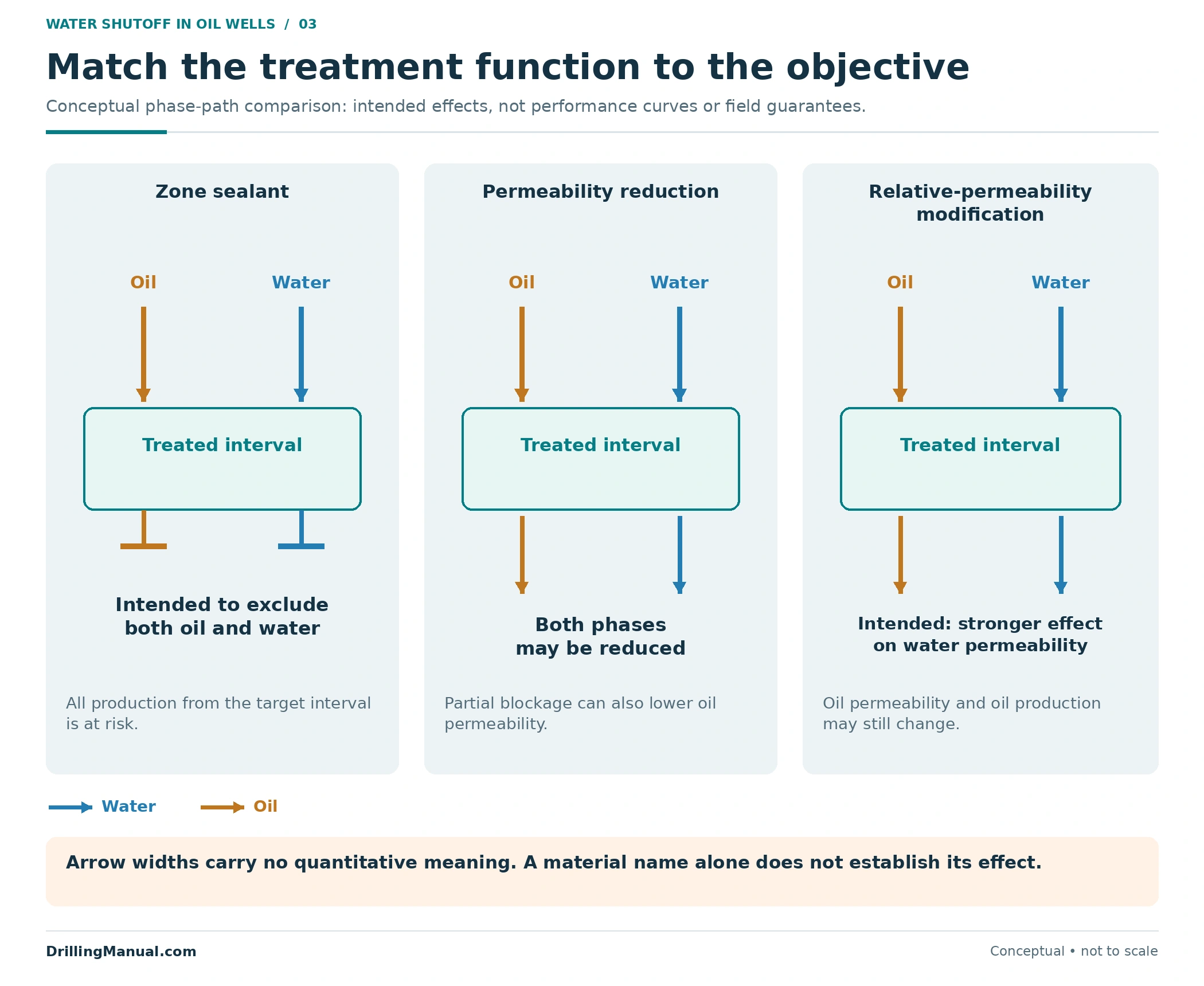
| Treatment objective | Possible approach | Main selection question | Oil-production consequence to assess |
|---|---|---|---|
| Close a defined wellbore interval or connection | A suitable mechanical isolation device or installed completion control | Does the closure intercept the complete unwanted path, with acceptable remaining access? | All production excluded by that boundary, including oil, must be accounted for |
| Seal the target flow channels | A suitable wellbore or matrix zone sealant | Can the material reach and seal the intended channels under the relevant conditions? | A complete zone seal intentionally stops both oil and water from that target |
| Reduce permeability without completely sealing the target | A permeability-reducing treatment | Will the reduction and its placement meet the objective? | Ordinary permeability reduction can impair oil as well as water |
| Reduce water permeability more than oil permeability | A suitably qualified relative permeability modifier | Is the preferential effect supported for the rock, fluids and treatment conditions? | Preferential reduction does not guarantee unchanged oil flow or permanent effectiveness |
Mechanical isolation, cement and gels are therefore not interchangeable answers to “high water cut.” The same broad chemical family can be formulated or placed for different effects. Likewise, placing a material in the wellbore and placing it within the rock matrix impose different coverage and performance requirements. [1]
A behind-casing repair may involve a sealing treatment, but the water-shutoff decision must first establish its target and expected effect. The separate squeeze cementing guide addresses that operation’s background. This article supplies the source-and-treatment decision framework rather than a pumping program. [1]
When Does Mechanical Isolation Match the Water Path?
A bridge plug can exclude a lower completed interval, while an appropriately configured sliding sleeve can close a selected completion connection. The installed geometry determines what is isolated and what remains connected. The water-control chapter emphasizes mechanical isolation where there is little opportunity for the water to reach another open section of the well. [1]
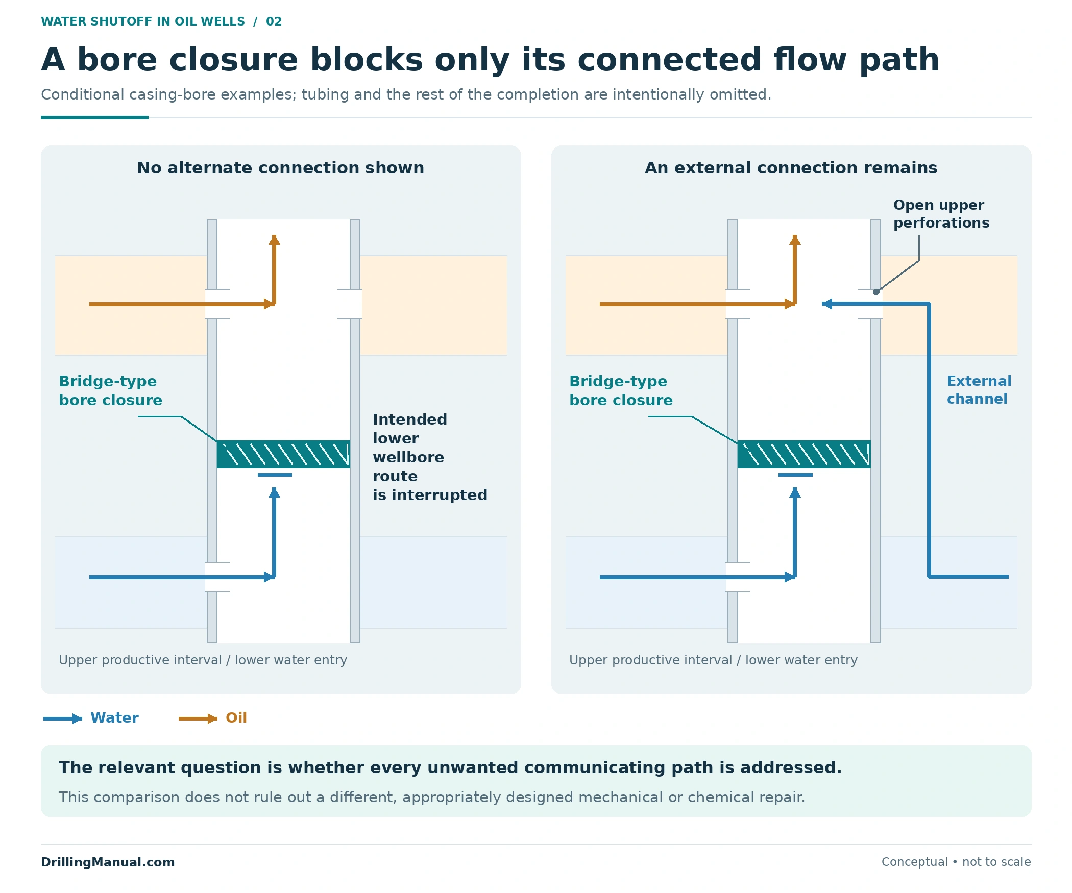
The illustration compares two different path conditions around a similar wellbore closure. In the first, the unwanted lower inflow is excluded. In the second, a channel outside casing still connects the water source to open perforations above the closure. The closure may perform its intended local function while the water problem remains. [1, 2]
That example does not mean a mechanical solution can never address a completion-related problem. It means the selected boundary must match the supported path. Review the relevant packer and completion interfaces, bypass possibilities, remaining producing intervals and future access before defining the isolation objective. [1, 2]
Placement Must Reach the Target and Protect Useful Inflow
A technically suitable material can still be misplaced. The book distinguishes injection without mechanical zone isolation from placement using a defined isolation arrangement. With several intervals open, a proposed injection route does not by itself prove that the treatment will remain in the intended interval. Relative injectivity, formulation and the actual completion matter. [1]
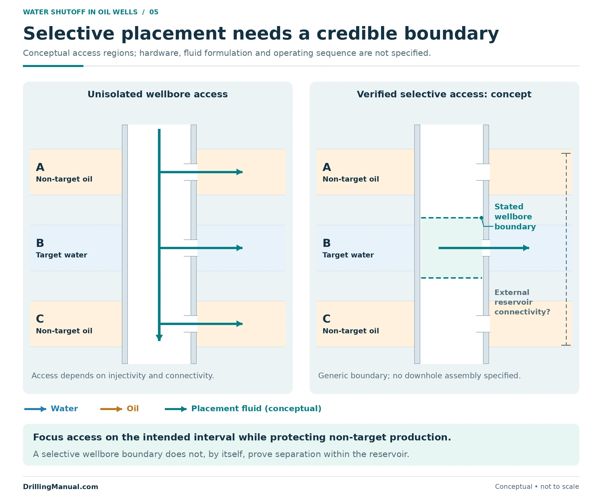
Selective wellbore placement and reservoir selectivity are separate questions. Isolating an interval at the wellbore can help control the entry location, but communication through the formation still requires assessment. Conversely, a treatment intended to favor water reduction needs evidence for that effect; it should not be treated as automatically harmless to every oil-producing interval. [1]
Screen the proposed system against the relevant rock, fluids, temperature exposure and required performance. For chemical systems, the source discusses the value of core-flow testing and explains why bulk-gel appearance alone does not fully establish performance in the rock. It also notes that injection can change the near-wellbore temperature, which matters for systems that react after placement. No generic formulation, volume or setting time can replace that evaluation. [1]
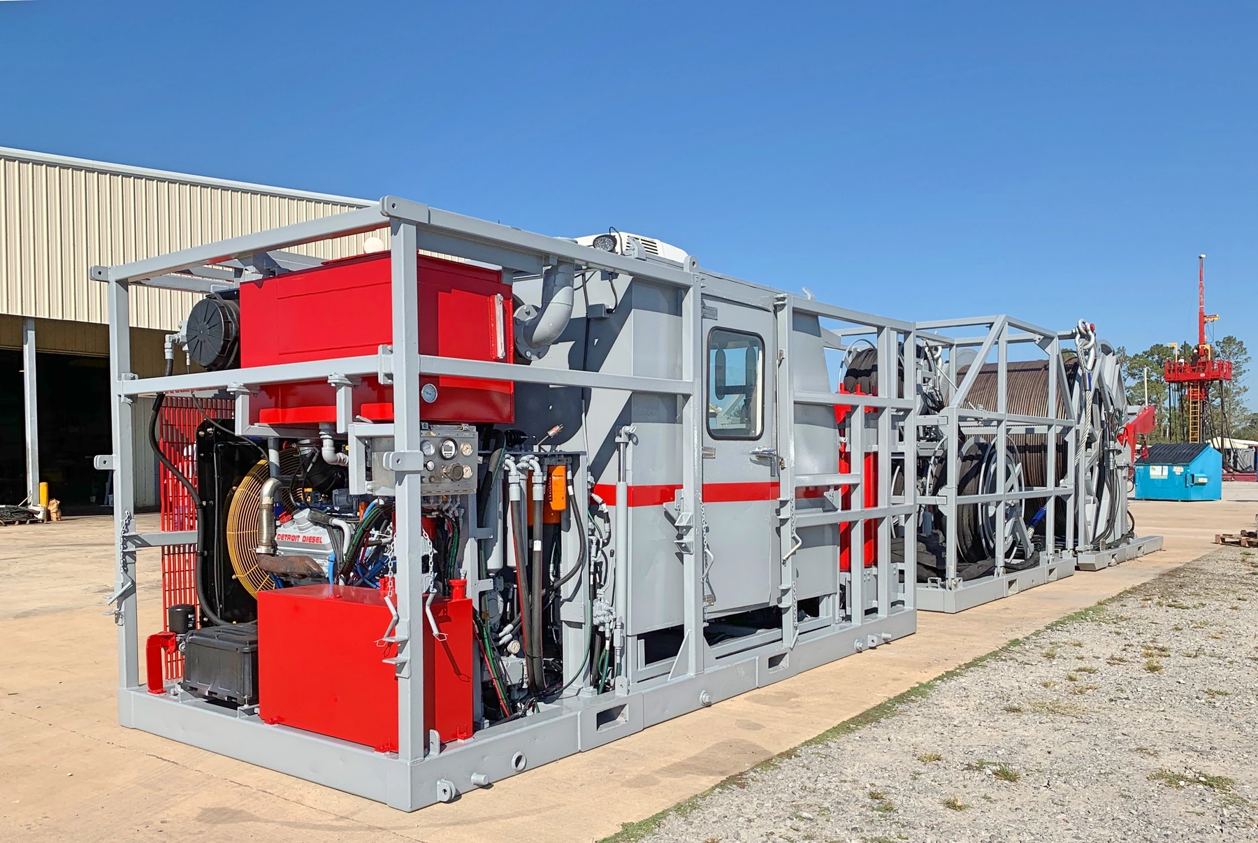
Photo: Dannybsnubbin / Wikimedia Commons, CC BY-SA 4.0. Resized and converted from JPEG to WebP; no crop or content alteration.

The desired reduction in a target’s flow capacity must be kept separate from unintended damage to useful inflow. The formation damage guide provides the broader productivity context. Here, the design question is whether the selected effect and placement preserve the oil contribution the job is intended to retain. [1]
Worked Example: Water Removed and Oil at Risk Are Different Quantities
Consider one hypothetical well with three allocated producing intervals. All rates below are on the same stated surface-volume basis and at one stable operating condition. These invented values illustrate accounting; they are not field measurements or predicted treatment results.
| Interval | Oil, bbl/d | Water, bbl/d | Water cut |
|---|---|---|---|
| A | 120 | 30 | 20.0% |
| B | 80 | 720 | 90.0% |
| C | 100 | 50 | 33.3% |
| Whole well | 300 | 800 | 72.7% |
Water cut = water rate ÷ (oil rate + water rate) × 100. It is a liquid-rate fraction on a consistent measurement basis; gas is not included in this two-liquid calculation. Whole-well water cut is calculated from the summed rates, not the simple average of the interval percentages.
Now assume complete isolation of interval B, with the contributions from A and C held unchanged for this arithmetic exercise. Remaining oil is 120 + 100 = 220 bbl/d. Remaining water is 30 + 50 = 80 bbl/d. The resulting calculated water cut is 80 ÷ 300 × 100 = 26.7%.
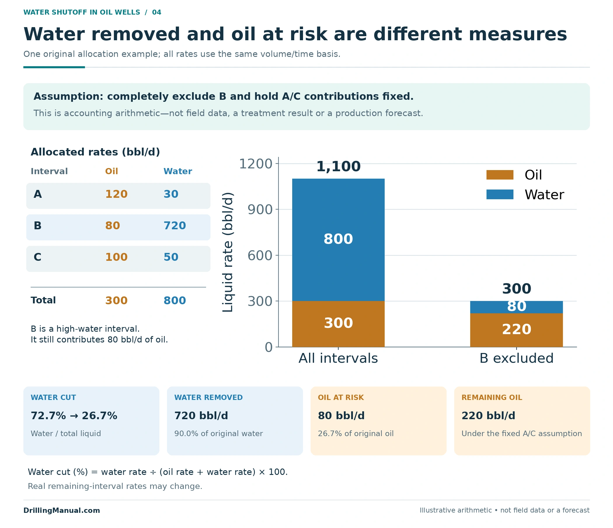
Under that assumption, the excluded interval accounts for 90% of the original water and 26.7% of the original oil. Its 90% water cut did not make its oil contribution zero. The decision needs both quantities, together with the relevant operating and treatment constraints.
The arithmetic is not a post-treatment forecast. Petroleum Well Construction explains that closing one interval can change the conditions seen by those remaining open, and that a water-contributing interval may still contain useful oil. Actual post-treatment rates require an appropriate well/reservoir assessment and subsequent measurement. [1]
Reassess the Remaining Intervals After Isolation
Removing an inflow path changes the producing system. The remaining intervals may operate at different conditions, and another interval may become a more important water contributor. Treat the before-job allocation as the starting evidence, not a permanent allocation that must survive the intervention. [1]
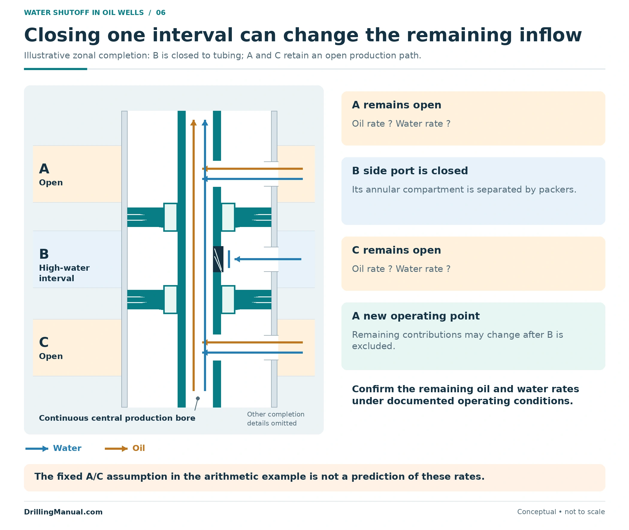
This is why the proposed objective should state both the target effect and the expected remaining production. “Close interval B” describes a local completion function. “Reduce water while retaining a defined oil contribution” describes a production objective. Demonstrating one does not automatically establish the other. [1]
Use a Candidate Review That Makes the Unknowns Visible
The following six-part review is an original organization of the books’ diagnostic, design and placement considerations. Record the evidence behind each answer and the uncertainty that could change the choice. [1, 2, 3]
- Source and path: What explains the water entry, and what alternatives remain?
- Interval contribution: How much oil and water are associated with the target?
- Connectivity: Could water reach another open interval or bypass the intended treatment?
- Access and placement: What physical boundary or delivery arrangement supports the proposed target coverage?
- Conditions and compatibility: What supports treatment performance in the actual rock, fluids and temperature environment?
- Objective and evaluation: What oil, water and functional measurements would establish an acceptable result?

If the leading alternatives require different treatment targets, collecting the missing evidence may be more useful than selecting a material immediately. Equally, if a complete seal would exclude too much useful oil, a different treatment objective or continued water management may deserve evaluation. Neither conclusion can be made from water cut alone. [1]
Evaluate Water Reduction, Oil Retention and Persistence
Define success before the intervention. The source identifies problem characterization, treatment design and effective placement as linked requirements, and it treats expected treatment life as part of the design. A lower water-cut number is only one observation in that evaluation. [1]
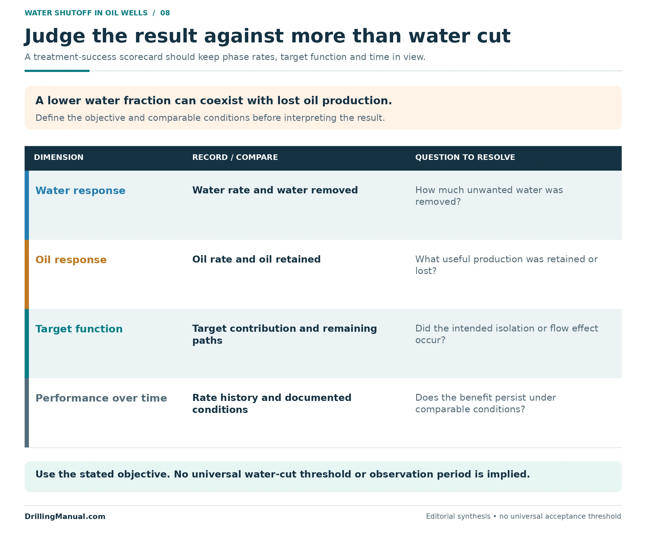
Compare oil and water rates alongside the recorded operating conditions. Separately assess whether the target function was achieved, whether the evidence still supports the proposed path, and whether the result persists. A drop in total liquid production can reduce water while also losing oil; a changing water contribution can indicate that the original system has evolved. These are reasons to examine the measured response rather than rely on one headline percentage. [1]
Where the intervention also concerns completion integrity, verification must address that function within the applicable well program. The well integrity guide provides the wider barrier and monitoring context. A production-rate improvement and a demonstrated integrity function are separate findings. [2, 3]
Frequently Asked Questions
What Is the Best Water Shutoff Method for an Oil Well?
There is no single method for every well. The choice depends on the supported water path, interval contributions, completion access, placement requirements and acceptable effect on oil. A plug, a sealing treatment and a relative permeability modifier address different objectives. [1]
Does High Water Cut Mean the Wettest Interval Should Be Shut Off?
No. First establish the water route and the interval’s oil contribution. The wettest interval may still supply useful oil, and its isolation may change the response of other intervals. The worked example quantifies that tradeoff without predicting a field result. [1]
Can a Bridge Plug Stop Water Travelling Behind Casing?
Only if the resulting isolation actually interrupts the relevant production route. A closure inside casing does not automatically block an external channel that feeds open perforations elsewhere. The complete path and remaining openings determine the required boundary. [1, 2]
Can a Production Log Identify the Original Water Source?
It can help locate and allocate inflow, but an entry depth need not be the source depth when water travels behind casing. Combine the relevant measurements with completion and reservoir evidence. Multiphase behavior and measurement conditions affect the interpretation. [3]
Do Water Shutoff Chemicals Leave Oil Production Unchanged?
That cannot be assumed. A zone sealant shuts off all target production; ordinary permeability reduction can affect both phases. A relative permeability modifier aims for a greater water-permeability reduction, but that is not a guarantee of unchanged oil flow or indefinite benefit. [1]
Can a Chemical Treatment Be Placed Without Zonal Isolation?
The book describes placement without mechanical isolation, but its suitability depends on which intervals are open and the treatment’s effect on them. Reaching the well does not establish target-only placement. Useful non-target inflow and reservoir communication must be assessed. [1]
Does a Lower Water Cut Prove That the Treatment Succeeded?
It does not establish the full result. Compare the actual water reduction, oil retained, target function and persistence under documented conditions. The three-interval example shows why a large water-cut reduction can accompany a meaningful loss of oil contribution.
Why Can Water Production Return After a Treatment?
Possible explanations include ineffective target coverage, treatment-performance loss, an alternative route or changing inflow from other intervals. The explanation needs evidence from the job and subsequent production; recurrence alone does not establish which mechanism occurred. [1]
Technical References
[1] Hardy, Mary, and Thomas Lockhart. “Water Control,” Chapter 17 in Petroleum Well Construction, edited by Michael J. Economides, Larry T. Watters and Shari Dunn-Norman; John Wiley & Sons. Consulted 903-page digital copy, especially PDF pp. 828–837, 841–842, 844–853 and 856–859. Used for water-production mechanisms, diagnosis, treatment objectives, oil-production consequences, placement and performance evaluation. Page references follow the visible numbering in this digital copy. Historical field statistics, discharge limits, commercial formulations and pumping examples are not adopted as current recommendations.
[2] Perrin, Denis, with Michel Caron and Georges Gaillot. Well Completion and Servicing. Editions Technip, English edition, 1999. Chapter 5, especially printed pp. 255–257 / physical PDF pp. 267–269. Used for diagnosing water-producing intervals and distinguishing completion-related water paths from reservoir inflow before choosing an intervention.
[3] Schlumberger. Cased Hole Log Interpretation: Principles/Applications. Copyright 1989; fourth printing, March 1997, in the consulted copy. Chapter 4, especially printed pp. 4-1–4-5 and 4-16–4-19 / physical PDF pp. 68–72 and 83–86; printed p. 1-1 / physical PDF p. 12 for cement-evaluation scope. Used for production-log interpretation, multiphase and measurement limits, and the distinction between fluid source and wellbore entry.
Engineering explanations come from these books. The tables, numerical example, review framework and drawings are original educational constructions. Photograph sources and reuse information are stated in their captions.