PDC Drill bits have been used extensively and successfully over various formation types. The lack of rotating parts leads to greater life expectancy, as long bit runs are achievable with resultant time and cost savings (check also drilling cost per foot). Due to its increased cost, drilling engineers shall thoroughly review the economics of running a PDC drill bit before bit selection.
PDC Drill Bit Design Features
PDC bits have several significant design features that enhance their ability to drill:
- The lack of internal moving parts reduces bit failure potential.
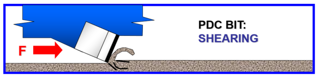
- Since it fails the rock by shearing, it will require less drilling effort than the cracking and grinding principles used in roller cone bits.
- No requirement for high-bit weights. (more applicable in deviation control.)
- The low-weight requirements and no internal moving parts make them well-suited for turbine drilling.
Gaining more experience with the bit will enhance design features.
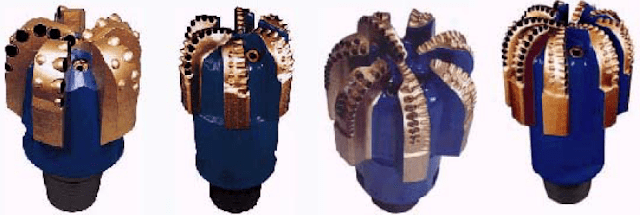
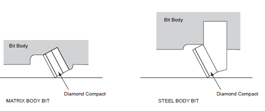
Bit manufacturers integrate the PDC blank into their respective bit designs (Fig.1). Variations in designs include the number and placement of the blanks, jet structure, and watercourse development. In some applications, PDC bits will drill 3-4 times the footage of a conventional roller bit at 2-3 times the drilling rate if sticky formations do not pose problems. For example, 18,000-20,000 ft wells in South Texas typically complete in 70-80 days using PDC bits vs. 120-130 days with conventional roller bits.
The manufacturing of PDC bits is either with a machined steel or a matrix body process. The matrix process is similar to the manufacturing of diamond bits. The cutters are attached to the bit by proprietary techniques. Matrix bodies appear to be more erosion-resistant.
The shape of the PDC cutters is becoming an important consideration. Most manufacturers use the original circular design. However, there are many research and development efforts to enhance the design and improve drilling performance.
The Major Applications OF PDC Drilling Bits:
- PDC bits are typically helpful for drilling long, soft, to medium shale sequences with low abrasivity. Such formations typically exhibit high ROP and extended life, allowing entire drilling sections on one run.
- PDC bits are not usually appropriate for a highly abrasive well or cemented sand sequences. Drilling tight siliceous formations may lead to PDC chipping and breaking. In addition, it may result in less than expected ROP and bit life.
- Drilling heterogeneous formations containing alternating shales and/or shale limestone sequences encourage the application of Hybrid PDC bits. This bit incorporates the use of backup diamond studs behind the PDC cutter.
- When drilling harder abrasive strings, the diamond stud absorbs the increased weight required to drill the stringer, preventing premature damage and wear to the PDC cutter.
- Drilling hard formations may require the use of bladed hybrid PDC bits. The deep watercourse on these bits enables optimum fluid flow across the cutter to reduce the friction temperatures induced efficiently. This efficient cooling will help minimize the fracture of the PDC cutters.
- It is a good practice to consider eccentric PDC bits when drilling mobile plastic formations such as salt sections. These bits have successfully prevented stuck pipes in areas with salt flow problems.
- Drilling engineers may consider long tapered profile bits when planning for mud motors or turbines. In addition, radial jetting bits reduce the potential for friction-induced high cutter temperatures when run on a motor or turbine, reducing the cutter’s temperature degradation.
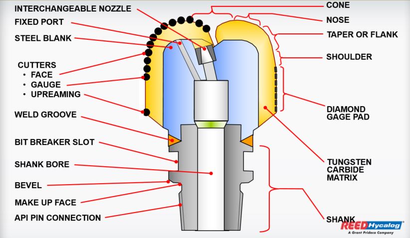
PDC Drill Bit Design & Components
What are The Main Steps Of PDC Bit Design are:
- Bit Body Material Design
- PDC Cutters Material
- PDC Cutter Geometry
- Cutter Shape
- Bit Profile Geometry
PDC Drill Bit Body
The bit body design may be:
- Steel Body: The bit body is forged or milled from steel (steel-bodied bits). The cutters on a steel body bit are manufactured as studs. The stud can be set with a fixed back rake and/or side rake (will be discussed later). Field experience with the steel body bit indicates that face erosion is a problem, but many overcome this by applying a hard-facing compound to some extent. Steel body bits also tend to suffer from broken cutters due to limited impact resistance. This limited impact resistance is because there is no support to the stud cutter. Many prefer tham as they can be easily repaired but suffer from erosion.
- Matrix Body: PDC Matrix Body drill Bits are constructed in a cast from tungsten carbide (matrix bit). They are more resistant to erosion but are prone to bit balling in soft clay formations due to their low blade height compared with steel-bodied bits. Matrix body bits have an economic disadvantage because the raw materials used in their manufacture are more expensive.
Fortunately, steel and matrix PDC drill bits rapidly evolve, and their limitations are diminishing. As hard-facing materials improve, steel bits are becoming significantly well-protected with materials that are highly resistant to abrasion and erosion. At the same time, matrix materials’ structural and wear-resisting properties are also rapidly improving, and the range of economic applications suitable for both types is growing.
Today’s PDC drill Bits Design as a matrix has little resemblance to that of even a few years ago. Tensile strengths and impact resistance have increased by at least 33%, and cutter brazes strength has increased by ≈80%. At the same time, geometries and the technology of supporting structures have improved, resulting in robust and productive matrix products.
Cutters Material
PDC Cutters are made from carbide substrate and diamond grit. The high heat of around 2800 degrees and high pressure of approximately 1,000,000 psi forms the compact. A cobalt alloy also acts as a catalyst for the sintering process. The cobalt helps bond the carbide and diamond.
Please visit the PDC Bit Cutters Material article for more detailed information.
Number of Cutters
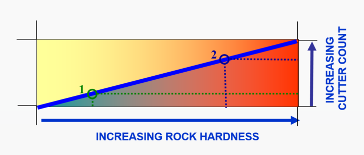
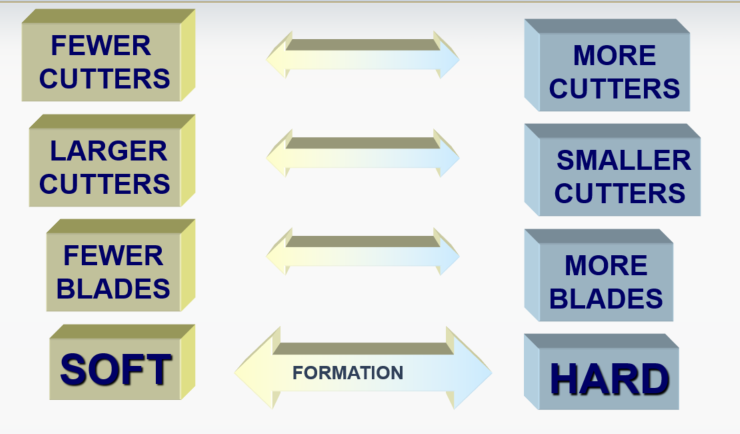
We usually use fewer cutters on soft PDC bits as each cutter removes a greater depth of cut. For harder formations, it is essential to use more cutters to compensate for the smaller depth of cut.
PDC Drill Bits – Cutters Size
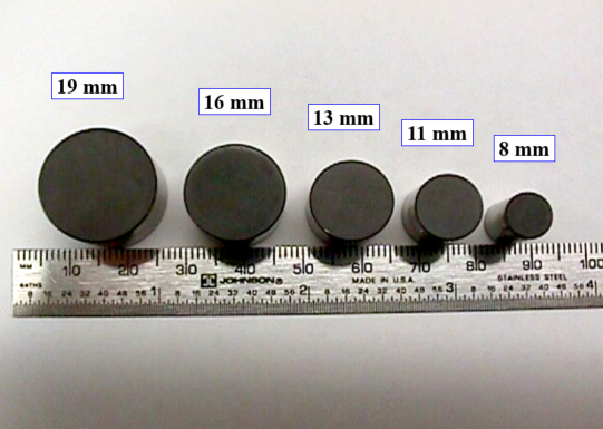
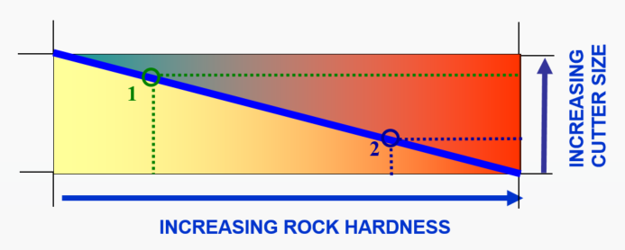
For softer formations, we typically choose larger cutters than in harder formations. Usually, the standard range of sizes is from 8 mm to 19 mm on anyone bit.
Cutter Rake
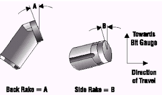
We generally describe the cutter rack design orientation by back rake and side rake angles.
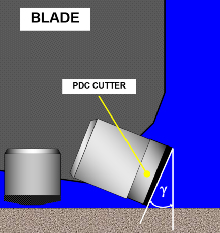
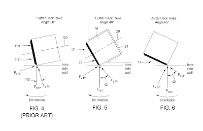
- The cutter back rake is the angle presented by the face of the cutter to the formation and is measured from the vertical. Back rake angles vary between, typically, 15° to 45°. They are not constant across the bit, nor from bit to bit. The magnitude of the cutter rake angle for PDC drill bits affects Penetration Rate (ROP) and cutter resistance to wear. As the rake angle increase, ROP decreases, but the resistance to wear increases as the applied load is now spread over a much larger area. PDC cutters with small back rakes take large depths of cut and are therefore more aggressive, generate high Torque, and are subject to accelerated wear and greater risk of impact damage.
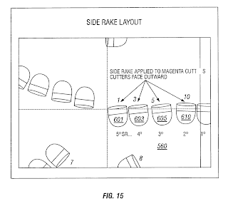
- The cutter side rake is an equivalent measure of the orientation of the cutter from left to right. Side rake angles are usually small. The side rake angle assists hole cleaning by mechanically directing cuttings toward the annulus.
Cutter Shape
The most common PDC Drill Bits shape is the cylinder, partly because it is easier to arrange cylindrical cutters within the constraint of a given bit profile to achieve large cutter densities. Electron wire discharge machines can precisely cut and shape PDC diamond tables (Fig. 8). Nonplanar interface between the diamond table and substrate reduces residual stresses. These features improve resistance to chipping, spalling, and diamond table delamination. Other interface designs maximize impact resistance by minimizing residual stress levels.
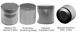
Specific cutter designs incorporate more than one diamond table. The interface for the primary diamond table is engineered to reduce stress. A secondary diamond table is located in the high-abrasion area on the ground-engaging side of the cutter. This two-tier arrangement protects the substrate from abrasion without compromising the structural capability to support the diamond table.
Highly specialized cutters are designed to increase penetration in tough materials such as carbonate formations. Others include engineered relief in the tungsten carbide substrate that increases Penetration Rate (ROP) and reduces the requirement for Weight On Bit (WOB) and Torque or beveled diamond tables that reduce effective cutter back rake and lower bit aggressiveness for specific applications.
Cutter Exposure
The Cutter exposure is the amount the cutters protrude from the bit body. It is essential to ensure that the exposure is high enough to allow good cleaning of the bit face but not so high as to reduce the mechanical strength of the cutter.
High exposure of the cutter provides more space between the bit body and the formation face, while low exposure provides good backup and support to the cutters.
Number of PDC Drill Bit Blades
Using the same analogy for roller cone bits, a PDC bit designed for soft rocks has fewer blades (and cutters) than one designed for hard rocks.
- The soft formation PDC bit will have a large junk slot area to remove the large volume of cut rock and reduce bit balling in clay formations.
- A hard formation PDC bit with many blades requires many small cutters, as each cutter will remove a small amount of rock.
Blade Height
A soft formation PDC bit will have a larger blade height in its design than a hard PDC bit, with a consequent increase in the junk slot area. Higher blades can be made in steel-bodied- bits than matrix bits because of the greater strength of steel over that of the matrix.
Blade Geometry Design
Bit blades range from straight to complex curve shapes. Experience has shown that curved blades provide excellent stability to the bit, especially when the bit first contacts the rock.
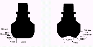
PDC Drill Bit Profile Design
Bit profile affects both the cleaning and stability of the PDC bit. The two most widely used profiles are:
A – Double cone: The double cone profile allows placing more cutters near the gauge giving better gauge protection and allowing better directional control.
B- shallow cone: The shallow cone profile gives a faster Penetration Rate (ROP) but has less area for cleaning.
Generally, a bit with a deep cone will tend to be more stable than a shallow cone.
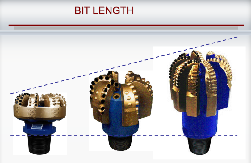
Bit Length
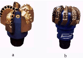
The bit length selection is important for steerability. Shorter bits are more steerable. The two bits on the left below Figure are sidetrack bits (also check: sidetrack drilling) with a short, flat profile.
The ‘Steering Wheel’ bit on the right is designed for general directional work.
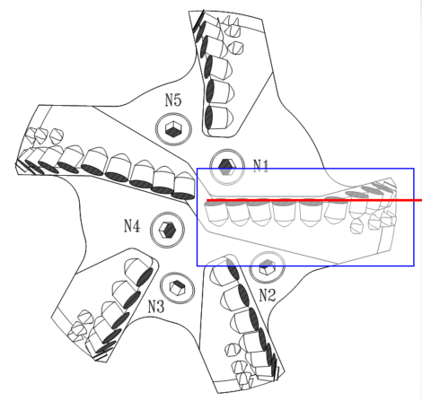
As discussed, the most significant amount of work is done on the heel and gauge of the drilling bit. PDC drill bits that wear more on the gauge area will leave an Under gauge Hole, which will require reaming from the next bit. Reaming is time-consuming and costly and, in some cases, can destroy an entire bit without drilling a single foot.
Hence maintaining a gauge is very important. We can position one or more PDC cutters in the gauge area. Pre-flatted cutters are used to place more diamond tables against the gauge. Tungsten carbide inserts, some with natural or synthetic diamonds embedded in them, may be placed on the flank of bit 1.
A significant advantage of fixed cutter bits over roller cone bits is that there may be an extension for the gauge on fixed cutter bits to a more considerable length of the drill bit.
Conclusion
When we put all of the above PDC Bit Design features together, you will find :
- PDC drill bit designs depend on high or low RPM applications, i.e., turbine vs. rotary drilling. Turbine applications use more blanks to compensate for friction-related wear considerations. The tapering of the PDC bit allows the placement of the cutters. PDC bits for rotary applications have fewer cutters and a flat design.
- Rotary-designed PDC bits often use nozzles to allow fluid circulation for cuttings removal and cooling of the bit. Manufacturers may vary the number and distribution of the nozzles. A tendency for applications in Water-Based Mud is to use small jets to achieve high fluid velocities. This feature is not as significant in Oil Based Mud applications.
- The PDC bit on the extreme left of the below Figure is a light set bit with a few high blades and a few large cutters with small back rake angles. Thus light set bits typically have a few high blades, with few large cutters, probably with a low back.
- For hard rocks, PDC bits will have more blades, with smaller and more numerous cutters, and this trend continues to the heavy set bits on the extreme right of the below Figure.