The Objective Of the Gas Show article is to:
- Firstly, define the origin of gas shows.
- Secondly, define gas shows.
- Thirdly, describe the types of gas shows detected from the drilling fluid.
- Fourthly, define the sources of gas shows detected in the drilling mud.
- Fifthly, describe various factors which affect the gas show analysis.

1 Origin Of Gas Show
The general definition of a “gas show” is a significant occurrence of hydrocarbon gases detected from the mud stream and identifiable as the result of the drilling of a specific increment of formation.
One of the prime objectives of surface logging is to plot those gas readings. Also, they are liberated from the drilled formation in conjunction with data relevant to their interpretation. Using the data, it is then possible to reconstruct the composition and mobility of the reservoir hydrocarbons.
To reconstruct a picture of the in-situ fluids and the type of fluids the formation may produce. And, it is necessary to study gas magnitude and composition in the mud stream and cuttings, geological and physical character of the cuttings themselves, and changes in the drilling process and Circulating System which may affect or be affected by formation fluid behavior.
Prior to examining the factors affecting gas shows, some definitions are in order:
A True Zero Gas
The value seen by the gas detector when pure air is passed across the detecting element, for calibration purposes.
B System Zero Gas
The value of gas (by a gas detector) when circulating under normal conditions, meaning a clean, balanced borehole with Drill Pipe in the hole and rotating, but with the Oilfield Drilling Bit off-bottom and with no vertical movement. Under such conditions, some gas will be present in the sample drawn from the mud stream. But it will represent only contamination or recycled hydrocarbons in the mud. This value is taken as the baseline above which all gas readings are taken for drafting on the FEL. The system zero will vary continually with additions to the mud system, and with mud and ambient temperature. The value must be regularly reestablished to allow accurate, consistent gas logging.
C Background Gas
When drilling through a consistent lithology, it is common for a consistent gas value to be recorded. Certain lithologies (for example, overpressured shales) may show considerable rapid variation in background gas but usually with some consistent average value.
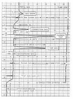
Gas Show Definition
A “gas shows” is any deviation in gas amount or composition from the established background. This may or may not accompany a change in lithology, may or may not be as a result of the drilling process, may or may not indicate a significant or economic hydrocarbon accumulation. It is the responsibility of the Logging Geologist to interpret the gas show and to determine its cause and significance.
Types of Gas Show
“What is a good gas show?” is a common question asked of the logger. The answer to this is complex and relates to many factors beyond the simple number of “gas units” seen. To decide whether a gas show is “good” or “poor” (i.e. whether or not a significant hydrocarbon accumulation is indicated) requires a total evaluation of all FEL parameters plus consideration of the many other variables.
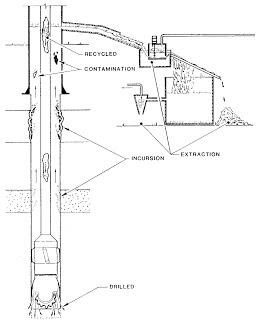
Sources of Gas Show in the Mud
Gas (detected in the Drilling Mud stream) can originate from a formation, via a number of mechanisms. It is necessary for the geologist to isolate and monitor these causes to draw the appropriate conclusion. Gas (originating from other sources or only indirectly from the formation) will also be seen in the mud stream. These must, if possible, be recognized and removed from consideration.
A Gas from drilling
This is often referred to as “liberated” gas since it is liberated into the mud stream from the crushed cylinder of formation (from the drilling).
B Post-drilling gas
Sometimes referred to as “produced” gas, since it is gas that has flowed from the formation into the borehole in the same manner as if the formation were to be produced. Post- drilling gas, i.e. gas entering the borehole from the borehole wall or bottom when drilling is not taking place, is of two distinct types.
a. When pipe is pulled from the hole, or circulation halted, a condition of underbalance may exist at some point in the borehole. A negative differential pressure will cause fluid to flow into the borehole from the formation.
b. In a condition of balance or even with some overbalance there will be a continual diffusion of fluids between the formation and the borehole. This will be encouraged by removal of filter cake by pipe movement and by the flow of drilling fluid past the exposed borehole wall.
C Recycled Gas
Not all the gas entrained in the mud stream will be removed at the gas trap. If insufficient degassing takes place at the surface, drilling fluid containing gas will be pumped back into the borehole. Travel of the light gas-cut mud past gas-bearing formations in the borehole may encourage diffusion of more gas into the mud.
D Contamination Gas
Gas resulting from the addition of petroleum products to the mud or from the degradation of inert Mud Additives can result in the anomalous gas show. Similar anomalies may result from the presence in the Circulating System of spotting fluids from previously problem areas or formations.
Factors Affecting Gas Show
Although the crushed cylinder of formation produced by drilling releases a quantity of gas which may be detected at the surface, this gas is subject to many influences between the formation and the gas detector.
A) Downhole Influences that affect Gas Show
- Flushing
- Fluid Incursion
Flushing
It is well known that when borehole pressure exceeds formation pressure and permeability exists, the drilling fluid will tend to be flushed into the formation. If the mud-solids diameter is large enough, only fluid filtration will result. Such flushing commonly causes little formation damage since invasion takes place only a short distance into the formation.
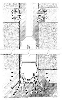
However, where effective porosity is low, a small volume of fluid will cause a large amount of flushing. Displacement of gas some distance from the borehole can reduce the reservoir’s gas saturation and effective permeability to gas close to zero in the vicinity of the borehole. Thus a zone which gives good gas shows when drilled will appear to be water-bearing or recover only mud filtrate when wireline logged or tested.
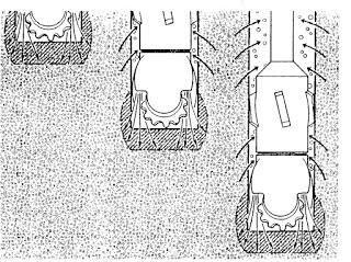
Flushing will also take place at the bottom of the hole when an overbalance exists. In this circumstance no permanent mud filter cake can be formed due to the continuous action of the bit. Flushing below the drill bit will have the most effect when the reservoir has high permeability and effective porosity. The positive differential pressure combined with the high impact force of the jet nozzle pressure drop will force mud filtrate into the formation ahead of the bit.
When the formation is eventually drilled, little or no gas is liberated. At the surface, a flat unresponsive gas curve will be seen which may even indicate less gas than in nearby lithologies. Since permeability is high, the reservoir will return to it’s natural state soon after drilling, and an apparently waterbearing reservoir will later be wireline logged or tested as productive.
Good drilling practices of minimizing Mud Density and water loss will be advantageous in reducing flushing. On the FEL, the following information should be recorded for proper interpretation of possible flushing:
- Pump Pressure
- Jet Nozzle Sizes
- Mud Rheology
- Mud Density & Drilling ECD
- Estimate of Pore Pressure
- Water Loss
- Lithology Description including Visual Porosity
A formation indicating high porosity and permeability confirmed by a good rate of penetration, which indicates little or no gas in either mud or cuttings, should be suspected as being flushed prior to drilling – especially where an overbalance exists. However, the possibility does exist that the formation contains only water without even gas in the solution. This possibility can be confirmed or rejected by monitoring mud salinity.
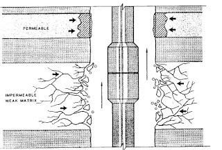
Fluid incursion
The incursion of fluid into the borehole may result from a number of causes, some but not all of which result from an underbalanced condition of either a temporary or permanent nature. Where an underbalanced drilling condition exists, there is a natural tendency for fluid to flow from the formation into the borehole. When the formation has good porosity and permeability, this flow may be massive and a Kick could occur ( check also Kick warning Signs)
.
Where an underbalance, sufficient to cause a kick, exists but there is insufficient permeability to sustain a massive fluid influx, a steady fluid “feed-in” may result. If this minor flow is from discrete formation already cut, it will be noticeable and produce a sustained minimum gas background even when circulating, but not drilling. If the “feed-in” is from the formation currently being drilled, then as a greater and greater area of formation in the borehole wall is exposed by drilling, increasing flow will take place.
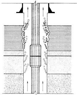
If this is the case, the mud gas will exhibit a sustained minimum when circulating but will consistently rise as drilling proceeds. Cuttings gas will inevitably be high, relative to mud gas, since the lack of only permeability is preventing the feed-in from becoming a Kick.
When permeability is effectively absent (e.g. clays and shales) even minor feed-in cannot take place. Fluid pressure in the rock will gain access to the borehole by the opening of pre-existing microfractures and partings in the rock. The result will be the caving or sloughing of rock fragments into the borehole, accompanied by a small amount of gas. As above, a minimum gas background and, in this case, cavings recovery will exist even when circulating without drilling.
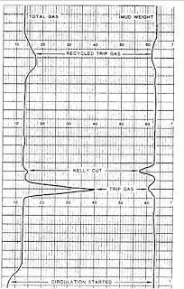
At connections and trips (check also tripping pipe procedures), the reduction in bottom-hole pressure may cause a temporary underbalance condition. Connection gas is a gas shows resulting from this momentary underbalanced, due to pump shutdown and/or pipe movement. It can be recognized by the occurrence of discrete gas shows appearing at, or slightly less than, the lag time after circulation recommences.
Fluid incursion into the borehole can also occur when there is a balanced or even slightly overbalanced condition. This situation is associated with the flushing effect already mentioned. Where a sufficient thickness of formation has been cut and vertical permeability exists, it is possible for the displaced formation fluids to be produced into the borehole at some point above bit turbulence. The effect of this, during normal drilling, will be to effectively delay the appearance of a gas shows until some time after the formation is cut. This mechanism is termed “sweeping”.
B) Formation Porosity and Saturation
The amount of gas released into the mud stream from a specific interval of formation will depend upon (i) the absolute porosity, (ii) the effective porosity, (iii) the effective permeability, and (iv) the gas saturation relative to water saturation.
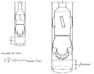
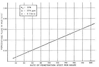
C) Drill Rate
Assuming that all other formation, mud, and drilling considerations are held constant, the amount of gas liberated to the mud system during drilling will be a function of the total volume of effective porosity exposed to the mud stream by the cutting action of the bit. This will be dependent upon the cylinder volume of formation cut. It will also vary with bit type since different bits produce different sizes of cuttings.
A formation identical in all ways will produce higher mud gas readings if drilled at a higher rate of penetration.
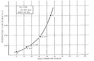
D) Bit Size and Type
The second factor, controlling the volume of formation cut, is the hole diameter. The size of the bit teeth, which is governed by both bit selection type and size, will determine the size of cuttings produced during drilling. When the cuttings are smaller and more numerous, formation fluids will be more easily liberated from non-effective porosity and inferior permeability, giving improved gas shows.
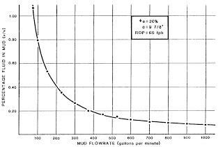
E) Flow Rate
The volume of gas or cuttings entering any volume of mud that passes across the bottom of the borehole will be a function of mud flowrate. Since surface gas logging depends upon the analysis of gas extracted from the mud, modifications to the flow rate will affect the apparent gas magnitude.
As the mud flow rate increases, the volume of gas and cuttings contained in a fixed volume of mud will decrease. Conversely, the volume of mud passing through the gas trap will increase. The net effect should be zero. In fact, the complex geometries and variable efficiencies of the components of the system will introduce some variations, but the overall effect is probably not great. Furthermore, mud flow rate will not vary greatly within any hole size or in relation to hole size within hole sections. This further removes the severity of this effect.
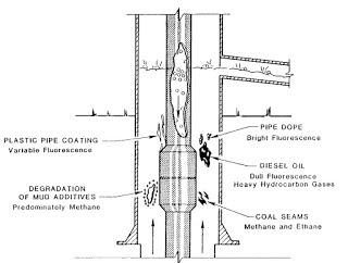
F) Borehole Contamination
A common source of gas contamination is the degradation of organic-based mud additives (e.g. lignosulfonate). These tend to degrade with the severe changes in temperature, pressure, and with the catalytic support of the clay ion exchange sites on the mineral matrix. The common by-product of degradation is methane, although more complex hydrocarbons may also be present, depending on the additive.
The second major cause of contamination is the addition of small amounts of crude or diesel oil added to the mud as a lubricant. Crude oil may be a serious problem since it will mask later oil shows. The more commonly used diesel oil is much less of a problem since the gases liberated from it and its appearance in samples are untypical for a natural crude oil.
The gas content, due to contamination of the mud, will continually vary. As additions are made and recycling occurs, peaks will develop in the system. It is important that the logging geologist regularly re-establish the system zero, above which gas shows are determined.
G) Surface Influences
Although there are many factors which can affect the liberation and transport of gas to the surface, it is readily observed that the most important factors controlling the final magnitude of a gas shows are the rig’s surface system and the extraction, pneumatic, and detection systems of the logging unit.
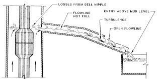
Flowline
It is well known that a high degree of degassing takes place in the bell nipple and flowline. Loss of gas in the flowline will be especially high where:
- The flowline is not filled with drilling fluid
- Changes in slope promote turbulence
- Sections of the flowline are open to the atmosphere
- The flowline enters the possum belly above the mud level
The geometry of the ditch will have a considerable effect on the volume of mud and gas available to the gas trap. Location of flowline entry, direction of major flow, and degree of turbulence will all affect the efficiency of the gas extraction system.
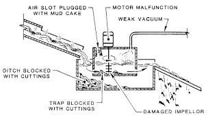
Gas Trap
The efficiency of gas traps can vary between 30% and 70% depending upon design, location, and mud properties, but most importantly upon careful maintenance and good operation. The trap and its immediate surroundings must be kept clear of cuttings debris, settled debris, or mud caking, all of which may restrict or modify the flow of mud and air through the trap.
The mechanical efficiency of the trap is controlled by the rotational speed and surface blade area of the trap impeller, strength of vacuum, and flowrate of air from the trap. Even when installation and maintenance of the gas extraction system ensure maximum mechanical efficiency, there will be variations in the overall efficiency of the extraction and the magnitude of gas shows. This will depend on the composition of gas present, distribution of gas in the mud, and mud flowrate.
In summary, the magnitude of gas shows recorded by the logging unit’s gas detection system and their interpretation will depend on numerous factors, which include:
- Formation characteristics – porosity, permeability, fluid saturations
- Flushing effects – overbalance, water loss, formation porosity/ permeability
- The volume of formation cut – controlled by drill rate, bit diameter
- Size and nature of cuttings – controlled by bit design
- Flowrate – controlled by Pump Output and nozzle size
- Produced, recycled and contaminated gases in mud
- Loss of mud and gas at the surface – flowline, ditch characteristics
- Gas trap efficiency
- Vacuum system and gas detection efficiency and calibration
Normalization and ratio techniques have been employed to account for as many of the variables as possible so that gas readings can be better compared between wells.
Ref: Baker Hughes Mud Logging Book