ECD / Equivalent Circulating Density is an important parameter to monitor in the drilling process of a well, especially in horizontal & HPHT wells. In this article, our objective is as follows: ECD Definition, the calculations & formula of theoretical ECD in Drilling & to explain the parameters that influence ECD. You can also download the ECD calculation spreadsheet at the end of the article.
Why Do We Need To Control The ECD In Drilling?
- Most importantly, it reduces the risk of fracturing/losses to the formation. In some cases, this has led to the loss of weeks of operational time and substantial volumes of mud (up to 10,000 bbls). Mud Loss can also lead to well-control problems.
- To prevent well ballooning/supercharging of the formation and thus eliminate the loss/gain scenario.
- Minimization of hole instability due to pressure fluctuations.
- Minimize the risk of differential sticking.
- The increased costs of a well (check also oil well drilling well cost per foot) with problems may make the well uneconomic, leading to the loss of future opportunities.
In Which Drilling Wells Is The Control of ECD Most Important?
- In drilling ERD/horizontal wells where the ECD increases with measured depth, the fracture gradient does not increase significantly due to little change in the TVD.
- HPHT wells where the drilling margin (the pressure difference between the pore pressure band and the fracture pressure) is low.
- Depleted reservoirs where the fracture pressure has decreased along with the pore pressure, yet the mud weight can not be reduced due to either The presence of isolated virgin/higher pressured reservoir or
- The need to stabilize inter-bedded of overlying shales.
What Is ECD In Drilling? (EQUIVALENT CIRCULATING DENSITY)
ECD is the term given to the total pressure exerted on the wellbore. Drilling professionals generally use it to indicate when circulating increases pressure and when pipe movement (surge and swab pressures) causes an increase or decrease in pressure. It is expressed as a density in the same units as the mud weight.
Major Components That Affect ECD Value In Drilling
In summary, ECD combines raw mud density and other influences on wellbore annular pressure.
There are two components of ECD :
- Static pressure component, Mud hydrostatic pressure, and drilled solids.
- The dynamic pressure component, which is the Annular pressure loss,
- Pipe velocity,
- Inertial pressures from string acceleration and deceleration,
- Pressure to break mud gels (break circulation).
Mud Hydrostatic Pressure
Static pressure is the pressure exerted by a stationary fluid of a given density at a vertical depth. It also includes any drilled solids suspended in the mud column. It is measured in pounds of force per square inch (psi).
We can calculate this pressure from the mud density using the formula below:Pressure (psi) = mud gradient (psi/ft) * depth
- psi/ft = pounds-force per square inch per foot
Mud density can also be expressed in terms of psi/1000ft. This is denoted as pptf = pounds-force per thousand feet.
pptf shows the pressure generated by the mud for each interval of 1000ft TVD (Note: TVD, not MD). To convert a pressure gradient of psi/ft to pptf, just multiply by 1000.
i.e. 0.5 psi/ft * 1000 = 500 pptf
ECD is expressed in the same units as mud weight, i.e., pptf, ppg, psi/ft, SG.
Example
For an example of static mud pressure (hydrostatic pressure) calculation, see Fig 1.
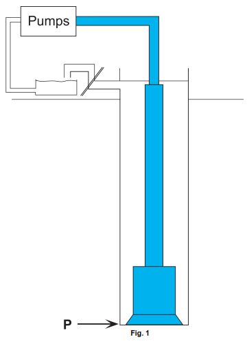
A 500 pptf mud exerts the following pressure at 6000 ft TVD:
Pressure (psi) = 500 (pptf) * 6 (thousand ft) = 3000 psi
Similarly, a 0.5 psi/ft mud exerts the following at 6000 ft TVD:
Pressure (psi) = 0.5 (psi/ft) * 6000 (ft) = 3000 psi
Bottom Hole Pressure (BHP)
Why is it important to know:
- The static bottom hole pressure and
- The dynamic bottom hole pressures.
- The static BHP must be known to avoid kicks in drilling, differential sticking, wellbore instability, and Mud Circulation Losses when the drilling fluid is not being circulated.
- Dynamic BHP must be known to avoid kicks, differential sticking, wellbore instability, ballooning, and losses when the mud system is being circulated
- Spikes (short duration increases) in either pressure can cause fracturing of the formation and losses. The spikes in the dynamic pressure are usually the cause behind the initiation of losses.
Calculating Bottom Hole Pressure
Static bottom hole pressure (SBHP)
This is the mud weight gradient multiplied by the total vertical depth.
pptf x depth in 1000’s ft (TVD)
Static pressure can be calculated easily from the mud weight (if the mud balance test procedure is correct).
Dynamic or Circulating bottom hole pressure (CBHP)
This is the Static Pressure + Annular Pressure Loss
The circulating bottom hole pressure can be presented in two ways: as a pressure (in psi) or an equivalent mud gradient in pptf.
- Pressure = psi For CBHP
- Pressure / TVD = psi / 1000ft (pptf) For ECD
Representing the BHP as a pressure gradient in pptf gives a value that can be compared with mud density and formation fracture gradient.
ECD Formula In Drilling
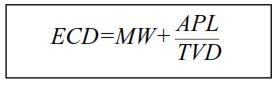
Where
- MW = mud gradient in pptf,
- APL = annular pressure loss in psi,
- TVD = True Vertical depth in ft
Measuring Bottom Hole Pressure
The most accurate means of knowing what the bottom hole pressure is is to measure it. Pressure gauges (e.g., Amerada and Quartz) run on wireline or gauge carriers used to be a means of measuring the BHP. However, running a pressure while drilling (PWD) sub is a more flexible and practical alternative.
Parameters Influencing Equivalent Circulating Density ECD In Drilling
Annular velocity
Increasing the annular velocity increases the fluid frictional pressure losses and, hence, the annular pressure loss. Consequently, the ECD expands and vice-versa.
Depth AH (along hole) and TVD
The relationship between AHD and TVD affects the ECD. For example, in a horizontal hole, the MD increases, but the TVD stays the same. This results in the ECD increasing with measured depth, although the TVD does not increase.
Rotation and Axial String Speed
As rotation increases, so does the annular pressure loss and, consequently, the ECD. This is due to Taylor vortices being set up, which extract energy from the mean axial flow and yield a higher pressure drop.
String speed in and out of the hole affects the fluid movement in the annulus, causing a change in the AV. This results in swab and surge pressures that decrease and increase the ECD, respectively. They have the same effect on the static mud gradient.
Cross-Sectional Area of Annulus – CSA
A reduction in the CSA of the annulus increases the annular pressure loss by restricting fluid flow in the annulus and thus increases the ECD. Examples of equipment causing restrictions in the annulus cross-sectional area are drill pipe tool joints, drill pipe protectors, EHP-DP, Stabilisers, etc.,
Mud Rheology
The viscosity of the mud is a measure of the frictional pressure losses the mud experiences when it is being pumped. The frictional pressure losses in the annulus are measured as the annular pressure loss. Thus, changes in mud viscosity affect the Drilling Equivalent Circulating Density ECD.
Breaking circulation (gels)
When the mud is stationary, it develops a static viscosity called gel strength. Pressure is required to start the mud moving to overcome the gel strength (break the gels). This pressure is exerted on the wellbore. The higher the gel strength, the higher the pressure required to initiate fluid movement. Once in motion, the pressure necessary to keep the fluid moving is generally less than that needed to break circulation. Consequently, the annular pressure loss will increase when breaking circulation, resulting in a higher ECD.
Solids Loading
Drilled solids in the mud increase the mud density, which can be considered an increase in mud weight or an ECD effect. It is usually regarded as an ECD effect as the solids are removed at the surface (thus are temporary), and the original weight mud is returned to the wellbore.
Suppose the drilled solids are re-ground due to poor hole cleaning. In that case, they may become so small that they can not be removed from the mud (measured as LGS – low gravity solids), in which case they will permanently increase the mud weight.
Wellbore stability problems can result in large quantities of rock caving into the wellbore, resulting in a similar increase in ECD.
Solids can settle to the low side of the hole in deviated wells to be stirred up by the later movement of the drill string (rotation after sliding or backreaming). The increase in Drilling Equivalent Circulating Density ECD due to this action can be significant.
If hole cleaning is insufficient, the quantity of drilled solids in the mud continues to increase, and so does the ECD.
The build-up of a cuttings bed reduces the cross-sectional area of the annulus, which increases the APL and, therefore, the ECD.
Barite sag
Barite Sag is a specific case of solids in the wellbore, this time not drilled solids but mud weighting solids. The barite falls out of suspension and forms dense layers of mud. When the depleted portion of mud is circulated out of the hole, the denser layers are left, which increases hydrostatic pressure and, consequently, the ECD.
Drilled Solids Loading and ECD
All of the following can significantly affect the Equivalent Circulating Density. However, they may be masked by other concurrent operations or actions. They may not be highlighted on the PWD log or considered by the drilling team at the drilling time.
- Inadequate hole cleaning
- Efficient solids (cuttings and cavings) transport causes an increase in the ECD.
- The ROP affects the amount of drilled solids in the annulus.
- Solids stirred up by string movement after motor drilling.
- Hole Cleaning procedures chosen, i.e., pills, back reaming
- Barite sag.
It is better to achieve good hole cleaning by combining a high flow rate and drilling optimization for rheology.
Inadequate Hole Cleaning
A typical shale weight is 1000 pptf ( 2.3 SG ), almost double that of a specific mud weight of 550 pptf (1.26 sg). Consequently, solids loading results in an increase in the effective mud weight.
Inadequate hole cleaning results in cuttings accumulating in the annulus, leading to a continual loading up of the mud weight. The formation of cutting beds leads to a decrease in the annular cross-section and hence increases the ECD.
Hole washouts can cause an accumulation of solids that slough downwards and bridge off where the hole is in the gauge and cause pressure increases and pack-offs. Cutting beds may avalanche, packing off and pressurizing the formation.
Efficient Drilled Solids Transport For Lower ECD
The mudflow rate is the most crucial parameter in determining effective hole cleaning.
Good hole cleaning via high flow rates leads to an increase in the suspended solids. The rise in suspension results in higher mud weight and increased annular pressure loss due to the high flow rates. Both of these contribute to an increase in the Equivalent Circulating Density.
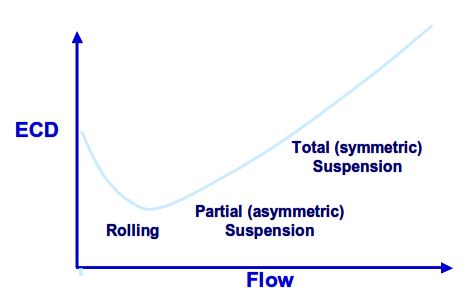
Fig 3 illustrates the effect of flow rate on hole cleaning/solids transport and how it affects the ECD.
At low flow rates, the cuttings have fallen to the downside of the hole, forming a cuttings bed, which has increased the Drilling ECD due to the annular restriction.
As the flow rate increases further, most cuttings are transported along the low side, with some suspended in fluid flow just above the bed, increasing the Equivalent Circulating Density.
At the higher flow rates, frictional pressure losses are significant, and cuttings are transported wholly suspended.
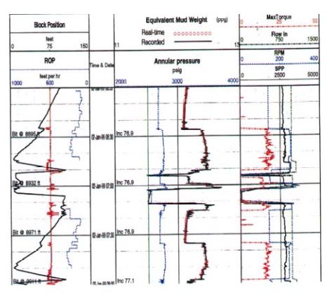
Drilling ROP & ECD
If the ROP exceeds the ability of the operations to clean the hole, then there will be a gradual increase in the ECD. This is demonstrated by the annulus pressure and equivalent mud weight curves in the PWD log shown in Fig 4
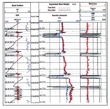
NB. In the case of long ERD wells, indications of cuttings accumulations during a drilling break can take several hours to appear in the ECD because of the long travel time in beds and not in suspension.
Rotation
As shown in Fig 5, rotation following a sliding period has caused an increase in the ECD of approx. 15 pptf.
There was a decrease in the Drilling ECD while sliding due to cuttings falling to the low side and settling out of the mud stream. Rotation stirs these cuttings back up into the flow, increasing the effective mud density.
Long periods of steering will load the annulus once rotation recommences, so it is wise to break up the sliding with rotary drilling or with circulation, rotation, and reciprocation (“TimeOut” for hole cleaning)
The PWD data can help determine the minimum RPM to effectively stir up the cuttings and clean the wellbore.
ECD Controls for the Drilling Team
| Action | Start and Stop pumps slowly. Starting the pumps slowly is the most important. |
| String Movement | Start Movement Slowly and smoothly. |
| Pump speed changes | Start and Stop pumps slowly. Starting the pumps slowly is the most important. |
| Breaking Gels | Start and Stop pumps slowly. Starting the pumps slowly is the most important |
| Backreaming | Start and Stop pumps slowly. Starting the pumps slowly is most important |
| Reaming in | This is the most likely time to cause a spike in ECD |
| Mud Condition | It should be avoided if possible. |
Tripping In (any downward pipe movement)
- Surge pressures are still significant in the casing, and tripping speeds may have to be reduced well below a ‘normal’ rate. Make sure the appropriate calculations have been made on the available software.
- Mud properties, Bottom Hole Assembly Types, BHA configurations, filter cake thickness, and Bit TFA Total Flow Area all dramatically affect the well pressures.
- Be aware of the max. Allowable pipe speeds both with and without the pumps on.
- Accelerate the pipe slowly to the maximum speed allowed, avoiding sudden movements that can create significant surge pressures.
- If tripping in with a new assy be aware of the hydraulic bypass; was a rock bit run previously?
Reaming to bottom
- The effects on the Equivalent Circulating Density increase significantly in smaller holes.
- Limit the speed, pump rate, and rpm.
- The speed of pipe movement when reaming is generally much greater than when drilling and can create considerable surge pressures.
Drilling ahead
- The ROP while sliding is limited while in rotary mode. It can be high. To limit the Drilling ECD, maintain a steady ROP and cuttings loading.
- Break up long periods of sliding with either rotary drilling or hole cleaning operations, i.e., circulation, rotation, and reciprocation.
Connections and circulating clean
- Control the string speed on the downstroke.
Breaking Circulation
- Don’t run down and kick the pumps and rotary in together to avoid pressure surges.
- If the gel strengths produce high pressures to break circulation, try starting rotation first; however, beware of disturbing unstable cuttings beds, which may fall on top of the BHA.
- Slowly build up circulation rates, e.g., 100 GPM stages.
Pumping pills
- Emphasis should be on cleaning the hole with the designed mud system by maintaining high flow rates, optimizing the rheology, and not leaving cuttings behind.
- Pills can pick up significant cuttings, dramatically increasing the Drilling ECD.
- Keep the mud in good condition – fluid loss, rheology (PV/YP/gels), mud weight.
Backreaming
- Avoid backreaming by cleaning the hole sufficiently before tripping.
- Back reaming knocks off the filter cake, which may allow losses to start at a lower pressure.
- It also causes increases in the LGS, which may cause a PV increase and, therefore, an increased Equivalent Circulating Density.
- With backreaming, there is little or no warning sign before a pack-off occurs.
Casing and Liners
- Swab and surge can be significant for all types of casing and Casing liners. The inertia in the mud system caused by cooling and gelling exacerbates the situation. Returns only start after the joint run.
Cuttings
- Good hole cleaning gives angular cuttings.
- More rounded and mushy cuttings indicate regrinding and possibly cuttings beds.
Pipe Rotation
- It is essential to stir up a cutting bed. The PWD data should be used to determine the best rotary speed. 80 – 100 rpm o.k.
- Increases the ECD.
Ref: ECD Management & Calculations Book – Fearnley Procter Group.