Upon completion of the oil well casing cementing & slurry calculations article, you should be familiar with the following:
- Calculate the amount of cement slurry for a Primary casing cementing job. (check also Cementing Design Guidelines)
- How to calculate the mixing water required for the casing cementing job.
- How to calculate the pressure required to displace & land the top plug in the primary casing cementing job
- Download the Excel Sheet to help you with casing cementing calculations steps.
Important Links To Read To Understand How To Perform Oil Well Casing Cementing Calculations
Step By Step Perform Casing Cementing Calculations & Procedures
Seven critical oil well cement calculations need to be made with every surface casing:
- Cement volume – The volume of cement needed to fill the required footage of the annulus in addition to the shoe track capacity.
- Sacks of Cement – Converting the calculated volume of cement into sacks.
- Mixing water is required for given slurries.
- Displacement fluid is mandatory for the top plug from the surface to the top of the shoe track.
- Critical Circulating Pressure – Pressure needed to lift (pump) the casing out of the hole
- Pressure to land the plug – Differential pressure is required to pump the plug (check casing running & cementing accessories) to the top of the shoe track.
- Resulting Force – The calculated hook load at the top of the casing once the plug has landed.
Required Well Parameters For Casing Cementing Calculations
- Pipe Size
- Well Fluid
- Hole Size
- Pipe Depth
- Shoe Track Length
- Required Cement fill-up
- Excess volume required (percent)
Oil Well Casing Cementing Calculations Guidelines
| pounds/force | Unit | Places Decimal |
| Density | lb/gal | 1 |
| Yield | ft^3/sk | 2 |
| Water Requirement | gal/sk | 2 |
| Length (Depth) | feet | 1 |
| Diameter | inches | 3 |
| Volume | sacks | 2 |
| Weight | pounds | 2 |
| Pressure | psi | 3 |
| Force | psi/ft | 2 |
| Capacities / Volume & Heights | ft^3/ft or bbl/ft | 4 |
| Pressure per Length | psi / ft | 4 |
| Pressure per Volume | lbs / ft^3 | 2 |
Oil Well Casing Cementing Calculations Conversion Factors
| From | Barrel | to | Cubic Feet | Divide by | 0.1781 |
| From | Cubic Feet | to | Barrel | Multiply by | 0.1781 |
| From | Lb/gal | to | Psi/ft | Multiply by | 0.05195 |
This part will show you the steps for calculating oil well casing cement slurry volume.
Given Information for Oil Well Primary Casing Cementing Calculations
- Pipe Size: 9 5/8 in 36 lb/ft
- Well Fluid: 8.7 lb/gal
- Hole Size: 12.25 in
- Pipe Depth: 300 ft
- Shoe Track Length: 40 ft
- Required Cement Fill-Up To surface
- Excess Volume Required (percent): 100%
1 Calculation for Volume of Cement Slurry
To calculate the amount (sacks) of cement required for this surface casing cementing job, you need to know the kind of cement, density, and yield.
For this example, we will utilize Class C Cement. The blend weighs 14.8 lb/gal, a Yield of 1.32 ft3/sk, and a Water Requirement of 6.3 gal/sk.
Now assume that you have circulated through the surface casing down to a depth of 300 ft and that you have a well-conditioned hole. It is mandatory to calculate the volume of slurry required for the job. This combines the slurry required to fill the annular space and the shoe joint.
A) To resolve how much slurry is needed to fill the annulus, the ft^3 /ft for the annulus is multiplied by the annulus length.
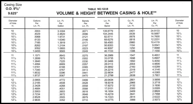
- First, refer to the “Volume and Height Between DrillPipe, Tubing, Casing, and Hole” section within the Red handbook or drilling data handbook. Look on the table for 9 5/8 in. The ft^3 /ft for this annulus is 0.3132.
- It is already given that the length of the annulus is 300 ft. Multiplying this by the ft^3 /ft value found in Step A results in the volume required to fill the annular space.
Volume of slurry In Annulus = Annulus length x Capacity (ft^3/ft)
300 ft × 0.3132 ft ^3/ft = 93.96 ft^3
B) Now, the volume of slurry in the shoe joint (or track) needs to be calculated in the last step. To resolve how much slurry is in the shoe joint, the capacity factor of the joint is multiplied by its length.
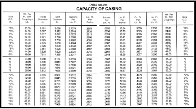
- To get this capacity factor for our cementing calculations, refer to the “Capacity” section of the Cementing Table (See also Figure 1). You need to know the OD (9 5/8 in.) and the weight (36 lb/ft) of your casing. The capacity factor is 0.4340 ft /ft.
- The length of the shoe track was provided as 40 ft.
The volume of slurry in the shoe joint = The capacity factor of the shoe joint x Its length
0.4340 ft^3 /ft × 40 ft = 17.36 ft^3
C) Calculate the total volume of cement
Total volume of cement = Slurry volume in annulus + Slurry volume in shoe joint
93.96 ft^3 + 17.36 ft^3 = 111.32 ft^3
2 Sacks of Cement.
Now that you know the cubic feet required (Step 3), you can utilize the yield to work out the number of sacks required :
Number of sacks required = Total volume of cement ÷ Cement yield
111.32 ft^3 ÷ 1.32 ft^3 /sk = 84.33 sk
3 Volume of Required Mixing Water For Casing Cementing Job
After you calculate the number of sacks of cement required, it will be needed to calculate the volume of water required on location to prepare the cementing slurry. This water shall always be fresh (unless slurry is designed for salt or seawater).
The Redbook (Download now Halliburton RedBook PDF Cementing Tables) shows that you will need 6.3 gallons of water per sack of cement. This is multiplied by the number of sacks to obtain the total gallons of mixing water required. This unit of measurement needs to be converted to barrels since truck tanks are marked off in barrels.
Total required water volume = Number of sacks x required water per sack gal/sk
1. First, calculate how much mixing water you need in gallons:
6.3 gal/sk × 84.33 sk = 531.28 gallons
2. As there are 42 gal in a barrel, convert to barrels:
531.28 gal × 42 gal/bbl = 12.65 barrels
Accordingly, it will take this quantity of water to mix such cement. Considering the water utilized for flushing, spacer, etc., you will need more water on the rig.
4 Calculations for Displacement
The first step in cementing is to run a bottom plug to clean the casing from the mud buildup on the casing wall. The cement pumped after the bottom plug will break the plug’s diaphragm. Then, it will flow through the center of the plug, out the bottom of the shoe, and then up the annulus. If a bottom plug is not run, the top plug will wipe down the walls, and mud will collect in the shoe joint between the top plug and the cement slurry.
When all the cement has been mixed, the top plug will be pumped down to 260 ft. The number of barrels required to do this is the same as the capacity of the casing to the float collar.
Displacement Volume =casing length which the cement will be pumped through x its capacity
0.0773 bbl/ft × 260 ft = 20.1 bbl
5 Calculations for Pressure Required to Lift Pipe
This movement produces a ram effect when the pipe runs into a hole. This ram effect will increase as the running speed increases and the casing OD increases. Sometimes, the ram effect may cause breakage in the weak zones. Sand may slough off and bridge the annulus. If the casing is stuck in the hole ( Check Our Guide For Stuck Pipe Prevention & Solution), you cannot pull it out without parting it.
These calculations are performed as a precaution. They are performed before mixing any cement. If the annulus has bridged, you need to know how much pressure would be required to lift the pipe. This pressure could lift the pipe out of the hole, so you must chain the pipe down during the operations.
1. First, the area of the casing must be found.
a) In the “Calculations and Formulae” section of the Red Book (see also Figure 1, look up the formula for the area of a circle. Figure 3
Area = 0.7854 × D^2
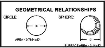
b) Plug the diameter (9 5/8 in.) into the formula for the area of a circle (area of the casing):
9.625 × 9.625 in. × 0.7854 = 72.76 in^2
2. The next step is to calculate the weight of the pipe when it is hanging in fluid (the downward force of the pipe in the wellbore.)
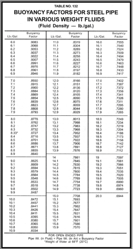
a) First, look up the buoyancy factor for the wellbore fluid you are working with. Consider that this buoyancy factor relates to an open-ended pipe weighing less in a fluid than in air. The weight of this fluid is 8.7 lb/gal. Referring to the “Displacement” section of the Red Book (see also Figure 4), you will see that the buoyancy factor is 0.8671 for a fluid of that weight.
b) You must also know how much your casing weighs in air. From the casing stamp, you can find that this casing weighs 36 lb/ft.
c) Since it is unknown at what depth the annulus might become bridged, utilize the overall length of your casing (300 ft) for these calculations.
Weight of the pipe hanging in fluid = Buoyancy factor x Weight per foot of casing x Length of the casing
0.8671 BF × 36 lb/ft × 300 ft = 9364.68 lb (downward direction)
Now you have enough information to calculate the pressure to apply to the casing at the surface, pumping downward through the casing below the casing shoe to start the lift (or to balance the pipe). The larger the diameter of the pipe, the less pressure is required to lift the string. This is why you must chain down a large diameter casing during the pumping operation (chain it to the substructure or a leg of the drilling rig derrick, but not to the rotary table).
3. Calculate the required pressure to start the lift
When applying pressure to start circulation, caution should be taken to prevent the pipe from blowing out of the hole and causing damage. The casing should be chained down, and all personnel, except the operator, should be cleared off the rig floor.
The pressure required to start the lift = The downward force of the pipe ÷ The area of the pipe
9364.68 lb ÷ 72.76 in. = 128.706 psi
6 Calculating Pressure to Land The Plug During Casing Cementing Job
Calculations for pressure to land the plug shall be made on each job. You need to get the pressure required to put the cement in place.
- Any buildup over this pressure might indicate channeling or bridging in the annulus.
- A loss of pressure could mean a loss of cement in the formation.
Due to the fluids having different weights, a differential pressure results. To calculate, you must convert the lb/gal of the cement and displacement fluid to psi/ft. We will do this with the usage of the constant 0.05195. Using multiplication, this constant will convert any fluid weight to psi/ft.
To reduce errors, here is the most accurate way to perform this calculation: Working from the bottom of the casing up to the surface, calculate the hydrostatic pressure outside, then calculate the hydrostatic pressure inside.
Reminder: All the work will be from the bottom up, for the entire casing string.
Hydrostatic Outside
Cement
300 ft × 14.8 lb/gal x 0.05195 = 230.658 psi
Total Hydrostatic Outside for 300 ft = 230.658 psi
Hydrostatic Inside
Cement
40 ft × 14.8 lb/gal x 0.05195 = 30.754 psi
Well Fluid
260 ft × 8.9 lb/gal x 0.05195 = 120.212 psi
Total Hydrostatic Inside For 300 ft = 150.966 psi
Differential Pressure
Differential Pressure = 230.658 psi – 150.966 psi = 79.692 psi
Always re-total the depth. Something is wrong if you don’t end up with the same depth.
NOTE: You must slow the pump rate to a half barrel per minute to read this on a chart or gauge because high rates create friction pressure (which can give you a false pressure reading).
When the plug has been pumped to its landing position, and 79.692 psi is readable on the gauge, it has been finished successfully. Consider that you will not be able to correctly read the pressure to land a plug on all jobs. Having cement losses into the formation or producing channels in the cement will change the pressure reading.
Release the pressure when the plug lands; this will prevent a micro-annulus. Remember that it will be required to increase pressure higher than required to land the plug to pressure test its seal. Depending on the test results, a pressure test for the casing after the plug lands will be a good idea.
Calculations for Hydrostatic Pressure at a Certain Depth
You need to be able to calculate the hydrostatic pressure at any depth. For this problem, you will resolve the hydrostatic psi at 260 ft. Will this formation support the pressure exerted by the cement column down the annulus to the given point?
In this example problem, you will have only one hydrostatic pressure to work with since you have cement from the top to the bottom of the well. That pressure is 0.7689 psi/ft, and can be resolved as follows:
14.8 lb/gal x 0.05195 = 0.7689 psi/ft
NOTE: You can also search for hydrostatic pressures for specific fluid weights in the bones section, Pages 18-21 of your Redbook.
The hydrostatic pressure in a casing job is the pressure in the annular space. The plug will shut in the pressure in the casing when it lands on a float collar. If you do not land the plug or run a float collar or back pressure valve but only stop the plug in the casing, then you will shut in the cementing head, and the pressure to land the plug will be on the casing until the cement has set.
Hydrostatic pressure at a certain depth = depth x the fluid gradient (psi/ft) of the fluid in the annulus
– in this case, cement slurry:
260 ft × 0.7689 psi/ft = 199.914 psi
7 Calculations for Resulting Force After Finishing Oil Well Casing Cementing Job
Precautions shall be considered before pumping the plug down on a surface casing. You need to discover if the casing will remain still or if the plug landing pressure will pump the casing out of the hole – if so, you will need to chain the pipe down (in addition to chaining the head to the elevators).
As you did in Calculation 5, you will calculate the difference between the upward force on the pipe and the downward force on the pipe.
1. Calculate The Upward Force
You have calculated the area of the surface casing (Step 1b – Pressure to Lift the Pipe Calculations) to be 72.76 in^2 . In addition, you know the pressure to land the plug is 79.692 psi (Pressure to Land the Plug Calculation – Differential Pressure). Multiplying the two values will give you the amount of upward force in pounds.
Upward force = Area x P required to land the plug
72.76 in^2 × 79.692 psi = 5798.39 lb
2. Calculate The Downward Force
Get the buoyancy factor from Redbook tables for the 8.7 lb/gal displacement fluid (Step 2a – Pressure to Lift the Pipe Calculations). Going to the Bone section again, search for the buoyancy factor for the cement utilized (Fig.4). The density of cement is 14.8 lb/gal. To find the buoyancy factor for this density, you must search for 14.8 lb/gal.
Now, the length and weight of the pipe in question are required. Cement is inside the pipe in the shoe joint (40 ft), and displacement fluid is inside the pipe above the float collar (260 ft). The weight of the pipe is 36 lb/gal.
Using the formula for downward force, resolve the downward force contributed by the displacement fluid:
Pounds of downward force = Length of pipe × Buoyancy factor for the displacement fluid inside the pipe × Pipe weight per foot
260 ft × 0.8671 BF × 36 lb/ft = 8116.06 lb
3. Determine the downward force contributed by the cement:
Pounds of downward force = Length of pipe × Buoyancy factor for the displacement fluid inside the pipe × Pipe weight per foot
40 ft × 0.7689 BF × 36 lb/ft = 1107.22 lb
4. Obtain The Total Downward Force
Adding these two downward forces together (Step 2 and 3) will give you the total downward force:
8116.06 lb (downward) + 1107.22 lb = 9223.28 lb ( Dowmward)
5. Calculate The Resulting Force After The Casing Cementing Job
Subtract the upward force (Step 1) from the downward force (Step 4) to get the resulting force:
9223.28 lb – 5798.39 lb = 3424.89 lb
Although this is considered a downward force, it will be mandatory to chain down the casing as a precautionary measure.
Oil Well Casing Cementing Calculations Spreadsheets
You can choose from the spreadsheets below
Download Oilfield Casing Cementing Calculations Spreadsheet # 1

Download Oilfield Casing Cementing Calculations Spreadsheet # 2

Download Oilfield Casing Cementing Calculations Spreadsheet # 3

As a Newbie, I am permanently browsing online for articles that can aid me. Thank you
You are welcome
Hello,
There is a mistake on the calculation of the cement volume on the annulus, you didn’t take on consideration the the Excess % witch is 100% means the double of volume so:
Volume of slurry In Annulus = Annulus length x Capacity (ft^3/ft) x 2
300 ft × 0.3132 ft ^3/ft x 2 = 187.91 ft^3
and all the numbers above should be changed.
Thanks
an other mistake here on calculation of the Hydrostatic Inside Cement, the well fluid density is 8.7ppg not 8.9 So:
40 ft × 14.8 lb/gal x 0.05195 = 30.754 psi
Well Fluid
260 ft × 8.7 lb/gal x 0.05195 = 117.511 psi
Total Hydrostatic Inside For 300 ft = 148.265 psi