Land Rig Move Planning
New Location Preparation
- Rig T.P shall inspect the new rig location (Check also types of drilling rigs) before moving to confirm leveling Dimensions, compaction, caller, access roads conditions & mud sump was done in a suitable way.
- NTP Make out rig layout on the new location.
- Prepare the area for drill pipe boxes.
- Cut off the conductor pipe at a suitable level above the ground.
- Check the camp location and make the footprint for caravans.
Rig Move Safety Meeting
The Safety Meeting Should Be attended by all the crews, meeting should be done every morning of rig move and supervised by drilling supervisor, STP & Safety officer
Responsibilities
- All rig equipment shall be spotted on location in accordance with the rig layout drawing
- The new location shall be marked/staked in accordance with the layout drawing by the NTP prior to the commencement of the rig move
- To assist with spotting rig equipment, the location is marked with guide ropes, A grid of perpendicular and parallel lines (guide ropes) is marked relative to well center, the grid shall be marked as accurately as possible and shall be checked (using the Pythagoras triangle 3/4/5) to ensure that all the lines are indeed at right angles and others at parallel positions
- Senior Tool Pusher overall responsibility for the old location
- Night Pusher’s overall responsibility for a new location
- The truck pusher checks each truck before leaving the location and assures proper loading, chaining, and condition of securing tools
- The mechanic, crane operator, and truck pusher inspect crane and trucks
- Truck pusher checks the overhead electric cable height before crossing with the convoy and compares it with actual height including the truck
- AFPC OSA/R will assist with the inspection of trucks and accompany the convoy as necessary
- The road Junction which has the potential to cause problems for long and wide load should be avoided and the route should be changed
Onshore Rig Move Operations
A network plan for the movement of the electrical rig is drawn showing explicitly the dependency relationships among the activities during rig building. The network would help for critical path identification with the least possible float, where additional resources like cranes, trailers, trucks, tools, human power, etc. can be ~ployed for early completion. It also furnishes planning of parallel activities. The plan highlights explicitly the dependency of various departments like mechanical, electrical, transport, auto, security, civil, drilling, chemistry, etc.
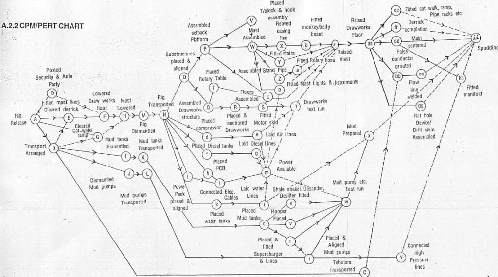
| SL no | Activity | Activity Code | Preceding Activity |
| 1 | Rig Release | A | – |
| 2 | Arranged Rig Transportation | B | A |
| 3 | Transportation of Tubulars | C | A, B |
| 4 | Posting security and Auto party | D | A |
| 5 | Fitting of mast bull lines and Derrick floor clearance | E | A, B |
| 6 | Lowering of Draw works floor | F | E |
| 7 | Clearing of Catwalk, inclined ramp, pipe rack, etc. | G | A, B |
| 8 | Lowering of Mast | H | F, G |
| 9 | Dismantling of Mud tanks | I | B |
| 10 | Dismantling of Mud pumps | J | B |
| 11 | Transportation of Mud tanks | K | I |
| 12 | Transportation of Mud pumps | L | J |
| 13 | Rig Dismantling | M | H |
| 14 | Rig Transportation | N | M |
| 15 | Alignment & Assembling of substructures. | O | N |
| 16 | Assembling of set-back platform | P | O |
| 17 | Assembling of Draw works Structure | Q | O |
| 18 | Placement of Drawworks | R | Q |
| 19 | Placement of motor skid | S | R |
| 20 | Placement of Rotary table | T | Q |
| 21 | Floors Assembling | U | P, S, T |
| 22 | Placement of Travelling Block and hook Assembly | V | P, S, T |
| 23 | Assembling of Mast | W | P, V |
| 24 | Reeving of Icasing line | X | W |
| 25 | Staircase fitting | Y | X |
| 26 | Assembling of standpipes | Z | W |
| 27 | Rotary hoses connection | a | Z |
| 28 | Assembling of monkey and belly board | b | X |
| 29 | Placement of compressor | d | N |
| 30 | Commissioning of Airlines | e | d |
| 31 | Placement of Diesel tanks | f | N |
| 32 | Commissioning Of Diesel lines | g | f |
| 33 | Placement of power control room (PCR) | h | N |
| 34 | Placement & Alignment of power packs | i | N |
| 35 | Connection of electrical cables and lines | j | h, i |
| 36 | Placement of water tanks | k | N |
| 37 | Commissioning ot water lines | l | k |
| 38 | Power made available | m | e, g, j, i |
| 39 | Drawworks test run | n | S, e, m |
| 40 | Fitting & testing of Mast light & instrumentation | p | w, m |
| 41 | Placement of Mud tanks | q | k |
| 42 | placement of supercharger & fitting of lines | r | q |
| 43 | Placement & Alignment of Mud pumps | t | L |
| 44 | Shale shaker, desander, desilter, etc. fitting | u | q |
| 45 | Placement of hopper skid | v | q |
| 46 | Test run of Mud pump etc. | w | l, m, r, t, u, v |
| 47 | Mud preparation | x | I, w |
| 48 | High-pressure lines connection | y | t |
| 49 | Mast Raising | z | U, Y, a, b |
| 50 | Raising of Draw works floor | aa | z |
| 51 | False conductor grouting | bb | C, aa |
| 52 | Welding of flowline | cc | bb |
| 53 | Mast Centering | dd | aa |
| 54 | Catwalk, inclined ramp, pipe rack, etc. fitting | ee | aa |
| 55 | Derrick completion | ff | aa |
| 56 | Rate hole device/Drill stem makes UP | gg | aa |
| 57 | Fitting of manifold | hh | y, dd |
| 58 | Spudding | ii | x, vv, dd, ee, ff, gg, hh |
Rig Move/moving with rolling gear -Old Location
- Dismantle all Mud Systems and load to a new location
- Pull and Haul Mud Pumps from the old location to the new location by Ken worth or Mack
- Secure the rig and remove all insecure tools and equipment and secure loose tools
- Raise the substructure from the rear (V – door side) with Rig – jacks and put the blocks/spacers under the sub–base tower to release the load on the jacks
- Raise the substructure from the front with the help of jacks
- Engage the Mack trucks and secure the wheel by bolts Insert Pins and release the rig ( load ) from the jacks onto the Mack trucks
- Straight pull when starting to move and no direction change until the unit is moving
- The single direction of movement/positioning of the rig over the cellar
- The minimum turning circle is 50 m
- The minimum width of the level roadway is 40 m
- Maximum speed 7 km/hr
- Inspection requirement for rolling gear every 120 km/hr as a maximum
- Move the rig to the new location
- Move the Power Engine Trailer to a new location
- Load fly camp on Trailer and move.
- Load the main camp to the new location
Rig–up (for Rig move with rolling gear )
- Rig up – new location
- Spot shaker tank first and all mud system tanks
- Spot the substructure at the well center
- Raise sub – the base again by jacks ( rear side ) and remove the metal blocks/spacer
- Release the jack and lower sub base
- Raise the sub base from the side, remove the pins
- Remove Mack trucks and lower the sub-base by releasing the jacks
- Spot power engines trailer and diesel tank
- Spot all other loads and fly camps
- Rig Up
- Fill pre – spud checklist
RIG MOVE – with dismantled mast
- Remove the Rig-move rolling gear package.
- Rig down Dog house and stand-pipe manifold and HP lines.
- Remove pins and lower setback area, using cranes.
- Rig down the Setback area.
- Rig down the Rig floor area, using cranes.
- Lowering of the rig mast -to be carried out from the Driller‘s panel near the Draw works, at ground level
Lowering of Mast
- Attach snub lines to heavy truck
- String raising lines thru sheaves in mast side frames
- Unpin lifting frames to mast side frames
- Ensure no tension on the bridle line
- Pull w/a heavy truck (5 m to start lowering the mast
- Release line from the truck – continue lowering mast le Magoo brake
- Ensure the weight indicator works correctly (increase in weight)
- Stop lowering the mast (10) mts off the ground
- Position Crown stand
- The lower mast on the crown stand
- Position the catwalk under the traveling block and chain it
- Prepare to disassemble the mast
Dismantle mast into sections as detailed below:-
- Mast Bottom Section (ODS & DS)
- Mast Middle Section (ODS & DS)
- Mast Top Section (ODS & DS)
- Crown Block
- Rig support beams (ODS & DS)
- Dismantle Setback area
- Dismantle A-frames (ODS & DS)
- Remove Draw works and Sub-base
Substructure disassembly
- Remove the raise line, fast line, deadline and D/W
- Unpin Dl/V support spreaders between draw work side frames and unpin same with rear draw works legs.
- Disconnect and remove lifting frames.
- Disconnect the mast stem with the mast side frames.
- Unpin rear and front draw work legs with bottom boxes.
- Disconnect rotary table rear spreaders with mast side frames and the same with bottom boxes and setback pad.
- Remove bolts of mast shoes and D.L anchor to mast side
- Unpin rotary beams with setback pads and setback pads with
- Setback legs.
- Disconnect setback legs with bottom boxes
Substructure assembly
- The substructure and mast are both assembled in the down position
- Level the site
- Set bottom boxes and connect spreaders
- Pin setback legs to bottom boxes
- Pin setback pad to set back legs, pin rotary beams to set back pad set rotary table
- Bolt mast shoes and deadline anchor to mast side frames
- Pin mast side frames to bottom boxes and set back pad pin rear rotary spreader to mast side frames
- Pin rear draw works legs to bottom boxes. Pin front draw works legs to bottom boxes
- Pin rear draw works legs to bottom boxes. Pin front draw works legs to bottom boxes
- Pin mast stem to mast side frames, use mast headrest to support mast during assembly
- String raising lines through sheaves in mast side frames; leave another end on the set back pad
- Pin lifting frames to mast side frames and lay forward
- Attach bull line thru sheaves on lifting frames, pull towards draw works rear legs, string line thru sheaves on bottom boxes and pull back to lifting frames, and anchor to plates
- Pin draw works side frames to front and rear drawworks legs
- Pin drawworks support spreaders between drawworks side frames
- Set drawworks and accessories, string fast line over fast line roller and pull to fast line sheaves on the crown, string – up block, attach a deadline to deadline anchor
Raising Mast
Preparation
- Check the Mast, to ensure that all the pins are in place.
- Start two Generators, put them online and keep all the SCR online
- Have substructure heel subs installed and pinned?
- Install stabbing board. :
- Ensure sufficient wraps on Drawworks drum.
- Check the Deadline anchor.
- Check the DA/V drum drill, and line anchor.
- Inspect drawworks brakes and lineage.
- Ensure drawworks are pinned to substructure heel sub.
- Ensure the hook is locked.
- Inspect bridle lines and pins
- Install and tie up all rig derrick wire lines.
- Secure the derrick or rig mast lighting lamp cables.
- Ensure that Eddy’s current brake is working (clutch engaged, power is on, and cooling water circulating).
- Install the bridle line in the hook.
- Shift drawworks transmission to low-low.
- Grease and check all sheaves for free rotation.
- Ensure that no loose tools are left in the derrick.
- Attach the snub line to the mast and hook another end to a heavy truck /forklift, as a counterbalance.
- Perform final inspection.
Mast raising Procedure
- Rotate in DW drum and take 85,000 lbs ten minutes, to check that everything is OK
- Raise the derrick off the crown stand.
- Install monkey board.
- Raise the mast to its vertical position and Pin the mast side frame to the bottom boxes. Pin rotary beams.
- Disconnect the bull line from the lifting frame.
- Install floorings, handrails, ramp, and stairs.
- Hook up dog house support and dog house
Precautions To Be Taken While Rig Building
Inspection Of Mast And Substructure
- While the mast and substructure is a relatively minor items in the total cost of the drilling rig (check also drilling cost per foot), their failure could result in a major disaster. Damage to the equipment and possible personal injury, make a mast and sub-structure operation of prime importance. Failure is usually caused by some prior damage thought to be minor as not to warrant a repair job.
- Every care should be taken during the dismantling and moving of the rig to a new location. Most of the bending of the mast and substructure components (Rig components) is caused by rough and improper handling during their transportation and local movement.
- Follow strictly procedures recommended in the manual for handling, raising, and lowering the mast and sub-structure, provided by the manufacturer along with the rig.
- No overload beyond the specified capacity is permitted.
- During drilling operations, it is advised to make a frequent inspection of bolted connections to ensure none has worked loose.
- All the mast shoes shall be in the same plane. When the sub-structure is not level, the traveling block will not hang true over the well. To correct this situation, the centering of the block shall be done with the help of shims.
- It is recommended that lubrication of crown block sheaves be done at least once a week. The lubrication is to be done by pressure lubrication through an individual passage drilled into crown shafts.
- Grease and lubricate mast shoe pins before fixing through A-Frame, to facilitate the smooth mast raising.
- Before assembling in a new location, parts that were wet with drilling mud or have lost the paint, etc. shall be thoroughly cleaned and repainted.
- The mast should be inspected for bend members or cracked welds before being raised or lowered and before handling heavy strings of pipe.
- Members bent, damaged, or twisted during handling shOuld be replaced/repaired before being raised.
- Sling lines should be maintained in well-lubricated conditions to reduce corrosion.
- Wire ropes including operating lines, raising lines, and guy lines should be inspected for kinks, broken wires, or other damage before use. In case they are found to have kinks or broken wires, shall be replaced.
- Make sure that each reeving line is in place in the sheave-groove before each raising or lowering operation.
- Sheave guards are provided which prevent the line from jumping off a sheave. These should always be intact.
- Cutting of bolts or dropping of members is strictly prohibited.
- Bolt holes should not be enlarged or distorted.
- All structural bolts should be fixed with suitable lock washers. Inspection should be carried out to thoroughly check the proper tightening and placement of the right bolts with spring washers, after assembling.
- Ensure that the holding bolts with the pins are intact.
Precautions During Raising & Lowering Mast
- Inspect all the welded joints of lugs for cracks, corrosion, and pittings.
- Inspect for free rotation of all mast lifting sheaves.
- Inspect the casing line and bull lines for clinks, breakage, brittleness, and corrosion.
- Inspect the reeving pattern of the casing line and bull line.
- Inspect the anchor points of bull lines on the mast and spelter sockets of the rope.
- Inspect the fast line and deadline fixtures.
- Inspect all the sheaves of the crown block for free rotation.
- Inspect the foundation bolts of the draw works for their proper tightening.
- Inspect for missing pins and members.
- Inspect all lock pins.
- Inspect for any damage to the mast members. It is to be seen during the assembling
- Check the effectiveness of the mechanical brake. hydraulic brake and electromagnetic brake of draw works.
- Check for all loose tools left in the mast during Assembling.
- Inspect the A-frame pulley assembly, pins of the A-frame, and all weldments of the frame.
- Check the equalizer pulley unit/pins/welds/bearing surfaces.
- Check traveling block and hook assembly. For hoisting and lowering of masts of different types. Follow the operating instructions in the manual supplied by the manufacturers.
Mast Centering
- Align the mast before drilling using a traveling block with a suspended drill collar as a bob.
- Jacking and lowering should be done on one leg at a time with a hydraulic jack.
- Provide adequate shims, if required
- No bolts should be removed from shoes, only loosen the nuts. After mast centering retighten the nuts.
Preservation
- Wherever parts/items have lost paint due to rubbing, working, or cutting for rectifications during rig up shall be repaired as follows:
- Mast and sub-structure members-white epoxy paint.
- Mast support stand -red lead paint.
- Flooring and grating -gray -synthetic enamel paints.
- Sub-base beam -black synthetic enamel paint.
- Crown frame -yellow epoxy.
- Sheaves -red or enamel paint.
- All other parts -white epoxy paint.
- All pins shall be cleaned and applied with temporary corrosion preventive grease (IS: 958 -58).
- All nuts and bolts shall be applied temporary corrosion preventive grease (IS: 958 -58) along with their threaded length.
- The sling lines with sockets should be cleaned and applied with temporary corrosion preventive grease.
- The sheaves and bearings are to be lubricated as per instructions specified in the manual.
- The groove portions of the sheaves should be cleared & applied with temporary corrosion preventive lacquer as per company standard No. C50022102 of BHEL.
- Fast line floating shaft, in the A-frame spreader & strong back beam, shall be applied with corrosion preventive lacquer as per company standard No. CS 0022102 of BHEL.
- All sub-structure and mast shafts shall be applied with corrosion preventive lacquer, wherever exposed.
Note:
The report should be filled accordingly as given in API SPEC 4E under the head “Report of visual field inspection of derrick or mast and substructure”.
Jack-up Rig Move Steps
The planning and sequence of operations have been divided into the following 12 steps:
- Determination of Jackup Rig location
- Perform soil and seabed survey
- Geotechnical investigation
- Preparing site-specific procedures
- Preparing any certificates or legal permissions
- Onboard review of the site-specific procedures
- Preload simulation
- Onshore pre-move meeting
- Preparing for the rig move
- Rig move
- Preloading and final accepting
Notes
- Soil & Seabed survey: Especially in areas with special soil conditions which could lead to rapid penetration and/or punch-through
- Geotechnical investigation: This data will help in a foundation assessment being issued, giving estimated penetrations and ascertaining any risk of rapid penetration and/or punch-through.
- Onboard review of the site-specific procedures: When the draft procedures have been completed by the Seadrill Regional Office, they have to be forwarded to the Rig Manager, OIM, Marine Section Leader, Rig Mover and, if deemed necessary, the MWS, for review and comments.
- Preload simulation: It is useful to be done based on the procedure and actual/ estimated deck load.
- Onshore pre-move meeting: Pre-move meeting at which each procedure shall be reviewed and agreed upon. Minutes of this meeting form part of the post-rig move report.
Jack-up Rig Move Planning
Rig Crew
The minimum core crew recommended onboard a Jack-up during a field move or ocean tow should consist of the following:
- 1 OIM
- 2 (two) Marine Section Leaders depending on the duration of preloading operations.
- 1 Maintenance supervisor
- 2 (two) Electricians
- 2 (two) Mechanics
- 2 (two) Motorman
- 2 two) Radio Operators
- 1 (one) Cook
- 2 (two) Stewards
- 2 (two) Crane Operators
- 1 (one) Welder (optional)
- 3 (three) Seaman-skilled persons
Supply Vessel
- The AHTSV and its equipment shall be inspected and approved prior to the commencement of the towing or any anchor handling operation.
- The minimum required bollard pull, as specified for the individual Jack-up, shall be stated in the rig move procedure
The inspection shall as a minimum include the following items:
- Bollard pull/ BHP meets the minimum requirements for the particular unit
- Towing and work winches – primary and secondary
- Auxiliary winches
- Stern rollers and mechanic stoppers (E.g. Shark Jaws / Karm Forks)
- Main and spare towing wires
- Work wires, shackles, connecting links, and any other equipment planned to be utilized during intended work scopes
- Crew list including a position on board and qualification notes
- All vessels shall be suitably manned in accordance with legislation and work scope and shall be capable of operating on a 24 hours continuously basis if required within the work scope
Weather
The establishment of good quality weather forecasting, which should be both site and route-specific, is essential for identifying the weather window required and for the safe conduct of the operation.
It is advisable to commence the forecasting timely thus having a possibility of evaluating the development of weather patterns etc. and making the necessary comparison between the forecasted and actual weather. The decision to commence a rig move shall be based on a suitable window.
Note:
- Check your company standards for Weather Window
- Check how to measure sea conditions,
Jack-up Rig Move Operations
Drilling units/rigs are designed to move from one location to another location for undertaking drilling/workover operations after completing operations at an earlier location. As soon as the rig is released from the location, it has to be prepared for the move to a new location. The following are the steps involved:
- The cantilever and substructure are to be skidded into towing position
- Drilling string, casings, etc. are to be placed on a pipe rack and secured
- Hook, traveling block, etc. to be tied Up
- The lacing of all the loose material
- Securing all water-tight doors/hatches etc.
- All the openings or dumps must be fully closed
- Backload the material to bring variable load within permissible limits.
The following checks are to be carried out:
- Gather information about prevailing wind, waves & currents.
- Check and obtain the weather forecasts for 72 hours.
- Checking all towing gears.
- Check all safety aids for navigation, life-saving communication equipment, and lighting.
- Torque equalization of all the jack-up motors.
After taking the above steps rig is ready to be jacked down. Furthermore, before jacking down and moving off the location following information must also be available:
- Coordinates and name of next location.
- Distance of new location from departing location.
- Names and capacity of towing boats duly inspected and approved by warranty surveyor.
- Soil data of new location expected leg penetration and punch-through possibilities.
- Report of seabed survey of the new location to ascertain that no significant debris/pipeline is present within a 100 x 100 m area in the north face of the platform (platform rigs) and in a radius of 100 m of open location.
Jacking Down Operations
The rigs are accepted for jacking down subject to the following:
- All the materials are properly laced and tied up.
- The variable load is within permissible limits.
- The cantilever and substructure are stowed in and locked properly.
- All the watertight doors and other openings are properly closed.
- The stability calculations are ready for floating conditions.
- The load equalization and torquing of jacking motors are completed.
- Three officers are to be made leg in charge to have communication with the control room.
- Nine people are required for the greasing of rack teeth, leg chords, etc. (three for each leg).
- Boats are to be tied up at 5m (approx) air gap.
- Water-tight integrity should be checked at 3 m draft or as per operation manual instructions.
- In case water-tight integrity is doubtful the hull is raised again and repair action Is taken.
- If water-tight integrity is O.K, the next operation is releasing of legs.
Releasing of legs
- The hull is lowered to a floating draft.
- Legs are released by increasing the floating draft (not exceeding 1 meter) or as per instruction in the operation manual.
- One person should be stationed at the side of the rig to ensure that the rig does not come very near to the platform.
- If legs do not get released by increasing draft, the jetting lines should be hooked up and legs should be released by jetting.
- Once all the legs are released, the legs should be raised to 3 to 5 m above the sea bed before the rig actually starts off the location.
Lowering of legs
- When the rig is within 1 to 1/2 mile from the new location, start lowering of legs.
- The legs are kept clear of the sea bed while the approach is made toward the location.
- The approach to the location is to be done in a slack period and in permissible weather.
- Before approaching the location the sea bed survey report should be available.
Docking at location
- The docking should be done within calm and within permissible limits.
- Docking is a continuous process and all this time twelve personnel should be available for leg watching and greasing of the jacking system, rack teeth, and chord.
- The pipelines if any felt critical are to be buoyed with marker buoys to prevent damage during docking or approach of the rig.
- The rig is to be docked in such a manner that it is able to cover all the slots.
- Once the rig is docked and the location is confirmed it is required to be raised to a minimum air gap (2m in case of proven location and 1 m for critical and new locations) to release boats and carry out preloading.
Preloading
- Preload calculations should be ready beforehand.
- Preloading is to be carried out at a minimum air gap. The preloading can be done on all three legs simultaneously or sequentially one by one depending on soil data information and the nature of the location.
- Preload is to be held normally for one hour or as per the recommendation of the warranty surveyor.
- During preloading an adequate number of people should be available near dump valves to attend dump valve opening in case dumping is required to meet the eventuality caused by punch-through or rapid penetration.
- Preload is to be dumped after completing preloading and holding of preload as per requirement.
- After completing preloading, the load on each motor should be equalized and the motor should be torqued.
- Raise the hull to a 6 m air gap and release the boats. Jacking up to the required air gap is the most critical stage of the jacking operation. Twelve people (three leg supervisors and nine greasing personnel) are required continuously near the legs, as during this operation maximum load at the barge is encountered by the jacking system.
Thanks
This is a good overview of Rig move.
I just finished the Alqaher 1 offshore rig moving on board of AHTSV INW 30 as a master leading the rig to new location. But some terms I heard not familiar with so now after I got your site I understood most of orders which tow master give it to his crew on the rig.Thanks so mutch,kind regards.
This is a valuable template to generate a plan specific to your Rig.