A clear collar response can still leave a workover tool at the wrong depth. The response must belong to the intended collar on an accepted reference, and the tool’s working point may be several metres away from the sensor. A casing collar locator supports depth correlation; the completed calculation must carry that reference to the particular point that will perform the work. [1, pp. 1-2 and 1-4]
This article follows that connection from the reference log to an illustrative tool position. It explains what the evidence can establish, how a repeated pattern can remain ambiguous, and why a signed sensor-to-tool distance matters. The numerical example is invented teaching arithmetic, with its datum, units and direction stated explicitly. For the wider choice of intervention equipment, see the guide to workover operations.

What does a casing collar locator tell you?
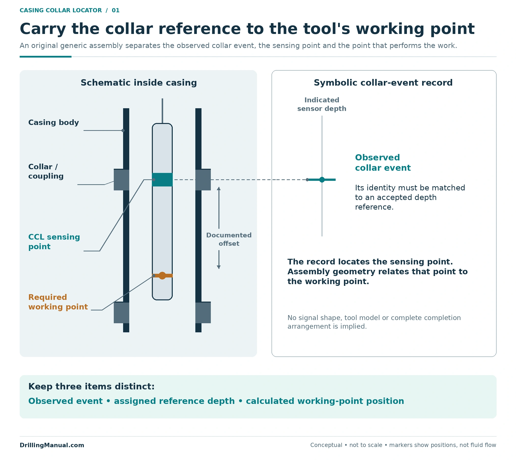
A magnetic casing collar locator, usually abbreviated CCL, provides a record associated with collars in the tubular string. Its value comes from relating those recognizable locations to an existing depth reference. Schlumberger describes combining collar information with gamma ray or neutron logs to connect casing collars with the formations identified by earlier logging. This gives subsequent wireline work a reference that can be recognized again inside casing. [1, p. 1-2]
Three things therefore need separate names: the response observed on the current pass, the reference depth assigned to the matched collar, and the position of the work-performing part of the assembly. Treating all three as “the tool depth” hides the relationship that needs checking. A collar response is information from the locator’s sensing point; it does not put every component of a combined string at that same depth. Schlumberger’s description of separate sensors and combined toolstrings makes this distinction particularly relevant. [1, pp. 1-3 to 1-4 and 4-1]
A composite log may display CCL alongside formation or production measurements. Those tracks retain different purposes. The book’s example presentation lists gamma ray and CCL separately from porosity and other formation outputs, while its production-logging discussion identifies CCL and gamma ray as correlation and depth-control measurements. A collar mark therefore helps locate other information without becoming a measurement of that information itself. [1, pp. 3-22 and 4-1]
Establish the reference before comparing the pass
The starting document needs an identity, a depth basis and a reason to trust its relationship to the intended target. An old trace without its well identification, reference datum or connection to the relevant interval is not a complete reference package. The underlying principle is straightforward: NOV CTES describes correlating surface-measured depth with a location already known in the wellbore. Choosing which record supplies that known location is part of the interpretation. [2, p. 5-25]
For a formation-related objective, establish how the reference collars were tied to the formation record. For a hardware-related objective, establish the relevant installed configuration and which tubular string the comparison concerns. A target described relative to a casing collar and one described relative to a completion component require the appropriate relationship between their records. The CCL–formation tie described by Schlumberger should not be silently replaced by an assumed identity between unrelated depth lists. [1, p. 1-2]
| Reference item | Question it resolves | Problem if omitted |
|---|---|---|
| Well, string and record identity | Which installed interval does this evidence describe? | A convincing pattern can be assigned to the wrong reference. |
| Datum, units and depth type | What does each depth number mean? | Numbers with different origins or definitions can be compared directly. |
| Connection to the target | How is the collar record related to the intended formation or hardware? | Collar identification can remain disconnected from the job objective. |
| Reference interval and supporting features | What evidence distinguishes this match from another candidate? | A short repeating sequence can appear more conclusive than it is. |
This table is an original review framework drawn from the known-location correlation principle. It is not a prescribed logging sequence. Surface depth measurement and downhole correlation also remain distinct parts of the record: Schlumberger describes calibrated measuring-wheel depth acquisition and the role of a taut cable in depth control, rather than presenting an unexplained surface number as sufficient evidence by itself. [1, p. 1-4] [2, p. 5-25]

How to correlate a casing collar locator log
Casing collar locator correlation asks whether the current observations represent the same sequence of physical features as the reference. It is more useful to examine the order and separation of several responses than to assign an identity to one isolated event. The electronic collar-location discussion in the CTES manual explicitly describes multiple collar correlations. The pattern examples here are original illustrations of that principle, not reproductions of recorded well signals. [2, p. 5-25]
A recognizable interval is stronger than a count
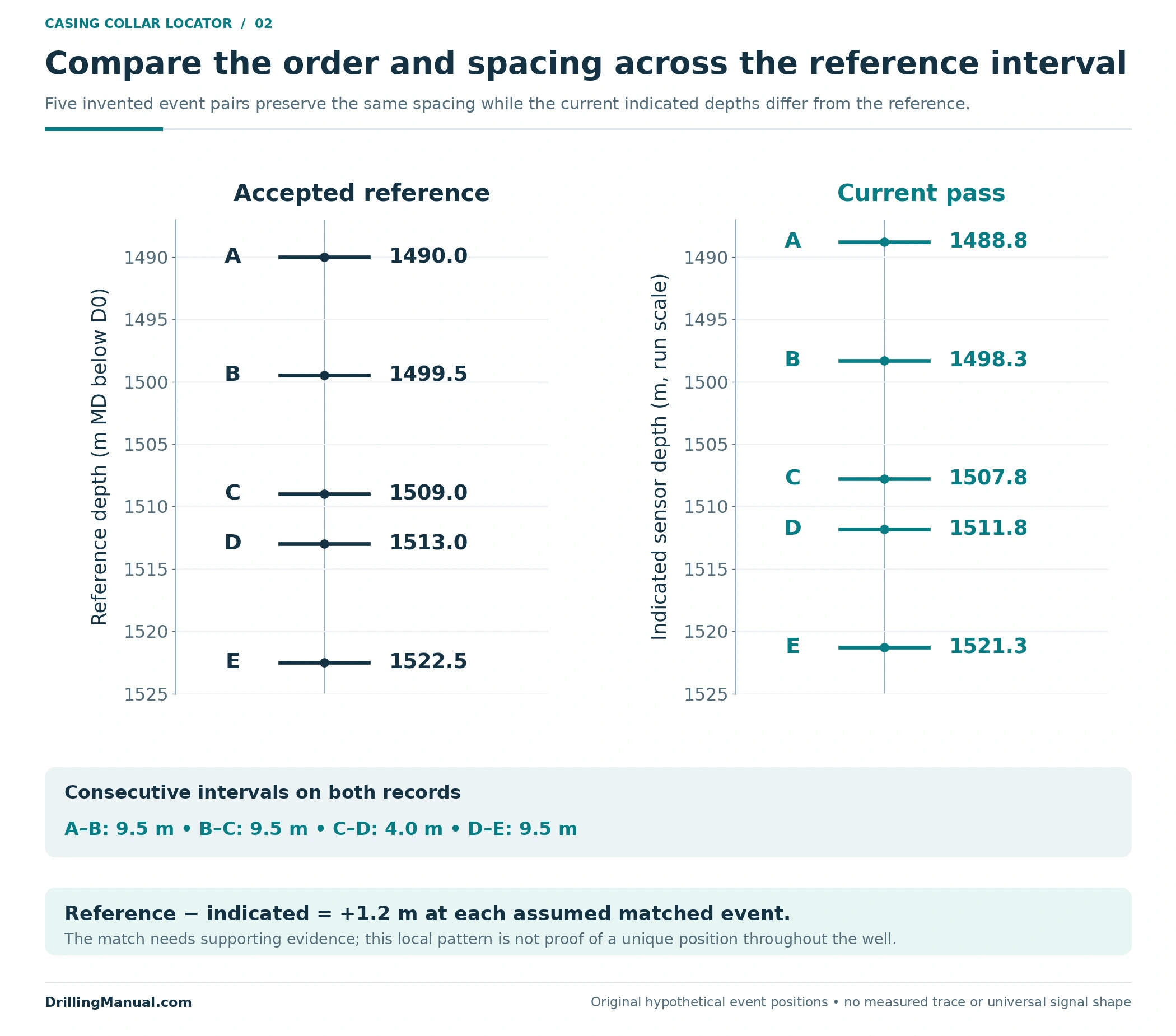
Suppose a reference contains three longer collar intervals with a shorter interval between two of them. The shorter separation adds information to the order of events. If the current pass reproduces that arrangement, the interpretation has more to explain than “five marks were seen.” The interpretation should still account for the surrounding reference and its connection to the target. A distinctive feature inside the displayed window is not proof that the same pattern occurs nowhere else in the well.
Figure 2 uses five invented event positions. The intervals are 9.5, 9.5, 4.0 and 9.5 m on both records, although the indicated depths differ. This makes the proposed alignment internally consistent within the example. No particular joint standard or universal collar waveform is implied. The reference contains a shorter collar interval; identifying its physical cause would require the applicable installation record.
An uncertain match stays uncertain
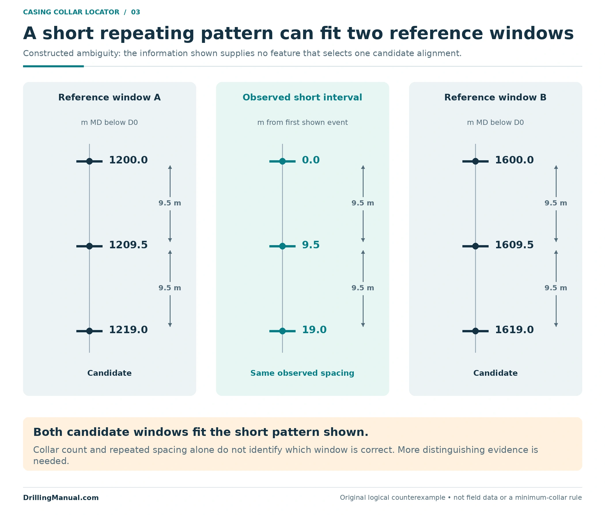
Consider two candidate reference windows that each contain three collars separated by the same distances. The same short current sequence can fit both. Counting three collars does not choose between those candidates, because the count and spacings supply no distinguishing information in that constructed example. An additional tie, a larger recognizable interval or another appropriate source of depth evidence is needed to resolve the identity. Gamma ray or neutron correlation provides the formation connection discussed in the primary book. [1, p. 1-2]
A casing collar locator interpretation should preserve ambiguity when the observations do not resolve it. An uncertain event should remain marked as uncertain; assigning it a convenient collar number does not add evidence. Likewise, a pattern that requires different unexplained depth adjustments at successive events does not support the simple constant-shift model used below. The required confidence and acceptance criteria belong to the actual job, not to a universal number of peaks in a teaching diagram.
Casing collar locator depth versus tool depth
After casing collar locator correlation, identify the point whose position has been established. Then relate that point to the assembly’s required working point. Combined strings contain sensors at different locations, and the component arrangement must be taken from the actual assembly record. The calculation should name both endpoints of the distance; “tool length” is insufficient if one person means overall length and another means the spacing from the CCL sensing point to a particular working point. [1, pp. 1-4 and 4-1]
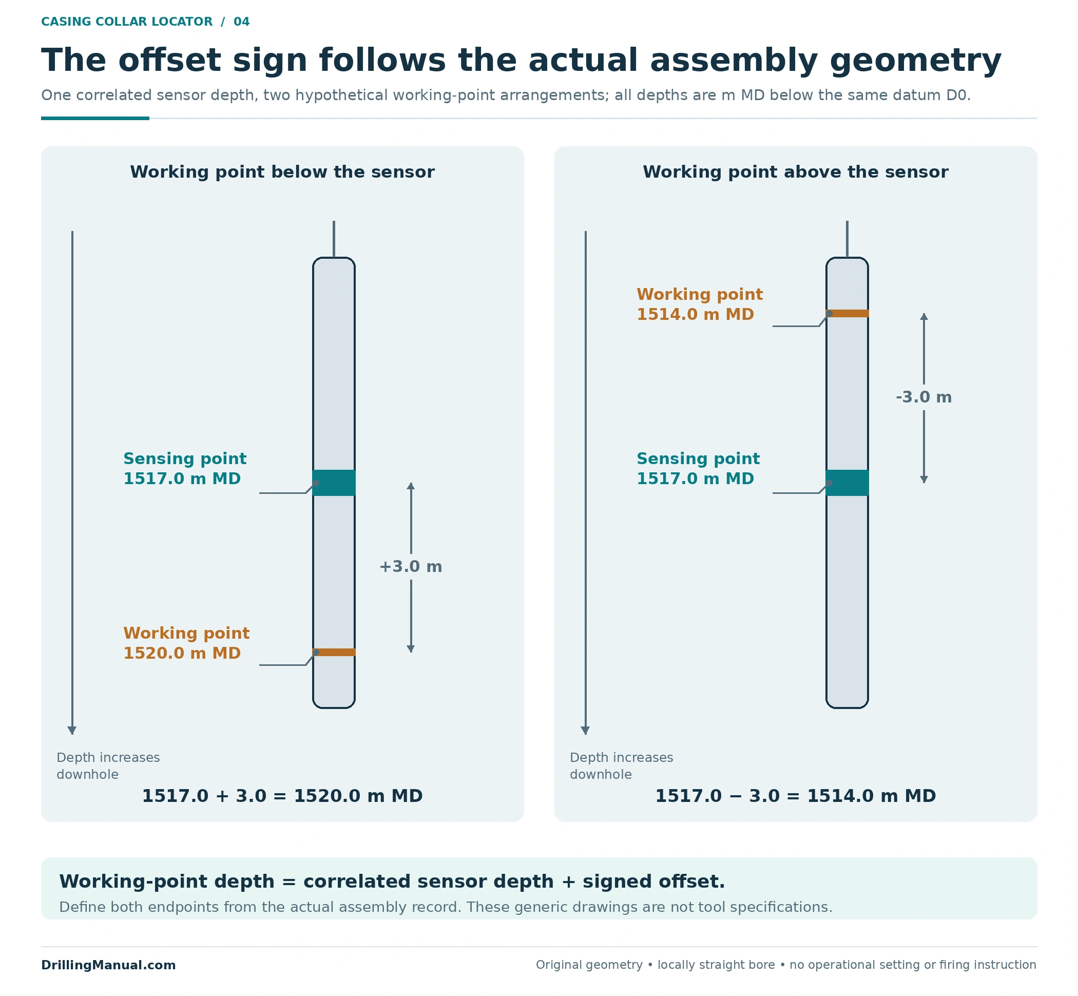
For the original geometry used here, depth increases downhole and distances follow a locally straight wellbore. A working point below the sensor has a positive offset. A working point above it has a negative offset. With those definitions, working-point depth equals correlated sensor depth plus the signed offset. This is a geometric relationship, not a model-specific operating instruction or an assertion that every tool has the same arrangement.
If the correlated sensing point is at 1517.0 m MD and the working point is 3.0 m below it, that working point is at 1520.0 m MD. If the working point is instead 3.0 m above the sensing point, its depth is 1514.0 m MD. The sign comes from the actual geometry. A different spacer, attachment or chosen working point requires the relationship to be checked again.
Worked casing collar locator depth example
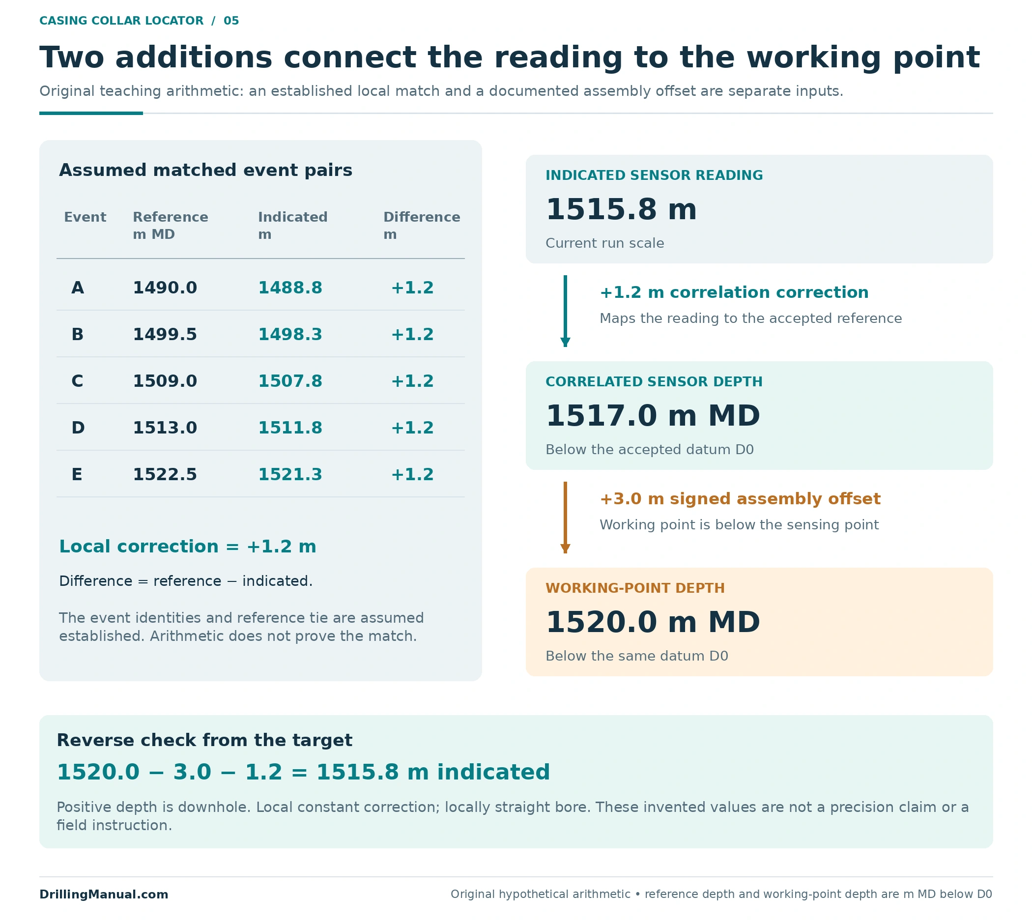
Assume an accepted reference is tied to the intended interval and that the following five event pairs have been identified from adequate supporting evidence. All reference depths are metres of measured depth, or m MD, below one named datum, D0. Positive depth runs downhole. Current readings use the same intended datum but remain indicated sensor depths on the run scale until the example correction is applied. The assembly is aligned with the locally straight bore.
First reconcile the collar positions
| Matched event | Reference collar depth m MD below D0 | Indicated sensor depth m, run scale | Reference minus indicated m |
|---|---|---|---|
| A | 1490.0 | 1488.8 | +1.2 |
| B | 1499.5 | 1498.3 | +1.2 |
| C | 1509.0 | 1507.8 | +1.2 |
| D | 1513.0 | 1511.8 | +1.2 |
| E | 1522.5 | 1521.3 | +1.2 |
Each pair gives the same difference, so the constructed data support a local correction of +1.2 m. The stated relationship is therefore: correlated sensor depth = indicated sensor depth + 1.2 m. Adding the correction makes the assigned depth deeper. This sign is written into the example rather than left to an unexplained “plus or minus” adjustment.
The identical differences are deliberate. They do not establish the cause of a real depth discrepancy, prove a global correction over the whole well, or supply a cable-stretch model. The assumed event identities come first; the arithmetic cannot turn an incorrect match into a correct one. Decimal places are chosen to make the example easy to audit and are not a claim about instrument accuracy. The book basis is correlation with a known location; these numbers and calculations are original. [2, p. 5-25]
Then locate the working point
The hypothetical objective is a working-point depth of 1520.0 m MD below D0. Its documented position is 3.0 m below the sensor. Consequently, the corresponding correlated sensor depth is 1520.0 − 3.0 = 1517.0 m MD. The indicated sensor value on this example’s run scale is then 1517.0 − 1.2 = 1515.8 m.
Independent arithmetic check: 1515.8 m indicated + 1.2 m correlation correction + 3.0 m sensor-to-working-point offset = 1520.0 m MD below D0.
The two additions serve different purposes. The first maps the indicated sensor reading onto the accepted reference. The second maps the sensor’s location onto another point on the assembly. If the sensor itself were assigned the target depth of 1520.0 m MD, the lower working point would be at 1523.0 m MD in this geometry. A correct collar match would not remove that three-metre positioning error.
Keep datum, depth type and direction consistent
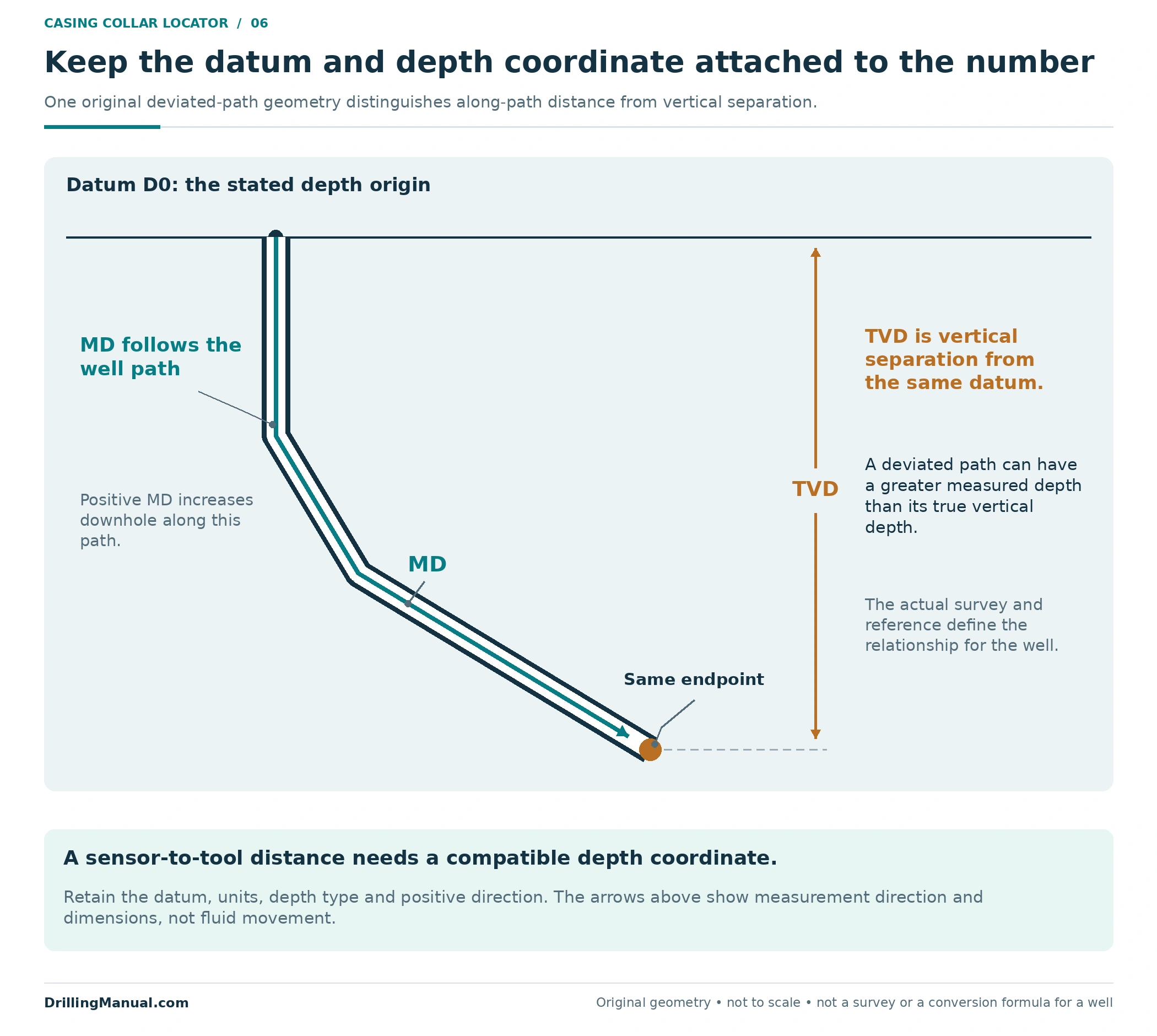
Measured depth follows the well path; true vertical depth describes vertical separation from a defined origin. Those quantities need not be equal in a deviated well. A tool-to-sensor distance measured along the assembly must be used with a compatible depth coordinate. Figure 6 is an original geometry illustration of this distinction, not a deviation survey or a conversion formula for a particular well.
The datum also belongs to the number. A depth copied from a reference with one origin cannot be treated as though it already used another. Schlumberger’s survey discussion explicitly distinguishes the origin coordinates, corrected depth and true vertical depth in the resulting record. Its particular survey system is not prescribed here; the relevant lesson is to retain the definition of the coordinate being compared. [1, p. 10-4]
In the numerical example, D0 stays unchanged throughout. The +1.2 m correction is a stated relationship between the indicated and reference scales, while +3.0 m is an assembly distance. Neither is an unstated datum conversion. Keeping those labels attached to the numbers makes an independent calculation possible and prevents the same adjustment from being applied twice.
Depth evidence supports a defined workover objective
The required working point depends on the job. Depth correlation can support the placement of perforating equipment, sealing devices and other intervention assemblies. Schlumberger discusses both perforating and wireline sealing applications, while NOV CTES includes plug, packer and tubular-cutting work in its explanation of why known-location correlation matters. These are application categories, not interchangeable tool arrangements. [1, pp. 1-2 and 10-7] [2, p. 5-25]
For related equipment background, see wireline-conveyed perforating and the guide to bridge plug types and selection. DeGeare also describes locating a collar in a sidetrack-positioning context, illustrating why the relationship between a planned working location and a connection can matter. The book’s particular clearance and orientation recommendations are not generalized into this article. [3, p. 122]
Location evidence has a defined scope. It does not by itself demonstrate a plug’s seal, confirm a completed cut or identify which interval is contributing fluid. The primary source separates correlation sensors from the instruments used to evaluate production and other well behaviour. Those functions require their own evidence. The well integrity guide provides the broader context for documenting required containment functions. [1, p. 4-1]

Review the casing collar locator evidence as a package
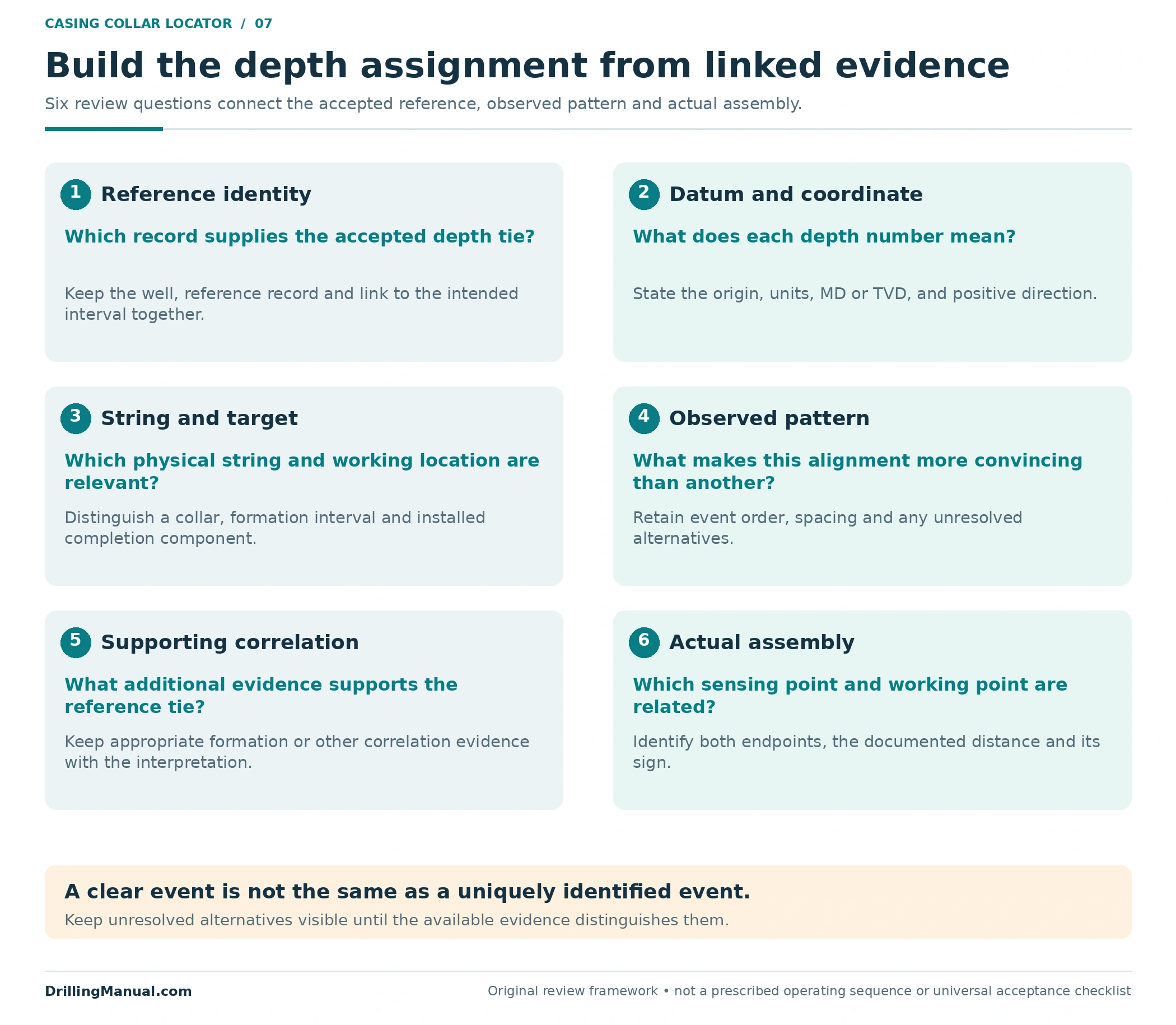
A useful review connects the reference, current pass and actual assembly. It identifies the relevant string, the target definition, the features supporting the match and the distance to the working point. It also states what remains unresolved. This is an editorial synthesis of the book’s correlation and combined-tool principles, rather than a new operating procedure. [1, pp. 1-2 and 1-4] [2, p. 5-25]
A casing collar locator worksheet also needs configuration control when the assembly changes. A depth worksheet prepared for one arrangement should not silently follow another arrangement with a different offset. The same applies when the intended point changes from the end of a tool to a component within it. The geometry must describe the object that is actually being positioned, including any relevant change associated with the selected fishing or intervention tools.
Preserve the accepted depth basis in the record
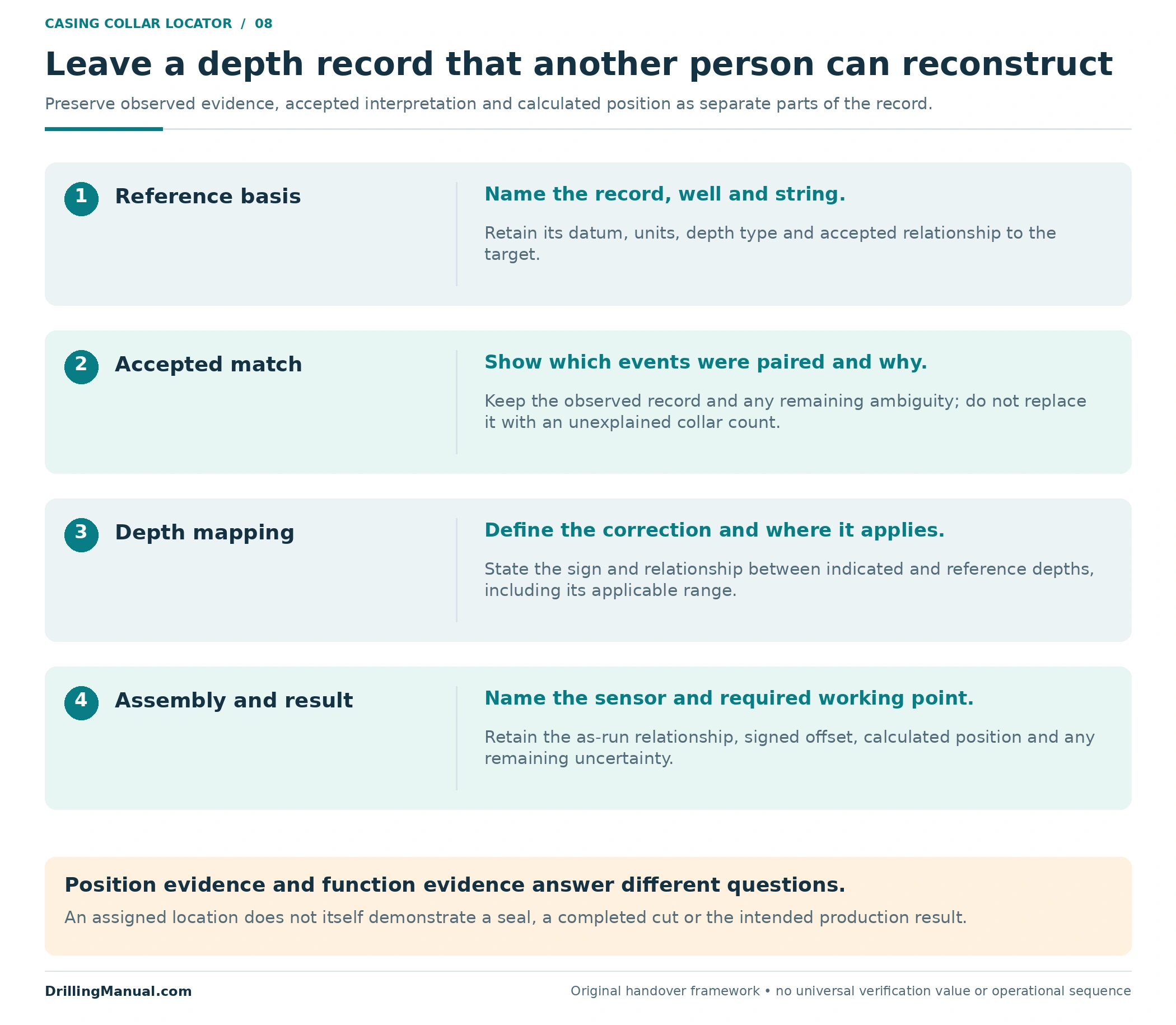
A casing collar locator depth record is useful when another person can reconstruct the reasoning. Retain the reference identity, datum and units; the accepted event matches; the relationship between indicated and reference depths; and the signed distance to the working point. Distinguish the observed trace from interpreted matches and calculated positions. Schlumberger describes preserving acquired logging data for later processing; the handover framework here extends that idea to the calculation being communicated. [1, p. 1-4]
The final statement should name the working point and the evidence supporting its assigned position, together with any remaining uncertainty. A recorded position and evidence that the work achieved its purpose are separate outputs. Keeping both visible prevents “at depth” from becoming an unsupported claim that the intended intervention function has also been demonstrated.
Casing collar locator questions
Does a casing collar locator give absolute depth?
Its collar responses support correlation to a known reference. The useful result depends on identifying the correct reference features and retaining the datum and depth definition. The surface indication, accepted collar depth and tool working-point depth should remain distinguishable. [1, pp. 1-2 and 1-4] [2, p. 5-25]
Why combine CCL with gamma ray?
They provide complementary information. Schlumberger describes using gamma ray or neutron logging with magnetic collar location to tie collars to formations. The collar record can then support depth correlation on subsequent work. A CCL event alone does not identify a geological boundary. [1, p. 1-2]
Can collar counting identify the intended location?
A count can form part of a reference-based interpretation, but it does not resolve repeating or ambiguous patterns by itself. The constructed two-window example shows why: the same count and spacing fit two different positions. Additional distinguishing evidence is needed before choosing one.
Does a strong casing collar locator signal prove the right collar?
No. Recognizing an event and assigning its identity are different questions. The accepted match must relate that event to the correct reference interval. This article does not supply a universal signal-amplitude threshold or a minimum number of collars that guarantees identification.
Which point on the assembly should match the target?
The point defined by the work objective, using its documented relationship to the sensing point. With positive depth downhole, a working point below the sensor has a positive offset in the illustrated geometry. A point above it has a negative offset. The actual assembly determines that relationship.
Can a casing collar locator prove plug isolation?
No. Correlation can support the assigned placement depth, but hydraulic isolation is a different function. A depth response does not measure that seal. The verification evidence must address the particular function being claimed, just as production measurements and depth-correlation measurements have different purposes. [1, pp. 4-1 and 10-7]
References
- Schlumberger. Cased Hole Log Interpretation: Principles/Applications. Copyright 1989; inspected copy, fourth printing, March 1997. Printed pp. 1-2, 1-3 to 1-4, 3-22, 4-1, 10-4 and 10-7; physical PDF pp. 13–15, 43, 68, 173 and 176. These sections support correlation, combined sensors, depth acquisition, coordinate definitions and positioning applications.
- NOV CTES. Coiled Tubing Manual. Inspected revision 27 June 2014; copyright 2007–2013. Printed p. 5-25, “Wireless CT Collar Locator”; physical PDF p. 157. Used for the known-location and multiple-correlation principles, without adopting historical product specifications.
- DeGeare, Joe. The Guide to Oilwell Fishing Operations: Tools, Techniques, and Rules of Thumb. Second edition. Gulf Professional Publishing, an imprint of Elsevier, 2015. Printed p. 122; physical PDF p. 117. Used for the collar-location application in sidetrack positioning, without generalizing its job-specific distances or procedure.