Paraffin removal in oil wells starts with identifying the material, locating it and defining what must be restored. Declining production warrants investigation; the rate trend alone cannot locate a suspected wax deposit. A restricted tool route provides a different observation. Neither finding alone selects a thermal, chemical or mechanical treatment. The NOV CTES manual treats deposit properties, completion geometry and reservoir conditions as separate inputs to removal planning. [1, physical pp. 400–402; printed pp. 11-103–11-105]
Wax can reduce the available flow area and interfere with downhole equipment. However, paraffin is also listed among the causes of near-wellbore formation impairment. These are different locations with different access requirements. This article examines the evidence connecting a suspected organic deposit to an achievable cleanout objective, including the reasons that an apparent improvement may leave part of the problem unresolved. [1, physical p. 400] [2, physical/visible p. 230]
Paraffin Removal in Oil Wells Begins with Location
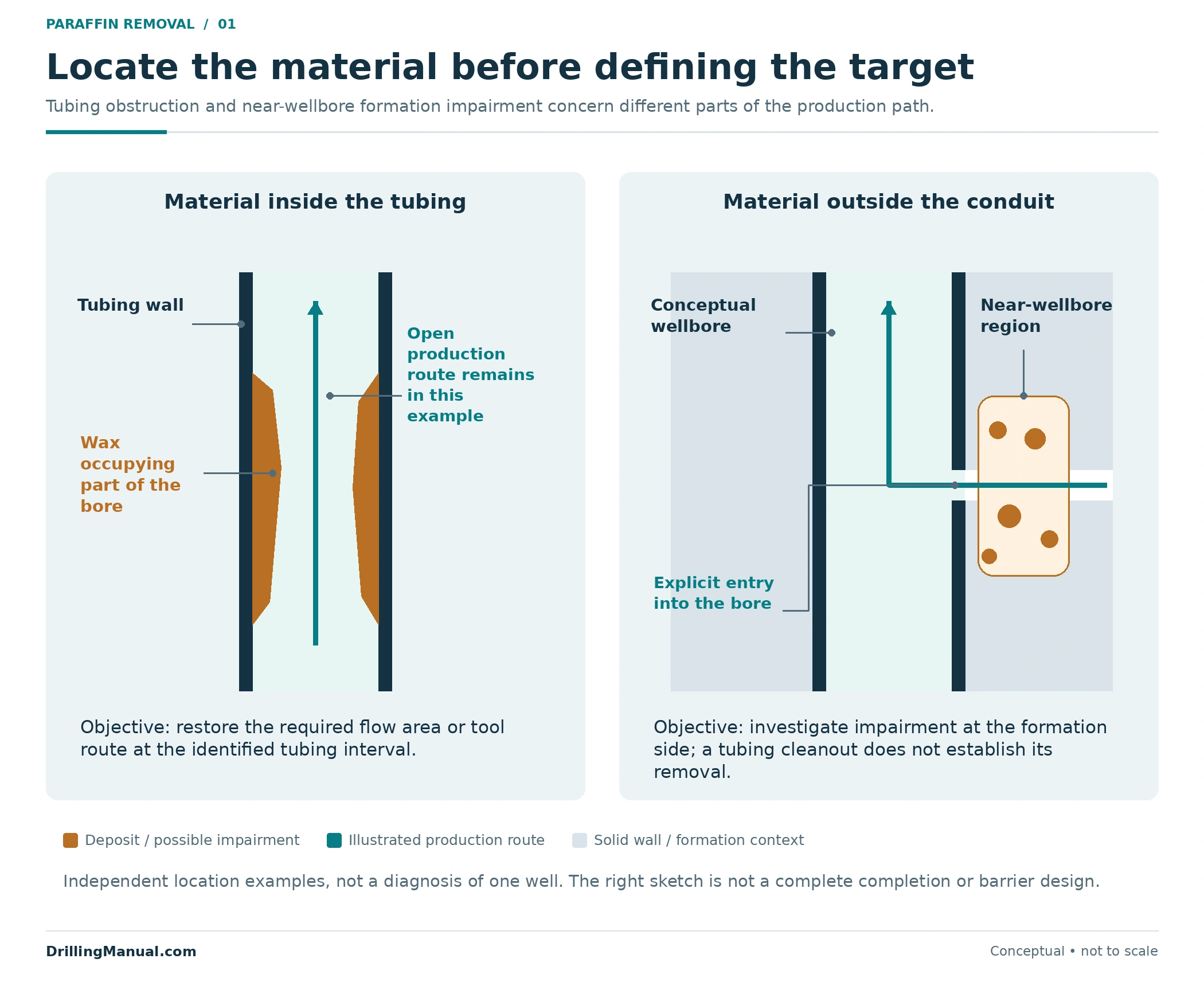
A deposit on the tubing wall occupies part of a conduit. Material in the near-wellbore formation affects a different part of the production path. Clearing tubing cannot be assumed to remove formation impairment; equally, evidence of formation damage does not establish that a tubing restriction exists. The two source passages support keeping these targets separate before discussing treatment access. [1, physical p. 400] [2, physical/visible p. 230]
Locate the concern as specifically as the evidence allows: an identified tubing interval, a completion component, or a suspected near-wellbore region. Then distinguish an observed limit from its explanation. For example, an assembly failing to reach its destination establishes an access problem for that attempt; it does not chemically identify the material encountered. The completion’s internal profile and the assembly involved remain part of the interpretation. [1, physical p. 401] [3, p. 80]
| Available observation | Useful contribution | Question still open |
|---|---|---|
| Reduced production under recorded conditions | Identifies a performance change to investigate. | Where is the restriction, and is wax responsible? |
| Restricted passage at a reported depth | Identifies a problem along the attempted route. | Is the cause a deposit, installed profile or another access constraint? |
| Recovered material with documented origin | Provides material for deposit analysis. | How representative is it of material elsewhere? |
| Improvement after intervention | Documents a changed outcome under stated conditions. | Which mechanism improved, and what remains? |
The table is an interpretation framework, not a set of diagnostic signatures. A useful description for paraffin removal in oil wells links the observation to a location and states what remains uncertain. “Suspected organic restriction over the documented tubing interval” is a more testable starting point than assigning every production loss to wax.
Identify Wax Before Assigning a Removal Method
The CT manual describes wax/paraffin and other organic deposits associated with changes in pressure and temperature during production. It separately treats inorganic scale, and explains that actual wellbore deposits may combine organic material, scale and formation fines. Consequently, a familiar appearance or previous wax history does not establish the composition of the present obstruction. [1, physical pp. 400–401]
Material identification changes what a candidate treatment is expected to do. A fluid that dissolves one constituent may leave another constituent behind. A mechanical tool acts on material it can contact, while heat changes the behaviour of susceptible organic material. For paraffin removal in oil wells, the sample’s origin and the remaining uncertainty about the whole deposit should accompany any laboratory result. [1, physical pp. 401–402]
| Material category | Relevant distinction | Selection implication |
|---|---|---|
| Wax or other organic deposit | Response depends on its properties and the conditions at the deposit. | Evaluate the intended softening, dissolution or physical-removal mechanism. |
| Mineral scale | It is an inorganic deposit, not another name for wax. | A wax-removal assumption cannot be carried across without material evidence. |
| Mixed deposit | Organic material, scale and fines can coexist. | Consider what each candidate removes and what may remain. |
| Hydrate | Gas molecules are held in a water-molecule lattice. | It is a distinct blockage problem; wax identification and treatment logic do not establish a hydrate response. |
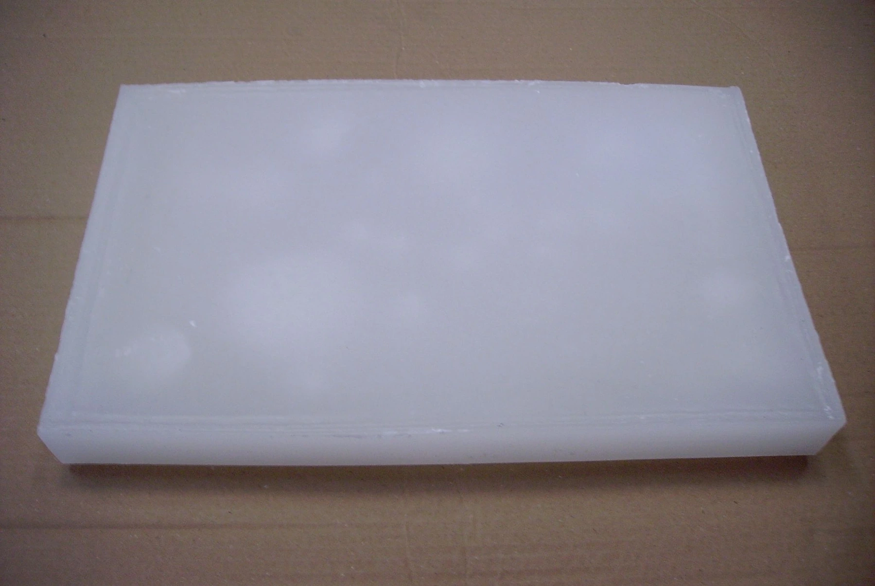
These distinctions come from the manual’s deposit-characteristics discussion. They are not a visual identification guide or a chemical recipe. The photograph below shows a separately sourced paraffin block; it is not a sample recovered from an oil well. [1, physical pp. 400–402]

How a Wax Layer Changes the Open Bore
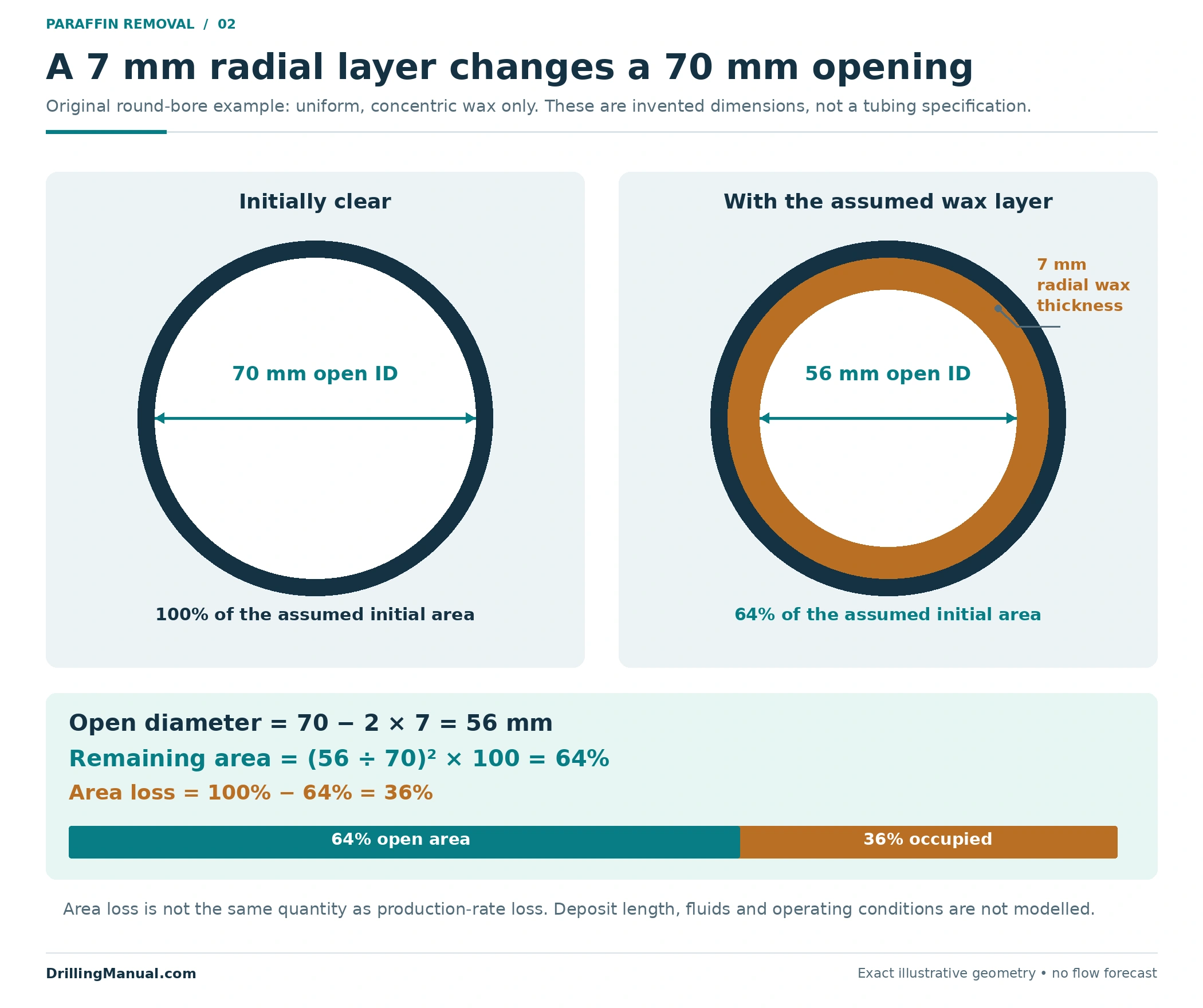
Consider an invented, perfectly round tube with an initially clear internal diameter of 70 mm. Assume a uniform wax layer 7 mm thick around the entire circumference. The remaining open diameter is 70 − 2 × 7 = 56 mm. Because circular area varies with diameter squared, the remaining area fraction is (56 ÷ 70)² = 0.64: 64% open area and 36% area loss.
This calculation is geometry, not a field measurement, a tubing specification or a production prediction. It assumes a concentric, uniform layer and contains no information about deposit length, roughness, fluid properties or producing conditions. It therefore cannot establish that the well will lose 36% of its production. Its purpose in paraffin removal in oil wells is to show why a layer on both sides of the bore can materially change the opening. The source supports the flow-area concern; the numbers are original illustrative assumptions. [1, physical p. 400]
Access Controls Paraffin Removal in Oil Wells
Knowing a deposit exists does not establish that the selected tool or fluid can reach it. The CT planning inputs include internal diameter versus depth, installed completion hardware, the directional survey, annulus-fluid properties and the surface configuration. These details connect the intended treatment location to a physically available route. [1, physical p. 401]
A tubing-size label is insufficient where the path includes smaller completion profiles or an uncertain obstruction. The slickline gauge cutter and tubing drift article explains how passage evidence is bounded by the body and route actually checked. Here, that evidence contributes to method feasibility; it does not replace deposit identification or demonstrate complete cleaning. ENI’s descriptive gauging passage explicitly considers completion components and minor obstructions. [3, p. 80]
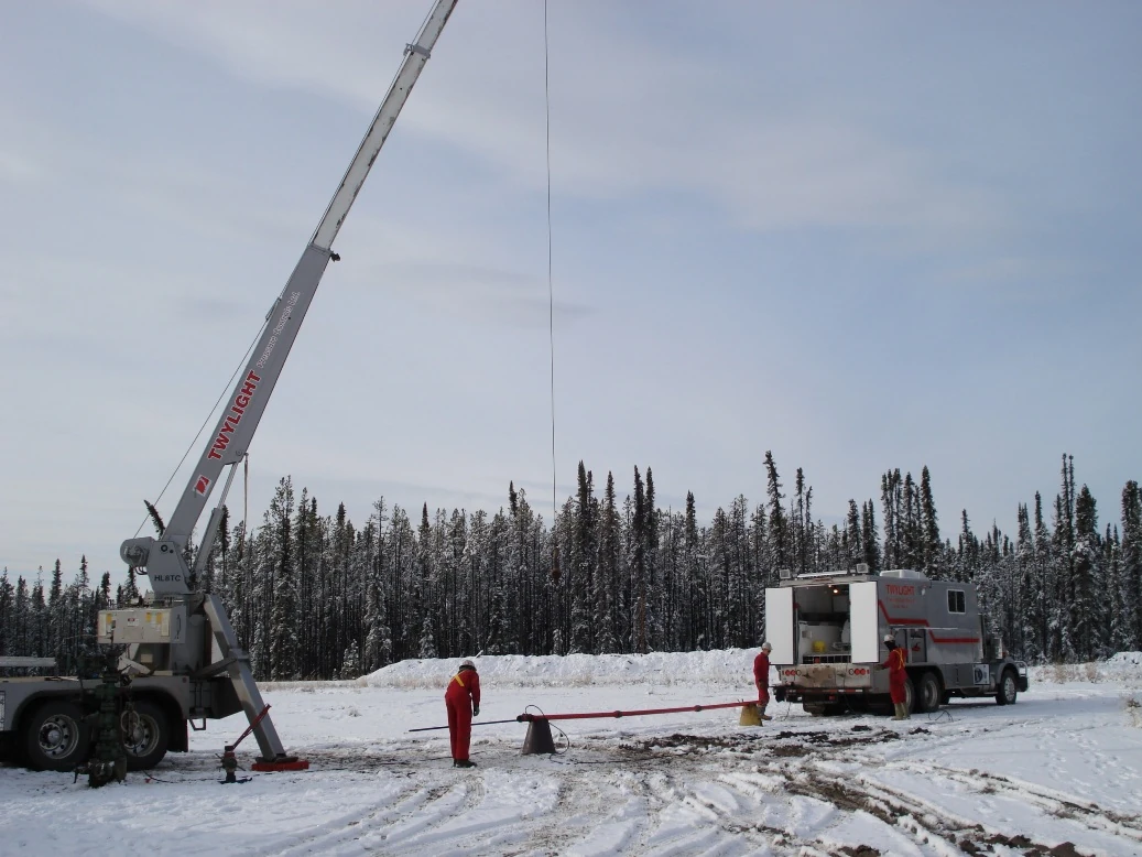
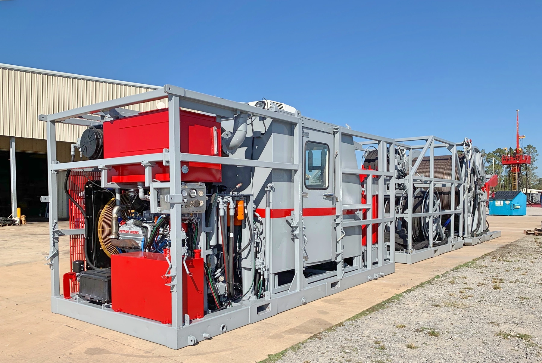
Access for paraffin removal in oil wells also includes fluid delivery and the intended return route. The coiled tubing guide provides broader equipment context, while the present question is whether a proposed arrangement can contact this deposit and handle the resulting material. A photographed intervention unit cannot answer those well-specific questions.

Compare Mechanisms for Paraffin Removal in Oil Wells
Mechanical Contact and Hydraulic Action
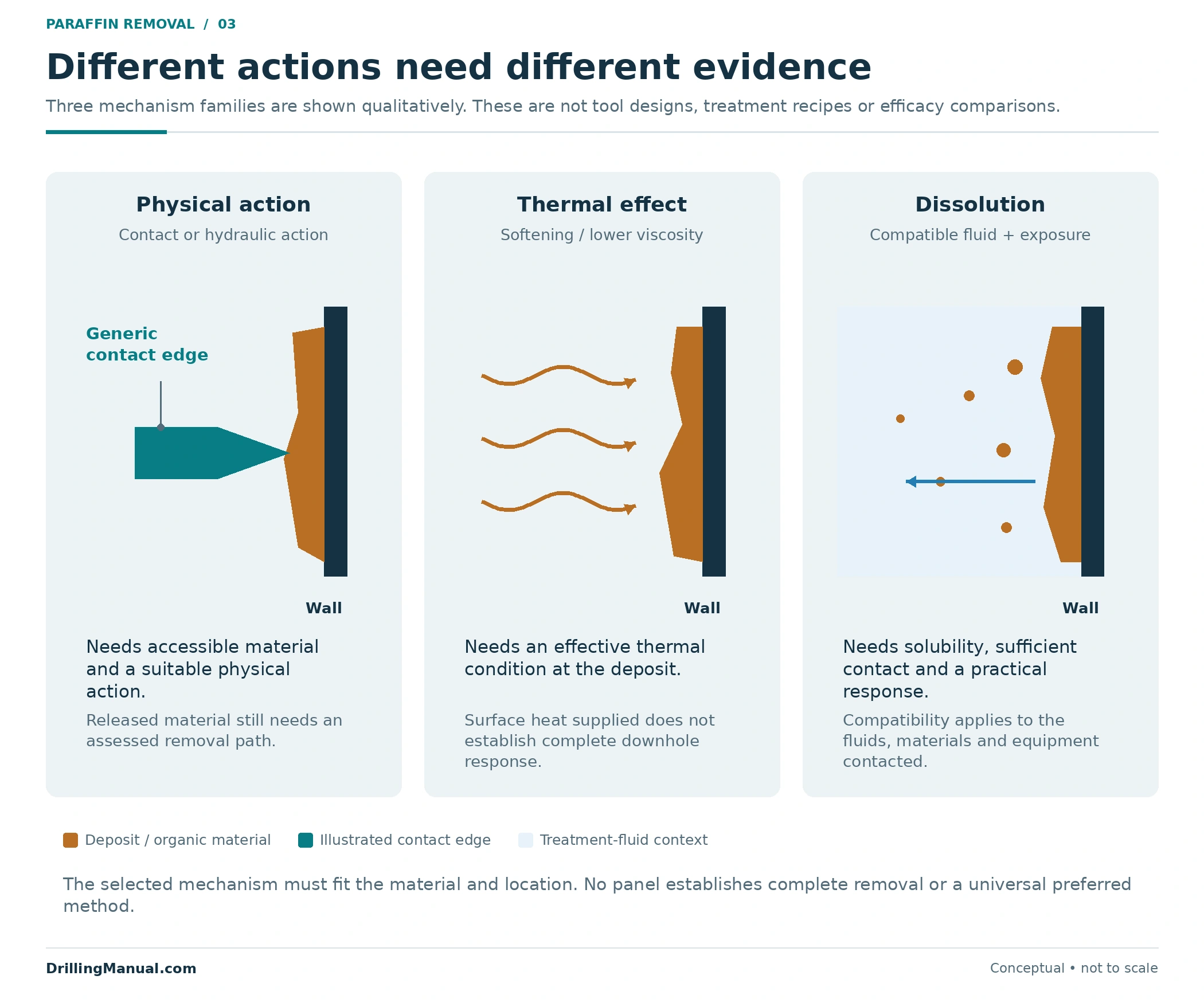
The intervention handout identifies light-paraffin removal as a possible gauge-ring function. ENI similarly describes cutter-type gauges capable of removing minor obstructions. These narrow statements support physical contact as one candidate mechanism; they do not establish that every deposit can be scraped out or that a passage observation represents a fully restored wall profile. [4, p. 208, §180] [3, p. 80]
Hydraulic jetting is another physical mechanism. The CT manual distinguishes coverage of softer deposits from impact or cutting action on harder material, and relates feasibility to hydraulic and mechanical performance. Treating all physical removal as one interchangeable service hides these differences. The intended action, accessible surface and transport of released material all need consideration. [1, physical pp. 402–404]
The Thermal Effect Must Reach the Deposit
Heat can soften organic deposits or lower their viscosity sufficiently for removal or return to solution. The relevant condition is at the affected interval. The manual specifically identifies a possible shortfall in which heated fluid reaches the deposit with enough heat for only partial removal. Surface heating alone therefore does not demonstrate the intended downhole effect. [1, physical pp. 400–401, 404]
In paraffin removal in oil wells, a thermal proposal needs a credible connection between delivery conditions, deposit response and material movement. “Heated fluid was pumped” records an activity. It does not measure how much wax was softened, whether the full affected interval was contacted or whether the released material left the well.
Chemical Dissolution Needs Solubility and Contact
A dissolution treatment requires a deposit that is soluble in the selected fluid, adequate contact and sufficient time. The CT manual also includes composition, deposit volume, well conditions and compatibility with contacted fluids, materials and equipment. Some deposits dissolve too slowly for a practical treatment, even when dissolution is possible in principle. [1, physical p. 402]
Successful paraffin removal in oil wells therefore depends on more than a chemical’s general description. The review must connect the actual material to the expected contact conditions. The manual notes that temperature can affect dissolution and corrosion potential together; improving one aspect cannot be assumed to make the overall proposal acceptable. [1, physical p. 402]
| Candidate mechanism | Intended effect | Evidence needed for this deposit | Important limit |
|---|---|---|---|
| Mechanical contact | Disturb or remove accessible material physically. | Deposit location, accessible geometry and applicable tool function. | Passage does not measure every remaining wall deposit. |
| Hydraulic action | Contact, dislodge or cut material with fluid action. | Delivery, coverage, hydraulic feasibility and material transport. | Circulation alone does not establish effective action everywhere. |
| Thermal action | Soften susceptible organic material or assist its return to solution. | Expected conditions at the deposit and the resulting material behaviour. | Delivered heat may support only partial removal. |
| Chemical dissolution | Dissolve a compatible deposit fraction. | Composition, contact, practical response and compatibility. | Unresponsive constituents can remain. |
The comparison summarizes the cited mechanisms, not a ranking or a prescribed combination. A method becomes a candidate because its expected action addresses the identified material and location. It becomes a defensible proposal only when the access, delivery and remaining-well requirements also fit. [1, physical pp. 400–404]
Delivery Can Be the Limiting Step
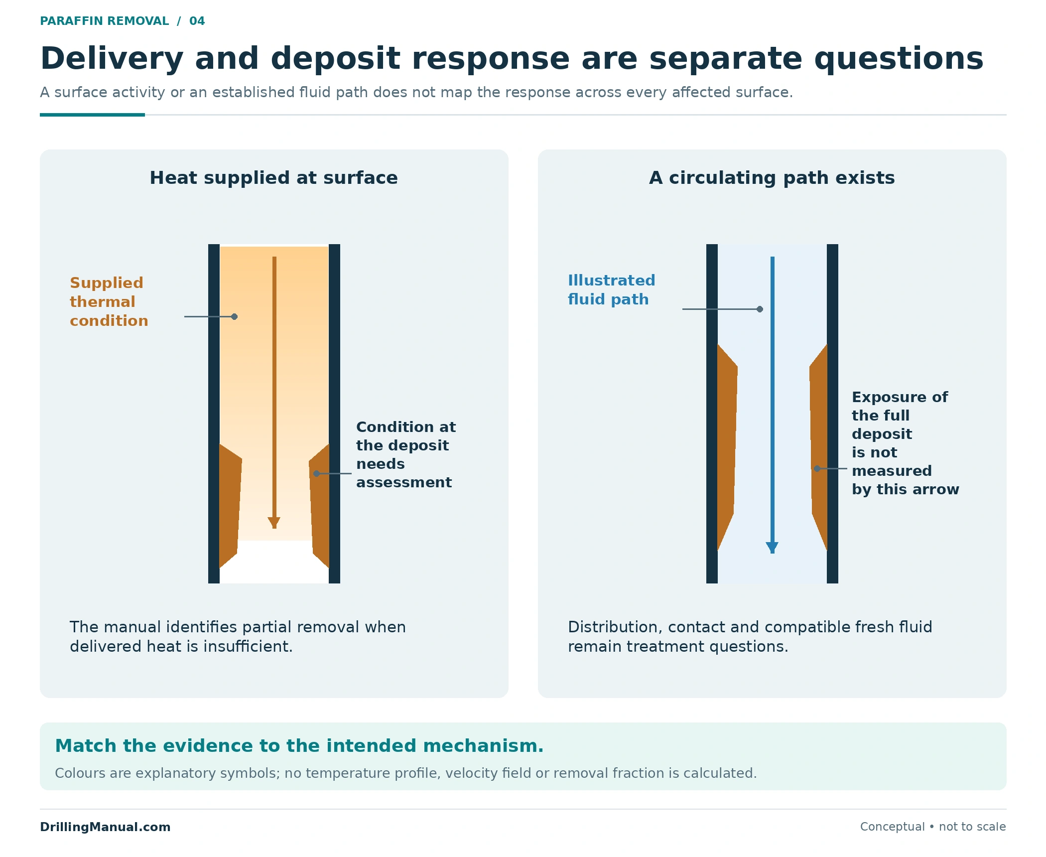
The CT manual’s discussion of distribution and uncontaminated-fluid contact explains why bulk pumping and effective deposit contact are different observations. A return stream establishes that a fluid path exists; it does not map the exposure of every affected surface. Similarly, partial thermal response may leave material even though the surface equipment delivered heated fluid. [1, physical pp. 402, 404–405]
For paraffin removal in oil wells, delivery should be assessed against the particular mechanism: physical contact where material is to be disturbed, suitable thermal conditions where softening is intended, or fresh compatible fluid where dissolution is expected. These are separate questions even when one proposal combines several effects. [1, physical pp. 400–404]
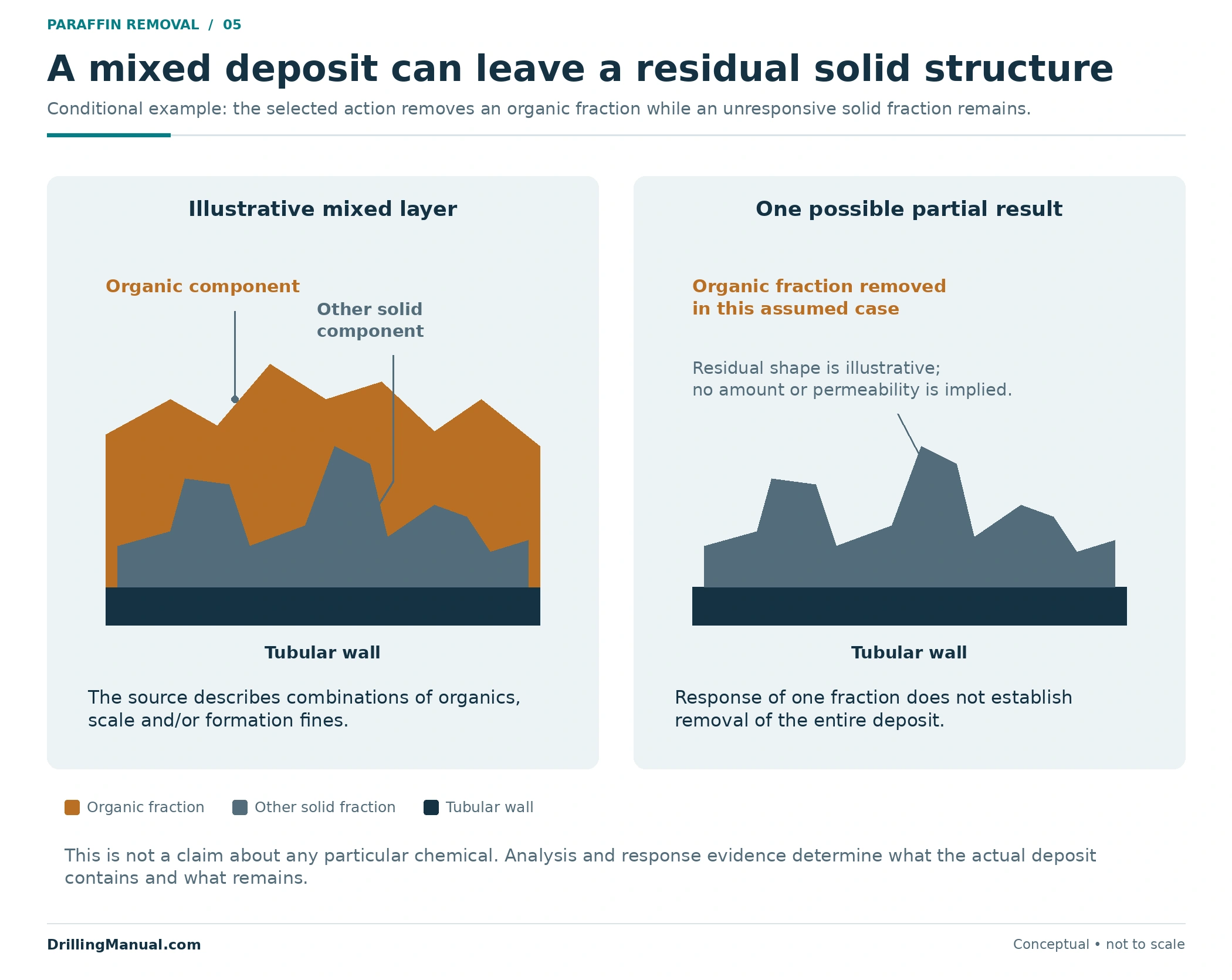
Mixed deposits make partial response especially important. If a selected treatment removes an organic fraction while an inorganic fraction remains, the visible change is real but the whole obstruction has not necessarily disappeared. This is a conditional illustration of the manual’s mixed-deposit warning, not a claim that any named fluid removes only one component. [1, physical pp. 401–402]
The related completion and workover fluid testing guide covers fluid-quality checks. Those checks serve a different purpose from demonstrating that a proposed treatment will respond appropriately to the recovered deposit. Both types of evidence should retain their actual scope.
Define the Result of Paraffin Removal in Oil Wells
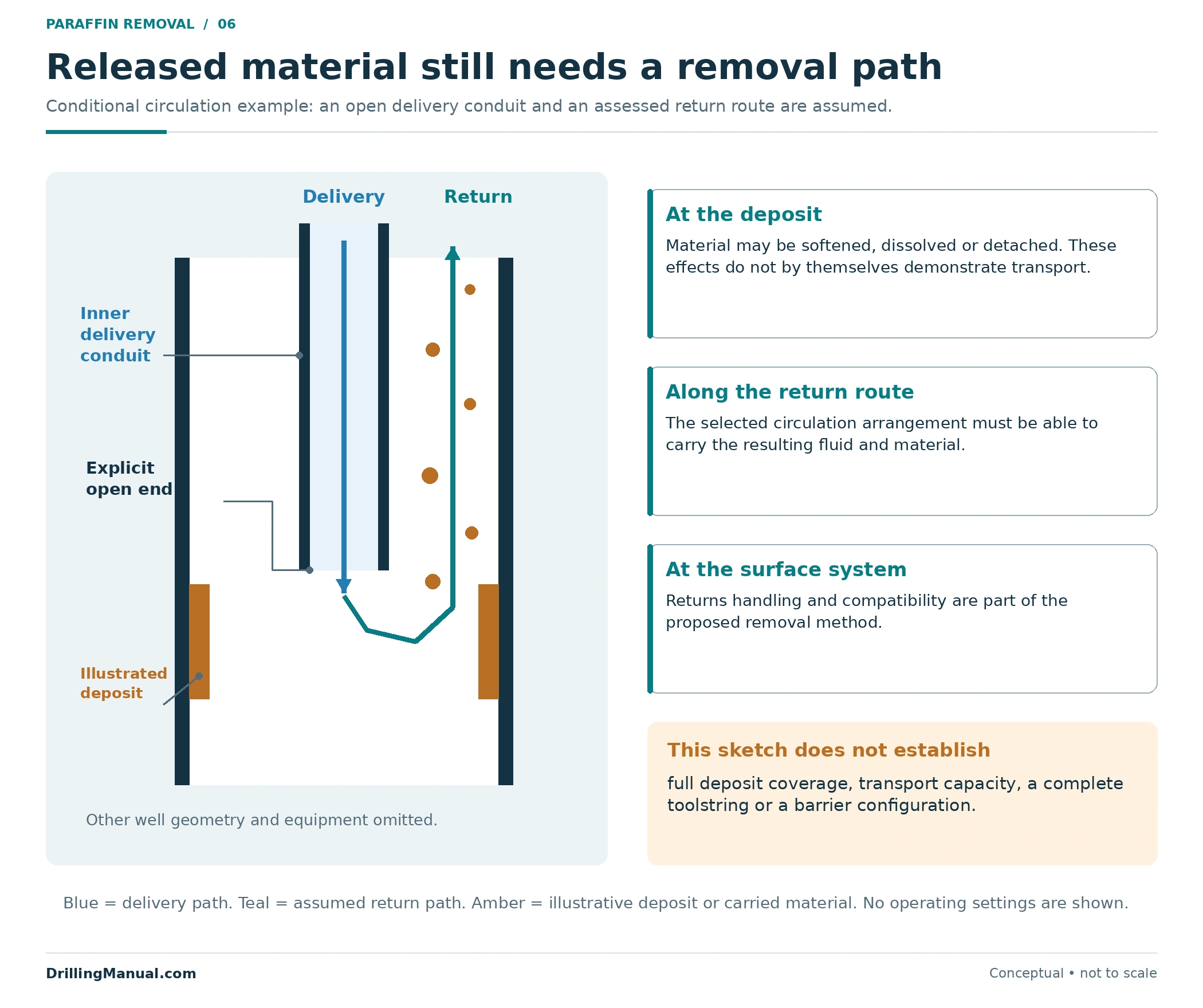
Softening, detachment, dissolution and removal from the well describe different outcomes. Where circulation is the selected transport mechanism, released material needs an available, compatible return system. The manual addresses circulation capacity, returned treatment fluid, solids-laden returns and surface-equipment compatibility. It does not make treatment at the deposit equivalent to completed transport. [1, physical pp. 400, 403–405]
The conceptual return-path drawing shows only fluid movement through an open delivery conduit and back through the surrounding space. It omits the complete completion, barrier arrangement and toolstring design. The surface equipment guide and CT pressure-control equipment guide provide related equipment context; neither the drawing nor those links select a well-specific setup.
| Defined objective | Evidence suited to that objective | Limit to preserve |
|---|---|---|
| Recover access to a stated destination | Documented passage of the relevant assembly through the identified route. | Access is not a complete deposit inventory. |
| Remove identified material | Material evidence, treatment response and the documented removal/return path. | A recovered sample does not account for everything remaining. |
| Improve production performance | Comparable production records with operating conditions stated. | A rate change alone does not isolate its cause. |
| Prepare for subsequent completion work | Evidence addressing that next assembly’s access and functional requirements. | A generic cleanout claim does not define readiness. |
This is an original evidence framework built from the sources’ distinctions between deposits, access, treatment response and transport. The wellbore cleanout before recompletion article develops the separate debris-and-readiness question. Paraffin removal should have its own measurable purpose before it is used as evidence for another task.

Build a Candidate Brief for Paraffin Removal in Oil Wells
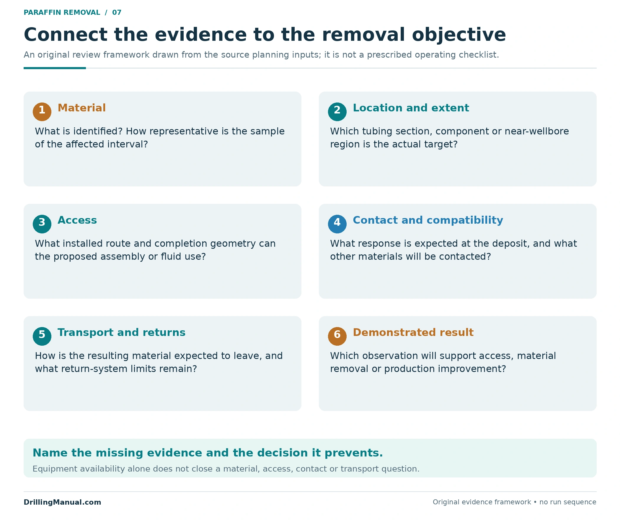
A concise brief connects six information groups: deposit identity and representativeness; location and extent; completion access; expected contact conditions and compatibility; material transport and returns; and the result to be demonstrated. These groups synthesize the CT planning inputs and treatment discussion without reproducing an operating program. [1, physical pp. 401–405]
Where information is missing, state the decision it prevents. Uncertain composition affects the proposed response. Uncertain reach affects delivery. Uncertain return capability affects whether liberated material can be removed as intended. The broader workover operations guide helps frame intervention scope, but equipment category alone cannot resolve these deposit-specific uncertainties.
Recurrence Monitoring After Paraffin Removal in Oil Wells
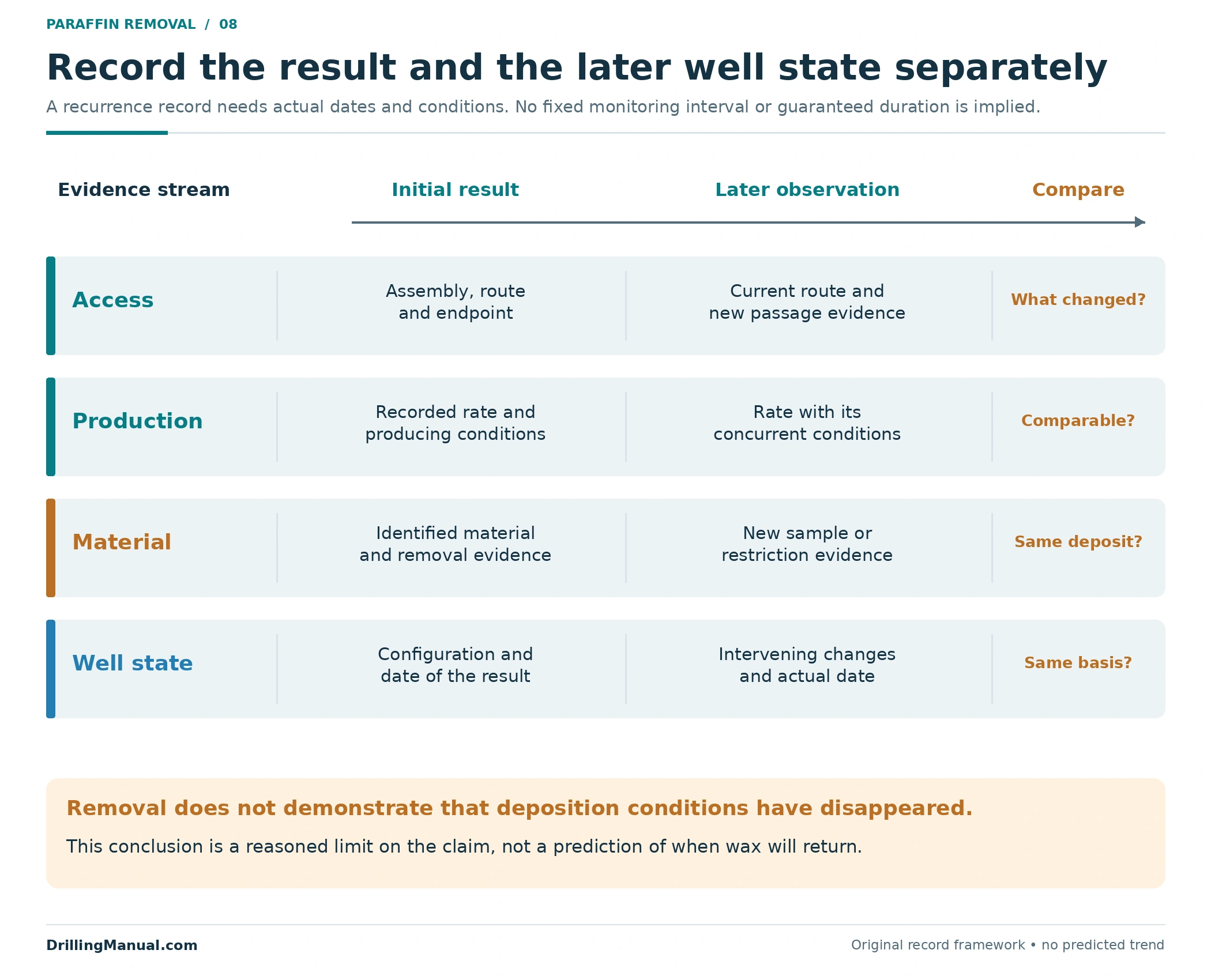
Removing material does not, by itself, demonstrate that the conditions associated with its deposition have changed. That is an inference from the manual’s connection between organic deposits and producing conditions, not a supplied recurrence formula. A result from paraffin removal in oil wells and a recurrence-management claim therefore require different evidence. [1, physical pp. 400–401]
Record subsequent access observations, production under documented conditions and new material evidence separately. Their dates matter: an initial improvement and a later restriction describe different states. No fixed interval, guaranteed duration or universal rate threshold follows from the cited pages. The purpose of the record is to reveal whether the original objective remains satisfied and which uncertainty has returned.
Frequently Asked Questions
What is the best method for paraffin removal in oil wells?
There is no universal choice in the supplied sources. The candidate must fit the deposit’s properties and location, the completion route, achievable contact conditions and the intended result. Mechanical contact, hydraulic action, heat and dissolution address different mechanisms and can have different limits. [1, physical pp. 400–404]
Can appearance distinguish wax from mineral scale?
Appearance alone cannot resolve a mixed deposit’s composition. The manual explicitly describes mixtures containing organic material, scale and formation fines and calls for deposit analysis. A source-identified photograph of wax is useful context, but it cannot identify material recovered from another well. [1, physical p. 401]
Why might heated fluid produce only partial removal?
The temperature effect at the deposit may be insufficient for the intended response. The manual identifies this as a possible delivery shortfall. Heat supplied at surface and the response across the full affected interval are different quantities; neither complete contact nor transport is demonstrated by surface heating alone. [1, physical pp. 401, 404]
Does a successful gauge run demonstrate complete wax removal?
No. A gauging tool may remove light paraffin or minor obstructions, but passage establishes a route for that assembly. It does not measure the entire remaining wall deposit or establish that all disturbed material has left the well. [4, p. 208, §180] [3, p. 80]
Do established returns prove adequate treatment contact?
No. Returns demonstrate a circulating path under the observed conditions. The treatment still needs the distribution, contact and practical response described by the manual. Material along less effectively contacted surfaces or unresponsive constituents of a mixed deposit can remain. [1, physical pp. 401–403]
Does recovered production prove a permanent result?
It records performance over the conditions and period observed. It does not establish that every deposit has been removed or that deposition conditions cannot recur. Longer-term conclusions need their own documented observations; the sources provide no universal duration for a successful wax cleanout. [1, physical pp. 400–401]
Book References
- NOV CTES. Coiled Tubing Manual. Copyright 2007–2013; selected pages carry revision date 27 June 2014. “Removing Wax, Hydrocarbon, or Hydrate Plugs,” printed pp. 11-103–11-108, physical PDF pp. 400–405. Used for deposit characteristics, planning inputs, contact, candidate removal mechanisms, delivery limitations and returns. Historical numerical settings and operating instructions are excluded.
- Economides, Michael J.; Dunn-Norman, Shari; and Watters, Larry, editors. Petroleum Well Construction. Supplied Halliburton educational digitization; preface identifies John Wiley and Sons as the original publisher. Physical/visible p. 230, “Near-Wellbore Damage.” Used only for paraffin as one possible formation-impairment cause, not as a tubing-cleanout procedure.
- ENI S.p.A., Agip Division. General Wireline Procedures Manual, STAP-P-1-M-7110, Revision 0, 28 June 1999, 318-page copy. Printed/manual and physical PDF p. 80, §9.2 “Tubing Gauging.” Limited use: completion geometry and the descriptive minor-obstruction function of cutter-type gauges.
- Well Intervention Pressure Control handout, identified by the supplied filename; author, publisher, edition and date unverified. Physical/printed p. 208, §180.0 “Drift Runs/Gauge Cutters.” Limited use: light-paraffin removal and drift/gauging functions. Tool-size examples, running instructions and the separate safety-valve section are excluded.