A slickline gauge cutter can provide useful evidence that a defined body has travelled through the tubing to a stated depth. That evidence matters before another intervention tool is committed to the well. It does not automatically qualify every smaller tool, certify a completely clean bore or prove access below the depth actually checked. The distinction follows from the different questions covered by tubing dimensions, completion restrictions and toolstring flexibility in the supplied wireline manual. [1, pp. 22, 80–83]
A useful review asks more than “Did the gauge pass?” Ask which assembly passed, through which installed components, how its depth was referenced and how closely it represents the next assembly. A short gauging section and a long intervention body can share an outside diameter while presenting different geometry to the same curved route. A service tool can also have a running attachment wider than its working body. [1, pp. 22, 44, 82]
This article examines slickline gauge cutter evidence as part of a passability assessment. It uses the manuals for engineering principles, while keeping their historical operating instructions separate from current well-specific programs. No generic cutter diameter, allowable force, jarring response or running sequence is prescribed.
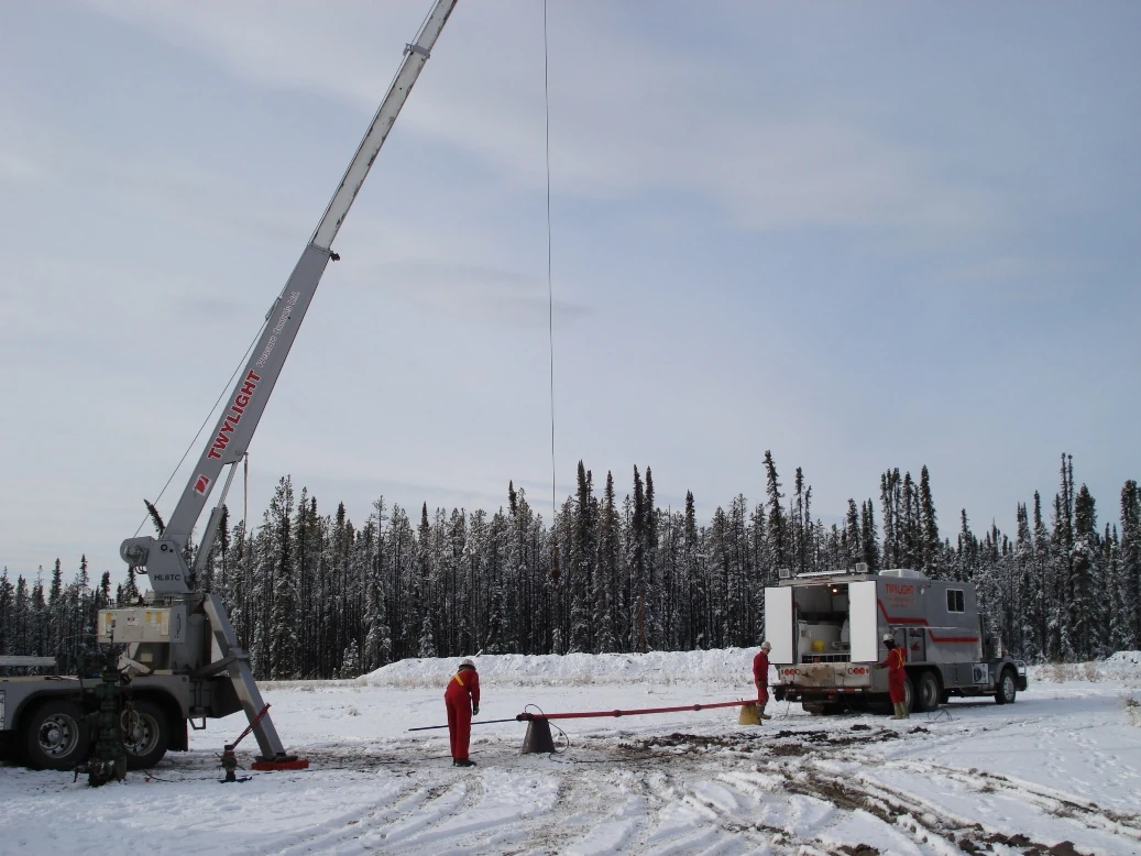

What a Slickline Gauge Cutter Actually Tests
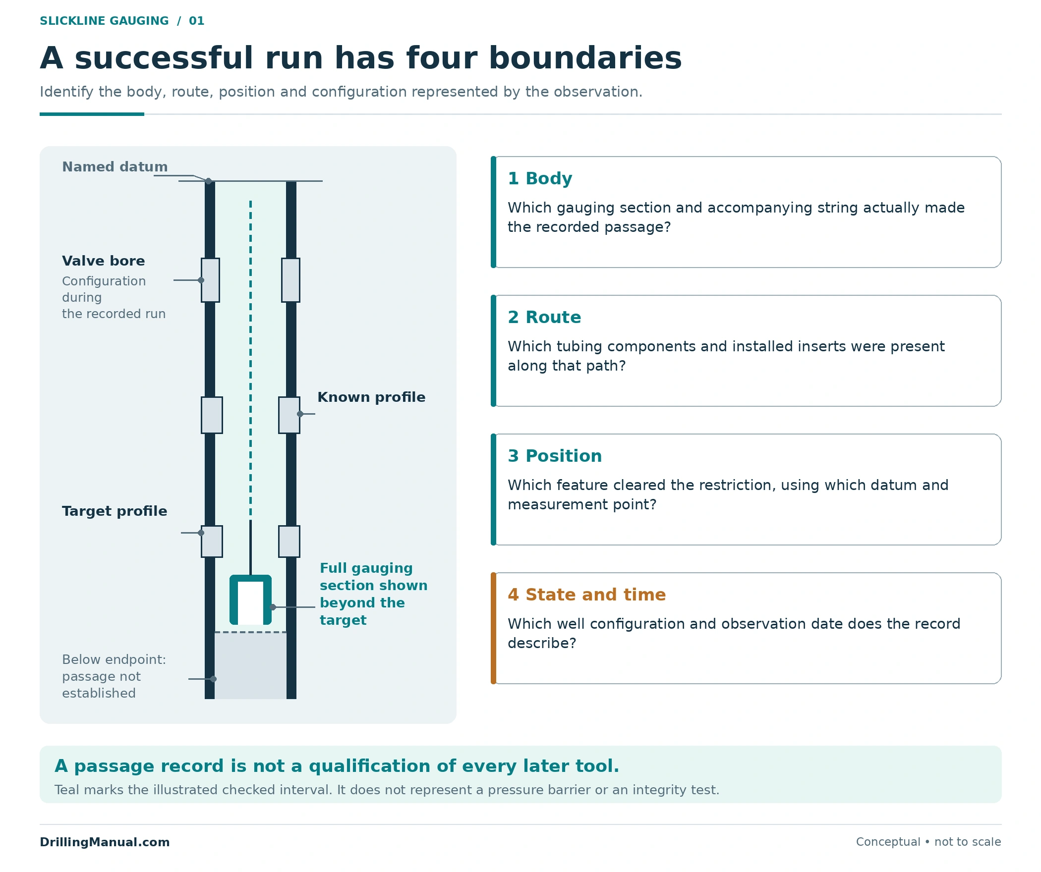
The ENI manual describes tubing gauging as a check on the internal route, including tubing connections and the diameters and locations of completion components such as landing nipples, crossovers and subsurface safety valves. The pressure-control handout identifies gauge cutters as tools that can also be used for drift runs. These are checks on passage through an assembled well, whose restrictions are not represented by the tubing’s nominal size alone. [1, pp. 80–81] [2, p. 208, §180]
For a particular run, the direct observation is passage or failure to establish passage of the gauging assembly over a recorded route. The interpretation must remain tied to the section that actually cleared each feature. A reported tool-bottom depth is not, by itself, proof that every wider section above that point has crossed the same restriction. Tool geometry and the measurement reference must be understood together. This is a geometric interpretation of the manual’s requirements for string design and a defined depth reference. [1, pp. 44, 81–82]
| Recorded observation | Claim it can support | Claim still requiring other evidence |
|---|---|---|
| The defined gauging section cleared the target profile. | That section passed that profile in the recorded configuration. | A different assembly will also pass. |
| The assembly reached a documented endpoint. | Access was demonstrated to the stated endpoint and reference. | The bore below that endpoint is accessible. |
| A tool travelled through a valve bore. | Passage occurred through the valve’s configuration at that time. | The valve will close and seal satisfactorily. |
| Material was recovered with the tool. | That material was present on or within the recovered assembly. | All similar material has been removed from the well. |
A successful slickline gauge cutter run is not a continuous internal-diameter measurement. Several different openings could admit the same body. Passage therefore does not supply the exact clearance at each connection, reveal the full shape of an irregular opening or establish how much larger another body could be. Treating the result as a dimensional map would add information that the observation did not contain. This distinction also keeps an in-well access assessment separate from a tubular-manufacturing drift specification.
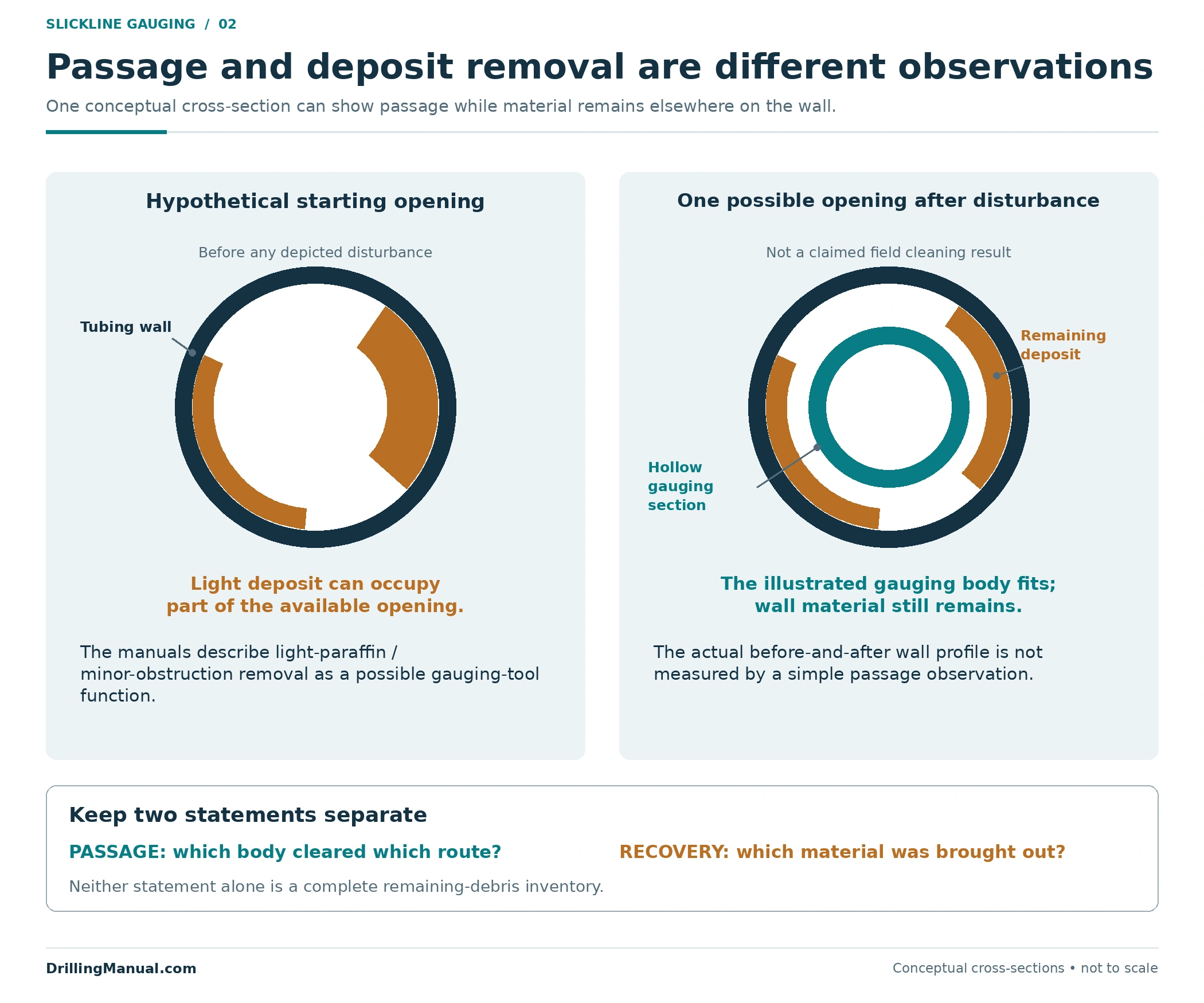
Gauging and Light Deposit Removal Answer Different Questions
A slickline gauge cutter may combine a dimensional function with limited cleaning action. The handout specifically mentions light paraffin removal, while ENI discusses cutter-type gauges that can address minor obstructions. Consequently, an observed passage may describe a route after some material has been disturbed. It need not describe the untouched bore that existed before the run. [2, p. 208, §180] [1, p. 80]
Keep those observations separate. “The gauging section passed” concerns the body’s route. “Material was brought out” concerns recovered contents. Neither statement alone measures the deposit remaining around the entire circumference or demonstrates that released material has left the well. This is the boundary between a passage observation and a broader cleanout claim, not a reason to discard the observation.
Read the Route Before Reading the Gauge Result
Begin the interpretation with the actual completion profile. The manual calls for component internal diameters, lengths and depths, tubing information, toolstring design, a deviation report and recent well records. The useful output is an identifiable route through the installed equipment, rather than a single tubing-size label. A component that was removed, replaced or fitted with an insert changes the comparison. [1, pp. 44–45]
A landing nipple belongs on that route as a specific profile at a documented depth. A subsurface safety valve belongs on it in the configuration through which the tool must pass. The manual identifies both as relevant to gauging; identifying their names without their applicable internal dimensions leaves the access question unfinished. [1, pp. 80–83]
The depth reference is equally important. ENI asks for the relation between the surface measurement reference and a defined completion reference. When a report and a schematic use different reference points, their numbers should not be compared as though they share a zero. The required comparison is between the demonstrated position of the relevant gauge section and the position of the feature being assessed. [1, pp. 81–83]
| Route information | Why it changes the interpretation |
|---|---|
| Installed components and inserts | They define the route that existed during the observation. |
| Component bore, profile and axial length | A short opening and a long restricted section are different geometries. |
| Depth datum and tool measurement point | They connect the reported depth to the feature actually cleared. |
| Deviation and curvature information | They help assess whether a different rigid body is represented by the gauge. |
| Latest intervention and configuration record | They identify whether the comparison still describes the present well. |
Define the intended endpoint before deciding whether an observed restriction is unexpected. A planned locating profile and an unexplained loss of access are not equivalent findings. If a feature is the intended stopping location, the record can support reaching that feature without showing that the assembly could pass through it. Conversely, a job requiring access below the feature needs evidence relevant to that lower route. The manual’s separate attention to profile diameter, profile depth and the locating point supports making this distinction explicit. [1, pp. 80–82]

Compare the Complete Assembly with the Slickline Gauge Cutter
The next comparison is between two assemblies, not two catalogue headings. Identify the gauging section and the rest of the string that accompanied it. Then identify the next tool’s running geometry, including its connections, shoulders and attached running equipment. Comparing only the service body can overlook the component that controls access. This follows from considering the complete toolstring design required by ENI rather than treating the bottom tool as the entire assembly. [1, pp. 44, 82]
Maximum running outside diameter is one part of that comparison. Its location along the assembly, the length over which it occurs and the shape of transitions also matter to the geometry. The slickline gauge cutter does not become a physical replica of every subsequent tool merely because their stated maximum diameters match. [1, pp. 22, 82]
A familiar application name is insufficient as well. A dump bailer and a tool intended for a sliding sleeve are different service tasks. For passability, each still needs its actual assembled outline and intended route. The present article concerns reaching the destination; it does not establish whether a tool can perform its intended function there.
Rigid Length Changes the Geometry
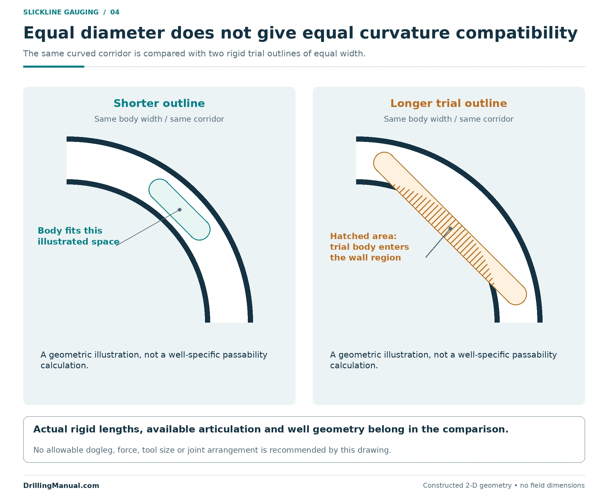
In a curved conduit, a rigid body cannot simply adopt the conduit’s centreline shape. A longer rigid section can require space away from that centreline even when its diameter is unchanged. ENI explicitly addresses rigidity in deviated wells and doglegs, and separately describes knuckle joints as providing toolstring flexibility. Those passages support considering length and flexibility alongside diameter. [1, pp. 22, 82]
Total string length and rigid-section length are different quantities. Two equally long strings can distribute their rigidity differently because their connections and articulating elements differ. Conversely, a short service tool may sit below a longer rigid section that governs the comparison. These are reasons to review the assembled drawing and the actual flexibility provided, not reasons to assume that any jointed string will negotiate the route. [1, pp. 22, 44, 82]
The illustration isolates this geometric relationship. It is not a calculation of a particular well’s allowable dogleg or a recommendation to add joints. Whether a real assembly can traverse the route requires its actual rigid lengths, available articulation and the well geometry. A shorter body fitting the illustrated bend does not establish that the longer outline will fit.
When a Slickline Gauge Cutter Does Not Pass
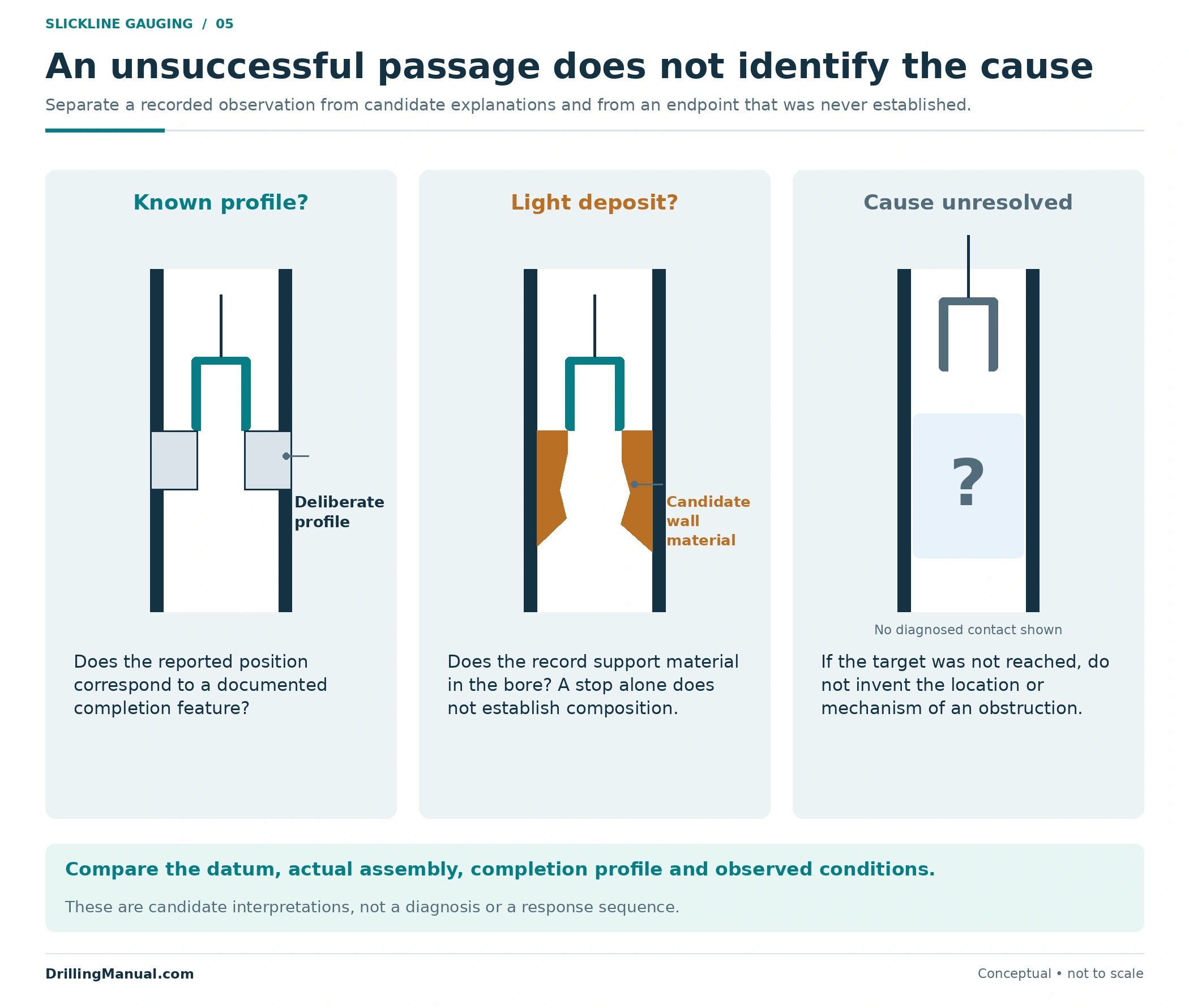
Failure to reach a planned depth is an observation, not a completed diagnosis. The route may contain a deliberate completion restriction, material occupying part of the bore or a geometry that the assembly cannot negotiate. The completion record and the actual run record determine which explanations remain credible. The manual’s treatment of profiles, paraffin and rigidity supports separating these possibilities instead of labelling every unsuccessful passage “scale.” [1, pp. 80–83] [2, p. 208, §180]
Even the wording of the observation matters. “Target depth was not established” does not necessarily identify a hard contact at that depth. “A restriction was encountered at the reported reference” is more specific, but still does not establish its material, shape or cause. Record what was observed before choosing the explanation.
The slickline gauge cutter report can be compared with known profile depths, previous intervention results and any recovered material. ENI’s production-gauging reporting context includes well depth, samples and indications of unusual pull, alongside chronology and well conditions. These are pieces of context; no single one is a universal signature of a particular obstruction. The appropriate response remains governed by the well-specific investigation and approved program. [1, p. 83]
An Original Comparison: Same Diameter, Different Evidence
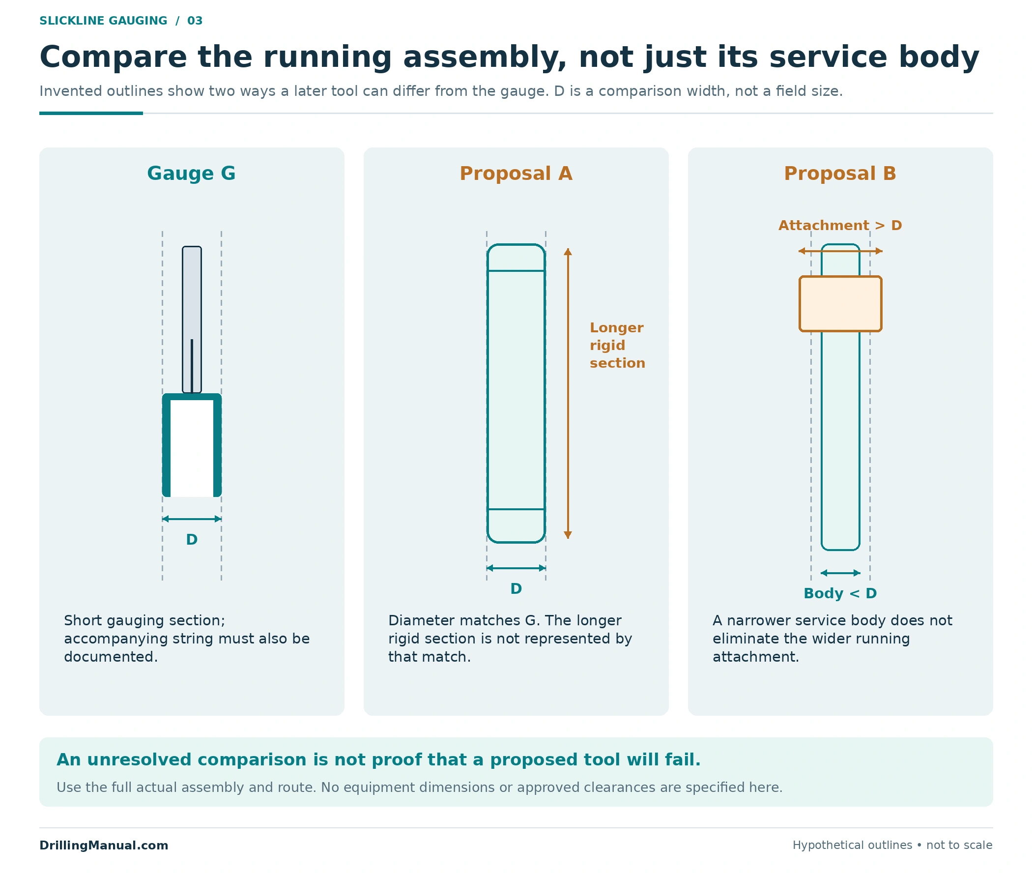
Consider an invented review with no field dimensions. Gauge G has a maximum gauging width labelled D. Its documented assembly traversed the intended route, and its full gauging section cleared the target profile. The report identifies the datum, the components present and the date. Two later proposals are now being compared with that observation.
| Item | Assumed geometry | What the comparison establishes |
|---|---|---|
| Gauge G | Short gauging section of width D, with its accompanying string documented. | Evidence for this actual assembly and recorded route. |
| Proposal A | Maximum body width D, but a substantially longer rigid section. | Diameter matches; compatibility with curvature remains unresolved. |
| Proposal B | Working body narrower than D, but an attached running component wider than D. | The working-body comparison overlooks the widest running component. |
For Proposal A, the existing slickline gauge cutter result does not establish the space needed by the longer rigid section. For Proposal B, it does not establish passage of the wider attachment. Neither conclusion says that the proposal will definitely fail. Both identify the part of the proposed geometry that the existing evidence does not represent. The distinction is an original application of the manual’s toolstring and rigidity principles. [1, pp. 22, 44, 82]
Now suppose Proposal A’s service body is replaced with another design. The comparison must use the replacement assembly, including its connections and actual rigid sections. A previous label such as “same size” cannot carry the approval forward when the geometry being judged has changed.
A Slickline Gauge Cutter Result Has a Time and Configuration
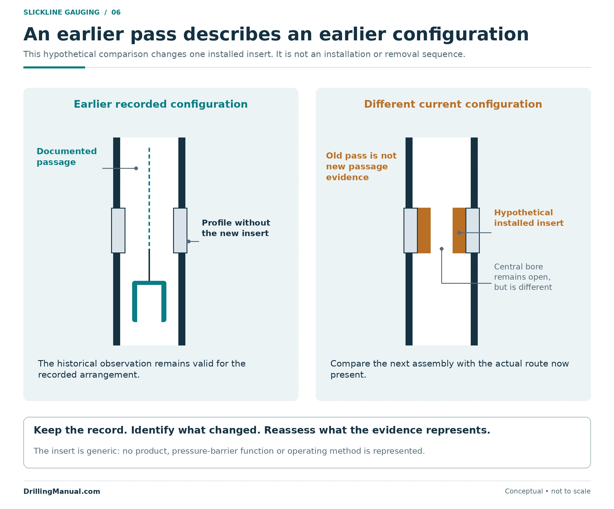
A record can be accurate and still describe a previous well state. ENI treats intervention history and the completion’s configuration after work as information needed for later operations. If an insert has been installed since the gauging run, the formerly open route and the present route are different physical arrangements. [1, pp. 44–45]
This is particularly easy to overlook when the tubing itself remains in place. The wireline-retrievable safety-valve guide is a related equipment reference; the passability review must still identify what is actually installed. Similarly, a tubing-recovery scope and a through-tubing tool route are different descriptions of the completion.
Preserve the original slickline gauge cutter result as a dated observation. Then state the configuration differences and unresolved conditions that affect its use for the next task. Avoid silently converting a historical pass into a statement about the well today. The drawing shows a hypothetical insert change, not an instruction to install or remove equipment.
Turn Slickline Gauge Cutter Evidence into a Tool Comparison
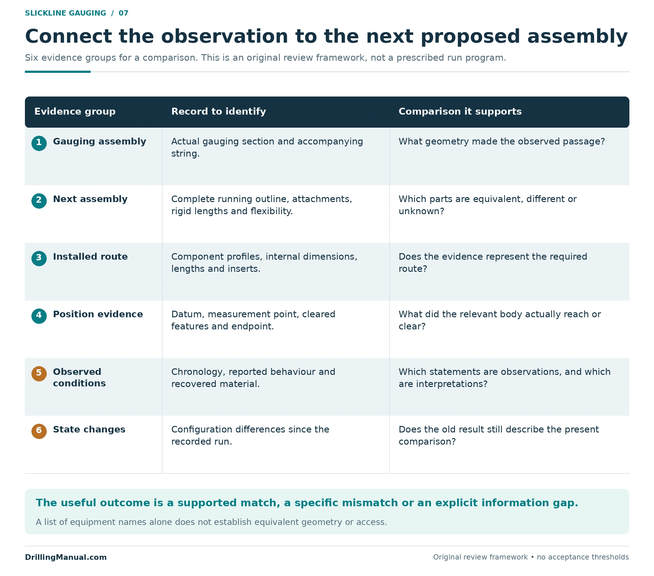
A useful review connects the measured or documented assembly with the completion route and the intended endpoint. The following six information groups are an original synthesis of the manuals’ completion, geometry and reporting requirements. They are not a prescribed operating checklist. [1, pp. 22, 44–45, 80–83]
- Actual gauging assembly: the gauging section, its dimensions and the string used with it.
- Next assembled tool: maximum running outline, shoulders, attachments, rigid lengths and available flexibility.
- Installed route: component profiles, applicable internal dimensions, lengths and current inserts.
- Position evidence: datum, measurement point, endpoint and features demonstrated to have been cleared.
- Observed conditions: chronology, reported behaviour and recovered material, with observations separated from interpretations.
- State changes: differences between the recorded run configuration and the configuration proposed for the next task.
The review may identify good agreement, a specific mismatch or missing information. That is more useful than a bare “drifted” entry. A slickline gauge cutter result contributes to the decision, while the complete job assessment determines whether the next assembly and its intended work are acceptable.

Report the Result Without Extending the Claim
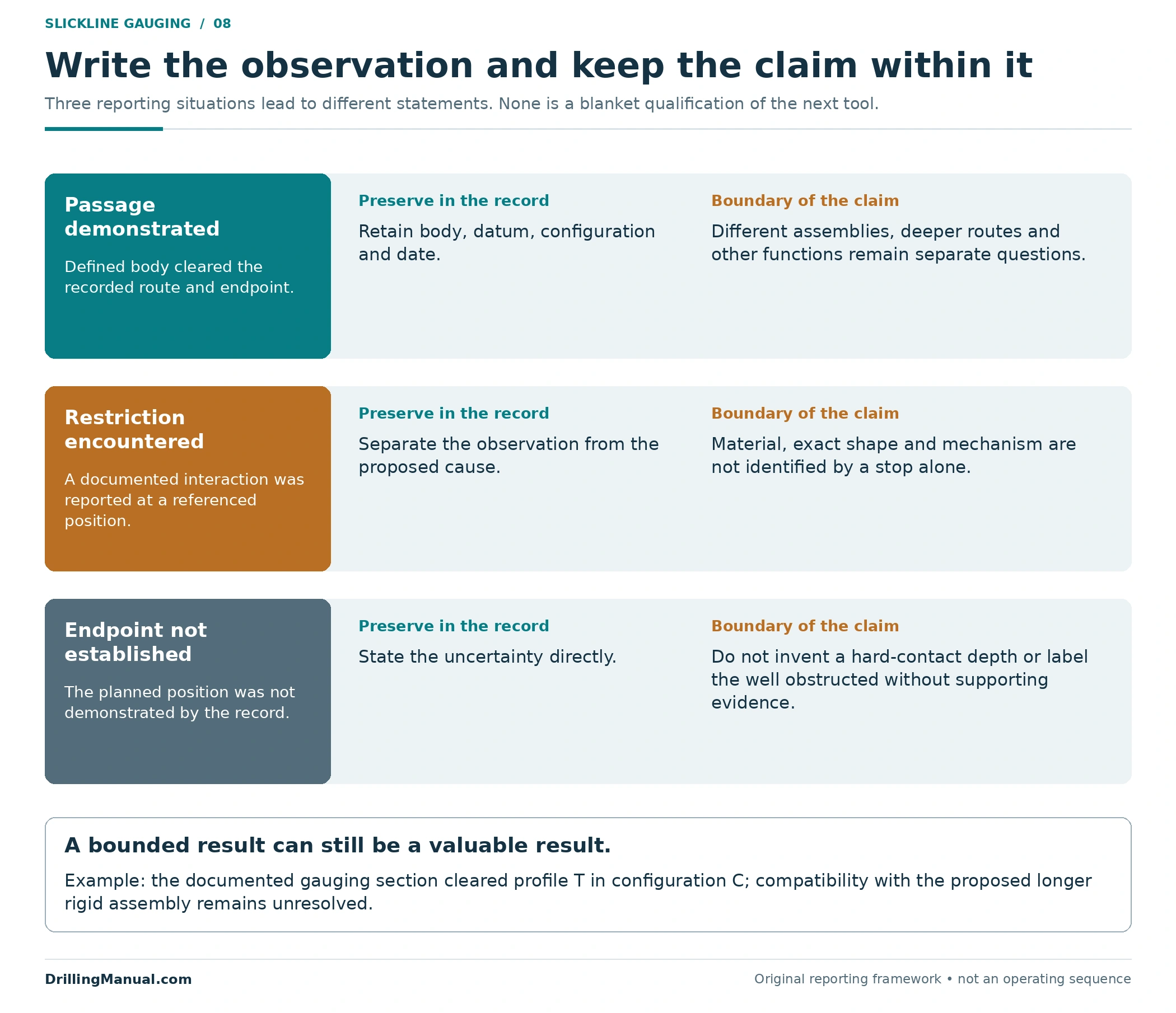
A strong result statement names the assembly, the demonstrated route and endpoint, the datum and the configuration at the time. It also records unresolved events or differences affecting the next tool. This preserves the operational history in a form that a later reviewer can actually compare with another proposal. [1, pp. 44–45, 83]
For example: “The documented gauging section cleared profile T in configuration C; compatibility with the proposed longer rigid assembly has not yet been established.” The symbols are placeholders for actual records, not substitute documentation. The statement keeps the successful observation while identifying the remaining question.
Access evidence also does not answer every choice between intervention methods. The broader workover operations guide addresses service scope and unit capabilities. Here, the essential conclusion is narrower: evaluate the proposed assembly against the evidence actually obtained, and keep unexplored geometry, depth and configuration outside the claim.
Slickline Gauge Cutter and Tubing Drift FAQs
Does a smaller tool automatically pass after a gauge run?
No. A smaller working body can still be attached to a larger running component, and a longer rigid section can interact differently with curvature. Compare the complete assemblies and the same route. [1, pp. 22, 44, 82]
Does a slickline gauge cutter prove the tubing is clean?
It supports a passage observation and may disturb light paraffin or minor obstructions. Passage and recovered material do not, by themselves, establish the condition of every wall surface or account for all remaining debris. [1, p. 80] [2, p. 208, §180]
Why is nominal tubing size insufficient?
The route includes completion components and connections with their own internal geometry. The manual specifically includes nipples, crossovers and safety valves in tubing-gauging considerations. Use the applicable completion profile and installed state. [1, pp. 80–83]
Does stopping at one depth identify a deposit?
No. Compare the observation with known profiles, the depth reference, assembly geometry and other recorded evidence. A stop or an unachieved endpoint does not identify the obstruction’s composition by itself. [1, pp. 81–83]
Does passage through a safety valve prove its integrity?
No. Passage concerns available space in the configuration observed. Closing and sealing are different functions and need their own evidence; they are not demonstrated by a dimensional observation. The manual identifies valve geometry as part of gauging, not gauging as an integrity test. [1, pp. 80–82]
Can an old drift report support a new intervention?
Yes, as historical evidence whose assembly, reference and well configuration can be checked. It should not silently replace a review of changes since that run or differences in the next tool. [1, pp. 44–45, 83]
Book References
- ENI S.p.A., Agip Division. General Wireline Procedures Manual, STAP-P-1-M-7110, Revision 0, 28 June 1999. Supplied 318-page edition. Printed/manual pp. 22, 44–45 and 80–83 correspond to physical PDF pp. 22, 44–45 and 80–83. Historical source used for principles of geometry, completion information, gauging and records; its numerical settings and operating sequences are not reproduced as current instructions.
- Well Intervention Pressure Control handout, identified by the supplied filename; author, publisher, edition and publication date not verified in this copy. Section 180.0, “Drift Runs/Gauge Cutters,” printed and physical PDF p. 208. Use is limited to gauging/drift and light-paraffin-removal concepts.