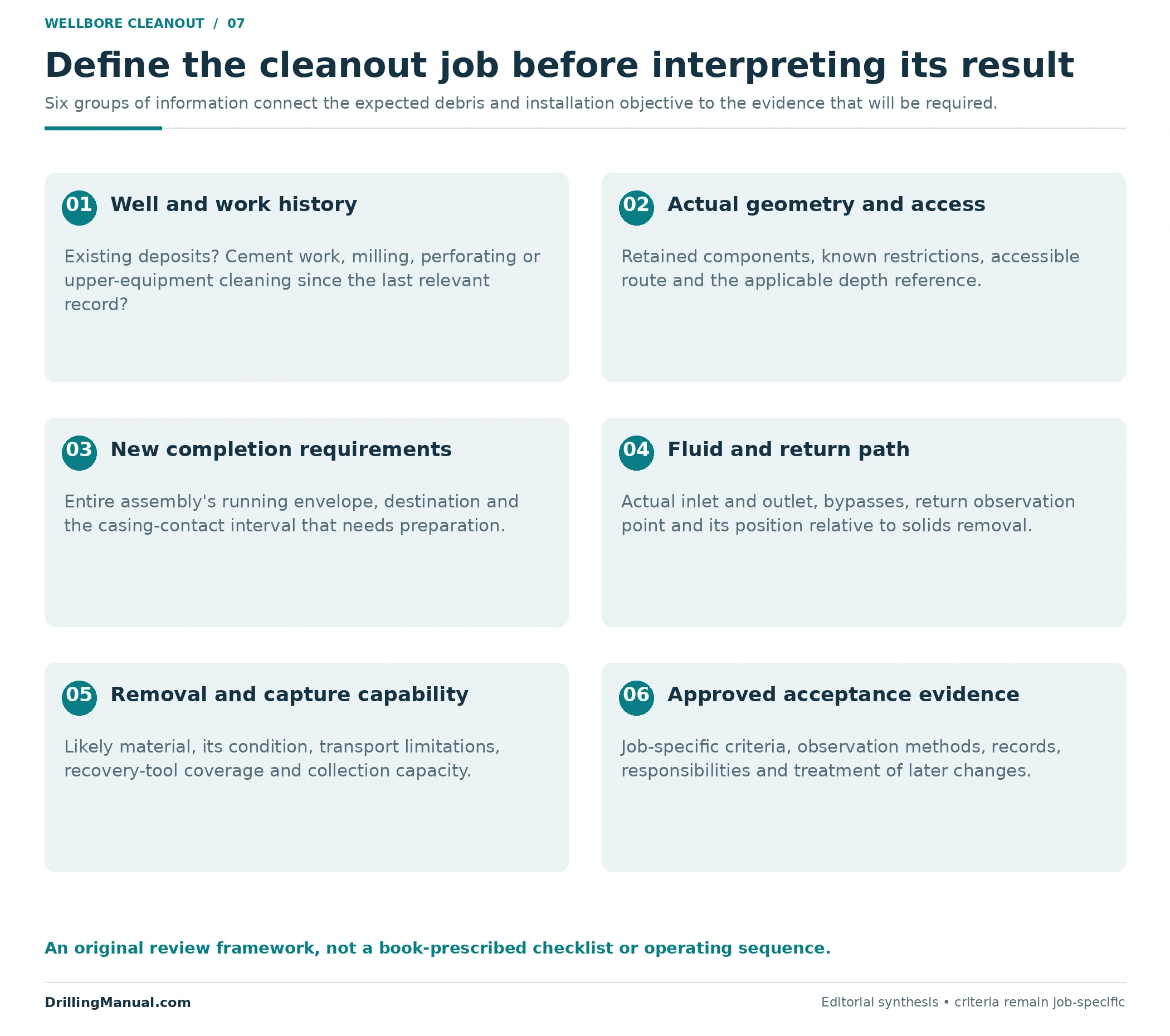
Wellbore cleanout before recompletion has a specific purpose: prepare the route and contact surfaces required by the new equipment, while removing debris that could interfere with installation. The material may include old mud or cement residue, deposits on the casing wall, fragments generated by milling, or debris released while upper well equipment is cleaned. Its origin matters because material attached to a wall, suspended in fluid, and trapped in a basket presents different recovery problems. The supplied fishing catalog connects debris removal directly with completion installation and performance. [2, pp. 111, 114, 134, 153]
A report that says “returns clear” leaves several questions unanswered. Which route was circulating? What interval did the gauge actually traverse? Was the intended casing-contact area prepared? What was recovered, and did later work introduce more debris? This article explains how to connect those observations before landing a new completion. It covers bore readiness and displacement evidence; a produced-sand removal program and laboratory brine-testing procedure require their own treatment.
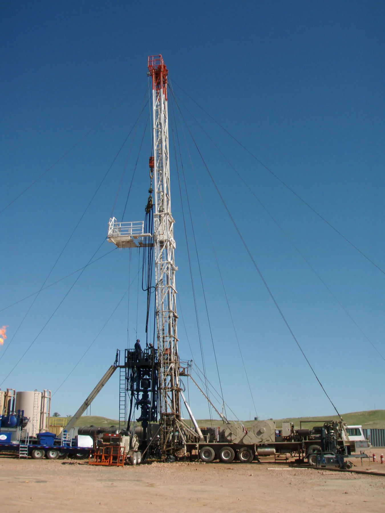

What wellbore cleanout must establish
The useful starting point is the new completion’s requirement. A tool must reach its destination through the actual restrictions along the route. Equipment that contacts the casing also depends on the condition of its intended setting area. DeGeare illustrates this distinction in a sidetracking application: his discussion addresses casing-wall preparation for a whipstock packer or anchor, then describes gauging in a particular wireline-packer arrangement. That application explains why passage and wall condition both matter; its specified tool sequence is not a universal recompletion program. [1, printed p. 123; PDF p. 118]
The same distinction helps frame a recompletion review. “The tool reached depth,” “the wall was mechanically cleaned,” and “solids were recovered” are separate statements. Each needs its own supporting record. Combining them into a single word such as “clean” can conceal an untested requirement.
A wellbore cleanout therefore needs a defined scope: the accessible route, the equipment-contact intervals, the debris expected from the work history, and the evidence required for the next installation. The overview of production packers and completion arrangements provides useful equipment context. Passing a cleanout review does not itself demonstrate a packer’s subsequent sealing performance or the pressure integrity of the well.
For a useful handover, place those requirements on the same drawing. Identify the components retained in the well, the route the new assembly must traverse, and the intended casing-contact interval. Relate the gauge record to that drawing using the stated depth reference. This prevents a wellbore cleanout result for one accessible section from being used to support an installation requirement in another. It is a way of defining the claim being assessed, not an additional tool-running instruction.
Where the debris comes from
Material inherited from the existing well
Start with what was already present. The Baker Hughes catalog identifies mud or cement sheath, rust, mill scale, paraffin, and similar casing-wall material among the targets of mechanical cleaning. DeGeare also notes that old wells and some mud-system histories can leave an unclean casing wall. These are candidate sources to investigate, not a diagnosis made from well age alone. [2, p. 114] [1, printed p. 123; PDF p. 118]
The distinction between attached and loose material is important. An adherent layer can remain outside an open central passage. Removing part of it can create fragments that still need to be transported or captured. A record of circulation does not, by itself, document either the original layer or the condition of the wall beneath it.
Material generated or released during intervention
Review the work already performed. The catalog names window cutting, packer milling, and junk milling as sources of ferrous debris. It separately addresses perforation burrs and other material remaining inside casing after perforating. These have different origins and may require different attention from a soft residue coating. The broader oilfield fishing-tool guide describes the surrounding tool families; here the question is what those activities leave for the next completion. [2, pp. 119, 134]
Cement work can also change the debris problem. Coiled Tubing Solutions describes cement nodes at squeezed perforations and excess cement that hardens before removal. It discusses scale and hard fill that cannot be removed by jet washing in the described applications. A previously passable interval can therefore require a fresh assessment after intervention. [3, printed p. 5; PDF p. 7]
Include the upper equipment in the history. The fishing catalog describes falling debris released during riser, BOP, and wellhead cleaning, including particles that are not circulated out. That is a conditional source wherever those operations and components apply. It explains why a review limited to the bottom of the well can miss material introduced from above. [2, p. 153]
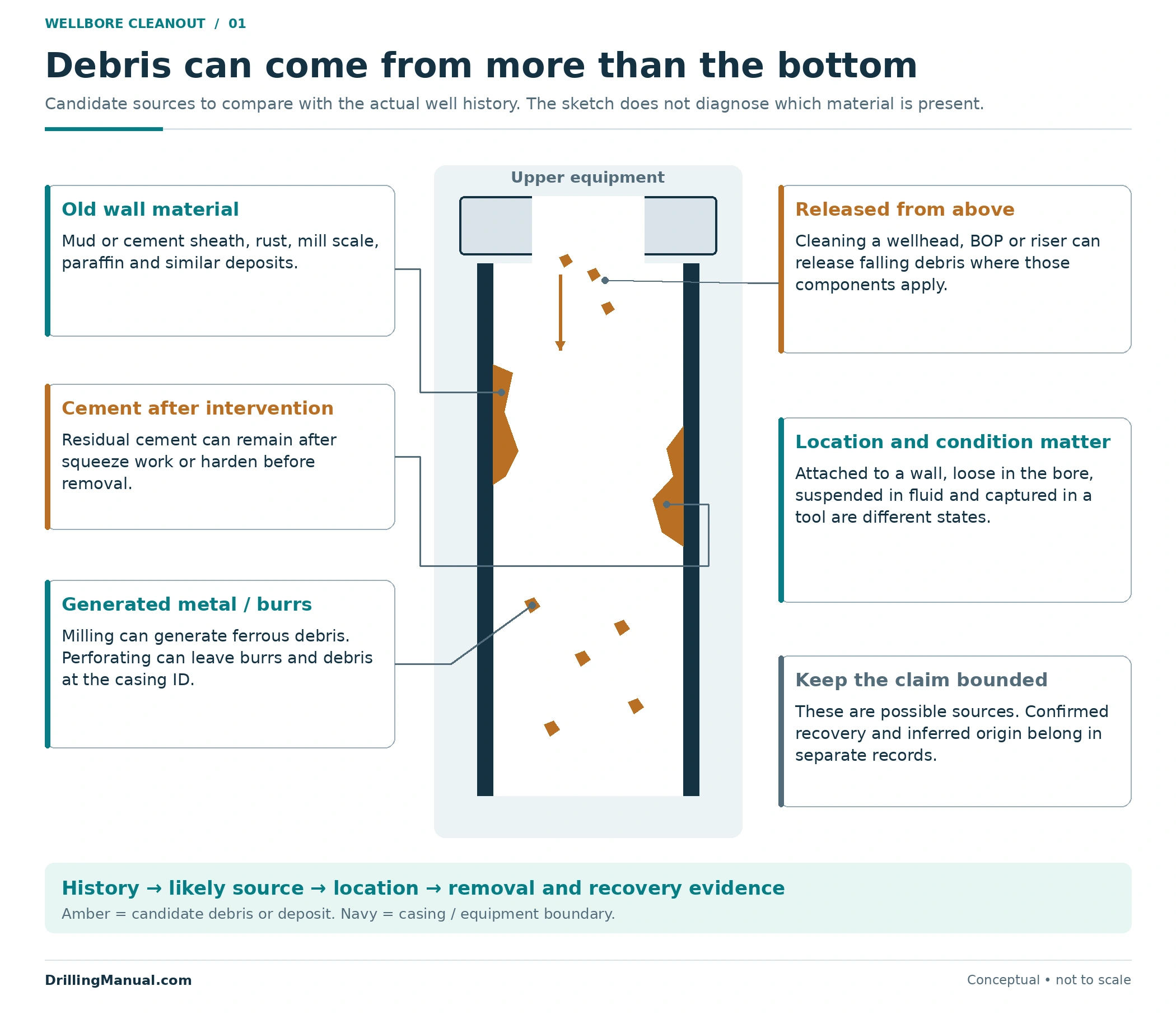
For wellbore cleanout planning, record the likely material, its possible location, and the operation that could have generated or released it. Keep confirmed recovery separate from inference. Metal collected after milling is useful evidence of recovered material; its presence does not quantify every fragment still downhole.
A chronological wellbore cleanout history is more informative than a list of tools. Separate material expected before intervention from material generated during the current work. Then connect each recovery observation to the relevant operation and interval. Unexpected contents deserve explanation, but appearance alone should not be presented as proof of a particular component’s failure. The record can state what was observed, what source is plausible, and what remains uncertain without inventing a diagnosis.
Four different jobs within wellbore cleanout
Scraping, gauging, transport, and capture answer different questions. A combined assembly may perform several functions, but combining hardware does not make the evidence interchangeable. The supplied catalog presents modular cleaning systems containing scrapers, brushes, circulation tools, magnets, filters, and baskets. Their selection depends on the application. [2, pp. 111, 114, 138]
| Function | What it acts on or demonstrates | What the observation does not establish alone |
|---|---|---|
| Scraping or brushing | Mechanical contact with accessible casing-wall material. | That all released material has left the well. |
| Gauging or drifting | Passage of a specified test body over a documented route. | Cleanliness of every wall surface or passage of a different assembly. |
| Circulating or displacing | Fluid movement through the actual connected path, with transport where conditions allow. | Removal of attached material or particles that cannot reach the observed return stream. |
| Capturing debris | Retention and recovery of material accessible to the chosen device. | A complete inventory of everything remaining outside that device’s reach or capability. |
This comparison is an evidence framework derived from the different functions, not a prescribed four-step operation. Scraper contact is useful only over the area actually treated. Gauge evidence needs the test dimensions and reached depth. Capture evidence needs the recovered contents and the recovery method’s limitations.

For example, a downhole magnet targets ferrous debris. It cannot establish the absence of cement simply because little magnetic material is recovered. The magnetic fishing-tool guide provides related equipment context. The material-specific limit follows from the magnet’s stated recovery purpose. [2, p. 134]
Likewise, a basket can recover material that circulating fluid cannot carry to surface. Coiled Tubing Solutions identifies this application for high-density debris and discusses collection capacity. An empty catcher, a full catcher, and clean surface returns are different observations; none should be translated automatically into “nothing remains.” See the separate junk-basket overview for the range of tool types. [3, printed p. 4; PDF p. 6]
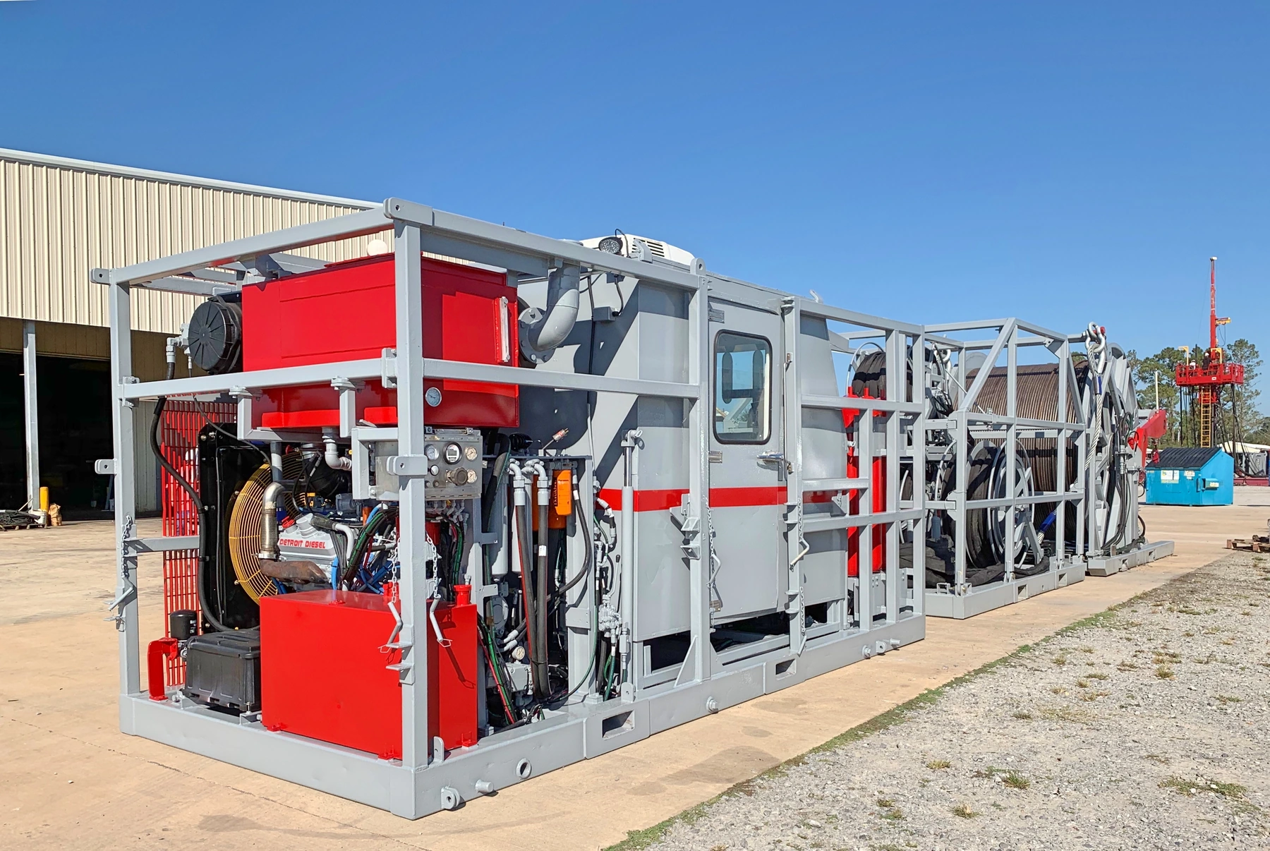

Follow the wellbore cleanout circulation path
A meaningful return observation starts with a traced fluid path. Identify where fluid enters, where it leaves the workstring, the annular or internal route it follows, and where it is observed at surface. A connection that diverts flow above the interval of interest changes what the returning fluid can represent. The catalog’s displacement-planning discussion explicitly includes forward and reverse circulation, bypass paths, well geometry, and pipe eccentricity. [2, p. 172]
The original diagram below compares two simplified routes. In one, fluid exits at an open lower end and returns through the illustrated annulus. In the other, a side outlet above a closed lower workstring section provides the depicted route. Returns from that second path do not demonstrate circulation through the interval below the outlet. These are topology examples, not recommended configurations or predictions of cleaning efficiency.
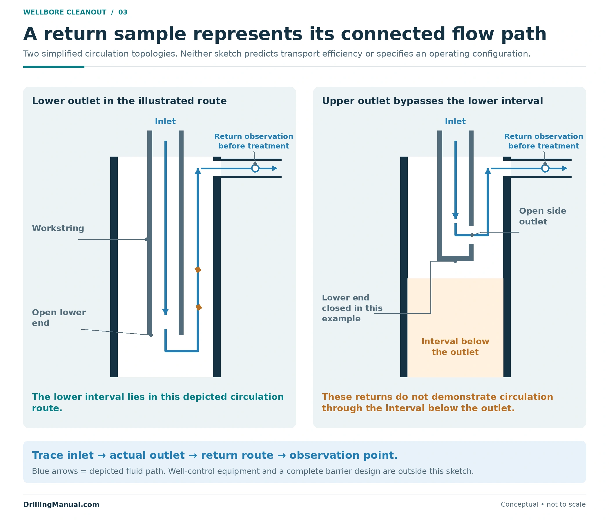
Even when the intended interval is in the circulation path, transport remains a separate question. The handbook describes circumstances in which the available annular carrying capability is insufficient to bring debris to surface. A clear sample can coexist with heavy material remaining downhole, material retained in a recovery tool, or a coating that has not entered the stream. That conclusion follows from the limits of the observation. [3, printed p. 4; PDF p. 6]
Specify what “clean returns” means in the job record: the sampling point, the relevant operating condition, the observation or measurement, and its approved acceptance criterion. The separate completion and workover fluid-testing article covers fluid tests. A fluid-quality result complements the bore and debris records; it does not replace them.
Sample location is especially important when a wellbore cleanout system includes filtration or capture. A sample taken after a filter describes the fluid after that treatment. It cannot be treated as an unfiltered record of everything arriving from the well. Record the position relative to solids-removal equipment and retain the recovered-material observations alongside the fluid results. This is a measurement-location distinction derived from the source’s separate filtering and recovery functions. [2, p. 138]

A passable bore can still contain a residual sheath
One of the clearest examples in the supplied books concerns a restricted entry into a larger bore. Coiled Tubing Solutions explains that a mill limited by the tubing’s internal drift can leave material against the larger liner wall. The resulting central passage does not necessarily expose the liner’s full inside surface. The book warns that the remaining sheath can later dislodge and contribute to stuck tools. [3, printed p. 5; PDF p. 7]
This is a geometry problem as well as a removal problem. The cleaning tool’s ability to enter a restriction and its ability to reach the intended wall are separate requirements. The source discusses an underreamer that passes a restriction, opens below it, and closes for retrieval; that description explains one tool principle, not a recommendation for every well.
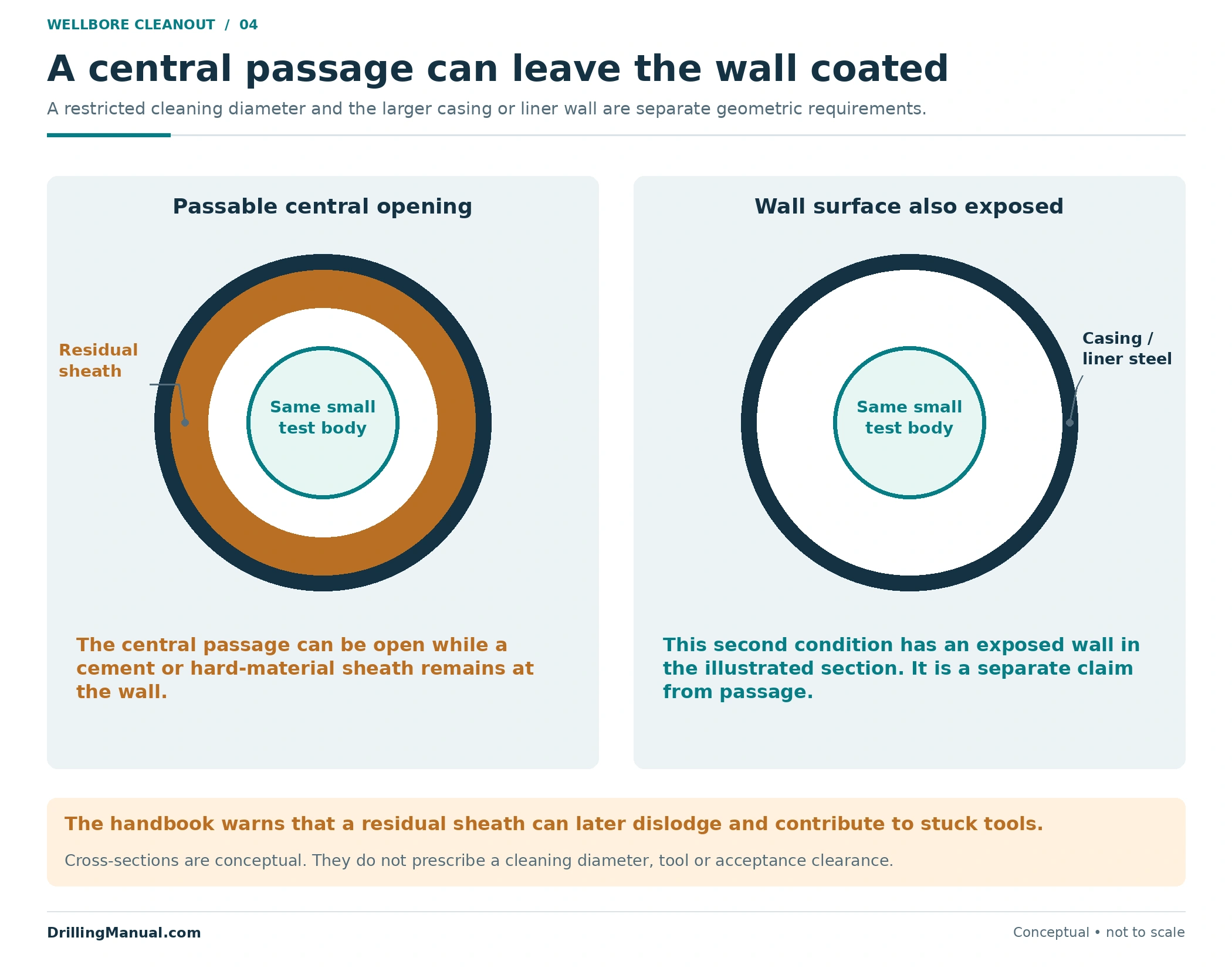
In wellbore cleanout, the practical question is which surface the next equipment needs. A central opening may permit a small tool to pass while leaving a planned casing-contact interval untreated. Conversely, treating that interval does not automatically establish that the entire access route is adequate. Keep both requirements on the same as-built schematic. The coiled-tubing guide provides conveyance context without changing these geometric distinctions.
What a successful gauge run actually confirms
The gauge record should identify the body that passed, its relevant dimensions, the reached depth, and the route. “Drift passed” without that information is difficult to relate to a new completion. DeGeare’s application ties gauging to a specific packer-setting objective; it does not say that any successful gauge certifies any later assembly. [1, printed p. 123; PDF p. 118]
Consider an original, deliberately simple example. Assume a known, circular residual opening of 146 mm. A rigid 144 mm gauge and a proposed assembly whose largest running OD is 148 mm are considered separately, coaxial with that opening. The numbers are invented and are not casing specifications.
| Body | Outside diameter | Opening minus body diameter | Idealized geometric conclusion |
|---|---|---|---|
| Test gauge | 144 mm | +2 mm | Smaller than the assumed opening. |
| Entire proposed assembly, maximum running OD | 148 mm | −2 mm | Too large for that assumed opening. |
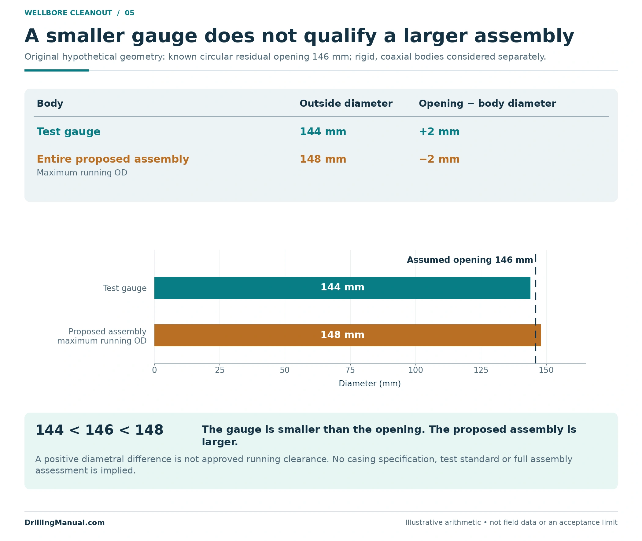
The example demonstrates why gauge selection must relate to the installation objective. A positive diameter difference is not approved running clearance. Actual acceptance must address the relevant assembly geometry and route. Nor does passage measure wall thickness, pressure integrity, or the condition of a surface outside the gauge’s swept envelope. These are limits of a dimensional observation, not additional claims made by the gauge.
Tie wellbore cleanout acceptance to the new completion
A useful readiness statement names the requirement, the evidence, and any remaining gap. For the access route, it might refer to a documented gauge body and reached depth. For the intended casing-contact interval, it might refer to the cleaning coverage and the relevant recovery record. For fluid condition, it should identify the representative observations required by the approved program. The source material supports the different functions; the combined review below is an original editorial framework. [1, printed p. 123; PDF p. 118] [2, pp. 111, 114, 138, 172]
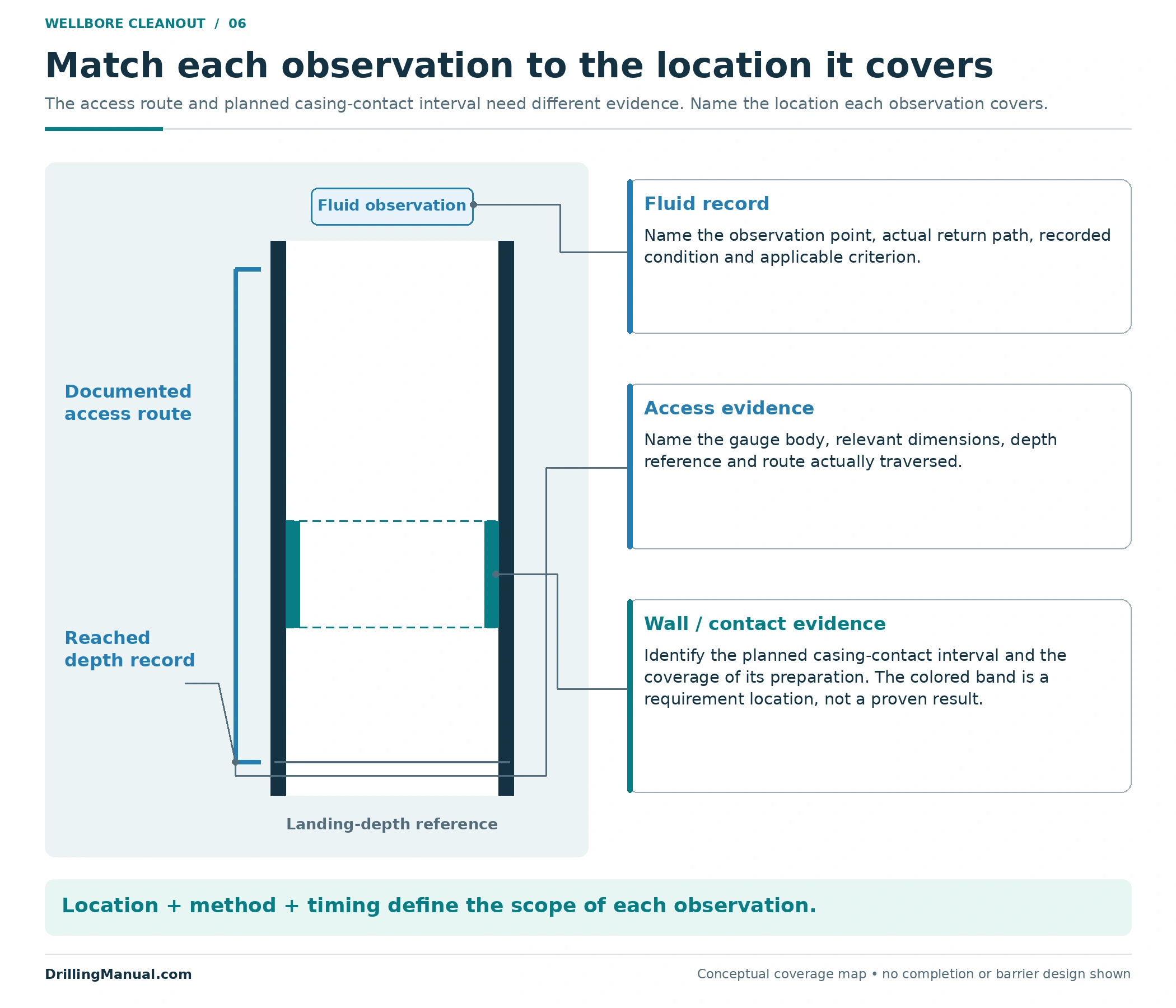
Keep the timing explicit. If milling or upper-equipment cleaning occurred after the last relevant evidence was collected, review what that later activity could have changed. The catalog identifies both operation-generated metal and falling debris from upper equipment. An earlier result remains a valid record of that earlier condition; it may no longer cover the current installation question. [2, pp. 134, 153]
Wellbore cleanout criteria should be agreed for the job and equipment, with defined measurement methods and responsibilities. The cited passages do not supply one universal turbidity number, circulation volume, gauge difference, or allowable recovered-debris mass for all recompletions. Importing such a number from an unrelated job would add precision without establishing applicability.
The wellbore cleanout record should also preserve the difference between “none observed” and “not checked.” An inspected recovery tool with no visible contents is a recorded observation; a tool whose contents were not documented supplies no equivalent evidence. Similarly, a recovered mass cannot establish a removal percentage unless the starting inventory is independently known on a comparable basis. The objective is a traceable installation decision, with the remaining uncertainty stated plainly, rather than a percentage or pass label unsupported by the available observations.
A hypothetical wellbore cleanout review
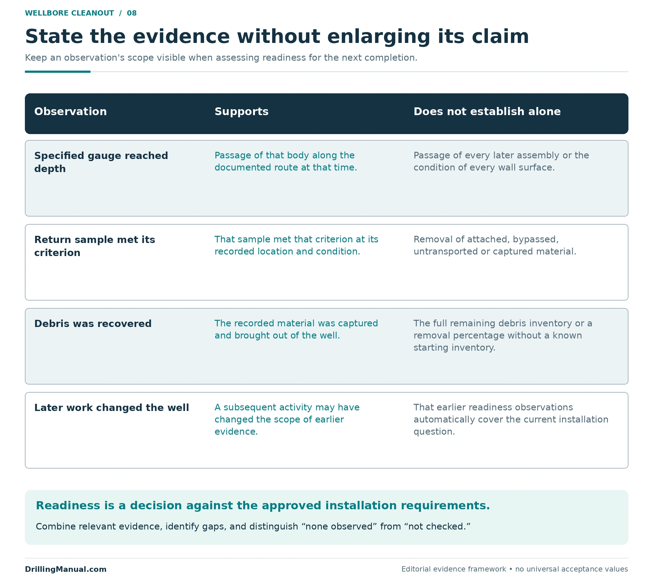
Suppose a recompletion record contains four observations: a gauge reached the planned landing depth, returns met the documented fluid criterion, a recovery tool contained metal fragments, and milling subsequently took place above the planned setting interval. This is an invented teaching case, not field data. None of those observations should be discarded, but their scope must be reconciled.
| Recorded observation | Useful conclusion | Question still requiring closure |
|---|---|---|
| Specified gauge reached the stated depth. | That body traversed that route at that time. | Does it represent the new assembly, and is the route unchanged? |
| Sample met the agreed fluid criterion. | The recorded sample met that particular criterion. | Was its location and circulation path representative of the required interval? |
| Metal was recovered in a tool. | That material was captured and brought out. | How does it relate to expected debris and the tool’s recovery coverage? |
| Later milling was recorded. | A subsequent debris-generating activity occurred. | Which readiness evidence needs updating before installation? |
The correct conclusion is not an automatic pass or failure. It is a bounded decision against the actual acceptance requirements. The value of the review is that it exposes the missing connection between an observation and the requirement it is supposed to satisfy. It also keeps installation readiness separate from later functional verification of the completed well.
Wellbore cleanout FAQs
Do clear returns prove the casing is clean?
No. They describe the observed return stream. Material may remain attached to the wall, may not be transported to surface, or may have been captured downhole. The fluid observation needs to be combined with the relevant wall, passage, and recovery evidence. [2, pp. 114, 138] [3, printed pp. 4–5; PDF pp. 6–7]
Are a scraper run and a gauge run equivalent?
No. Mechanical cleaning acts on wall material; gauging demonstrates passage of the specified body. An assembly can combine functions, but its record should still distinguish treated coverage from demonstrated passage. [1, printed p. 123; PDF p. 118]
Why recover debris downhole instead of relying on circulation?
The handbook describes particles too heavy for the available annular transport conditions. A suitable capture system offers another recovery route. Its applicability and capacity remain job-specific. [3, printed p. 4; PDF p. 6]
Does a clean magnet prove all debris is gone?
No. The described magnet targets ferrous material. Its result cannot establish the absence of cement or other material outside that recovery mechanism. It also needs to be interpreted within the area and conditions actually covered. [2, p. 134]
Can a small gauge pass through a coated bore?
Yes, where the remaining opening accommodates it. The source’s residual-sheath example demonstrates why a central passage and an exposed casing or liner wall are different conditions. [3, printed p. 5; PDF p. 7]
What is the universal cleanout acceptance limit?
The cited material provides none. Acceptance should match the approved installation requirements, debris risks, route, and observation methods. A defensible record states what was demonstrated and which uncertainties were resolved, rather than relying on a single “clean” label.
Book references
- Joe DeGeare. The Guide to Oilwell Fishing Operations: Tools, Techniques, and Rules of Thumb. Second edition. Gulf Professional Publishing, an imprint of Elsevier, 2015. ISBN 978-0-12-420004-3. Chapter 16, printed pp. 122–123; supplied PDF pp. 117–118. The casing-cleanliness passage is printed p. 123.
- Baker Hughes. Fishing Services Catalog. Copyright 2013. Printed and supplied PDF pp. 2, 111, 114, 119, 134, 138, 153, 172. Product examples support mechanism and scope explanations; their operating settings and commercial performance claims are not adopted as general criteria.
- Baker Oil Tools / Baker Hughes. Coiled Tubing Solutions: Solve Downhole Problems With Reliable, Cost-Effective Technology. Copyright 2003. Publication BOT-02-9242, 07/03. “Debris Catching” and “Underreaming,” printed pp. 4–5; supplied PDF pp. 6–7.