The service life of drill lines is greatly improved by drawing up a cut and slip program based on service increments. The main requirement for any program is to have an excess of drill line above that required for string-up. This excess can be slipped through the system at such a rate that wear is evenly distributed so that the line cut off at the drum end has just reached the end of its useful life.
Slipping a new line into the system without cutting off the drum end only shifts the critical wear points on the sheaves but does not affect the cross-over points on the drum. For this, the wire has to be cut; cutting prevents too much wire accumulation on the drum and ensures that the critical points on the drum are shifted.
Drill Line Cut & Slip Program
The number of slips between cut-offs can vary from one or two slips up to as many as seven or eight. This depends on the cut-off length and circumstances involved, such as rough drilling and fishing jobs.
The length of the wire rope slipped should be sufficient to ensure that no part of the rope will be in a critical wear position for a second time. The cumulative length of feet slipped between cut-offs should equal the recommended cut-off length. For example, if 80 ft is cut off every 800 ton-miles, 20 ft could be slipped every 200 ton-miles, and the line cut off at the fourth slip.
Cut Off Length
The cut-off length is affected by various factors, such as:
- Load pick-up points at the top and bottom of the traveling block’s range of travel.
- Cross-over points on the drum and the size of the drum.
- Drill line size and quality.
- Service or safety factors apply to the area and job to be done.
In the slip and cut for drill line program, some oil and gas companies usually determine the cut-off length using the information in the Shell Well Engineers Notebook.
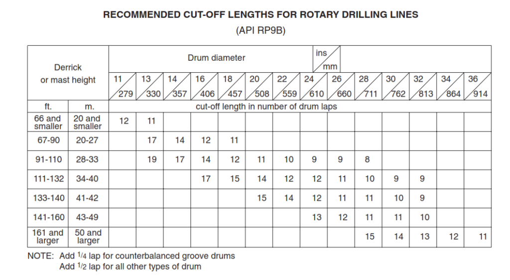
The above table gives the number of laps to be cut concerning the derrick height (m or ft) and the drum diameter (mm or in). It also gives information about an extra lap to be cut: typically 1/4 lap for counterbalanced grooved drums and 1/2 lap for all other types of drums. This ensures the wire rope’s cross-over points lie in another place after each cut.
Conversion Of Drum Laps To Cut-Off Length
To ensure a change of the point of drum crossover, where the wear and crushing are very severe, either 1/4 or 1/2 lap should be added to the number of laps listed on table 1.
- Add 1/4 lap for counterbalanced groove drums.
- Add 1/2 lap for all other types of drums.
Conversion of laps to length is simply:
Cut-off length = π x d x no. of laps
EXAMPLE: What is the recommended number of laps and cut-off length for the block line for slip & cut drill line on a rig with a derrick of 138 ft (42m) and a drum of 30″ (762 mm) diameter? The drum is counterbalanced.
From the above table:
The number of laps = 10 + 1/4
- In field units: Cut-off length = π x 30/12 x 10 1/4 = 80.5 ft
- In S.l. units: Cut-off length = π x 0.762 x 10 1/4 = 24.5 m
Safety Factor
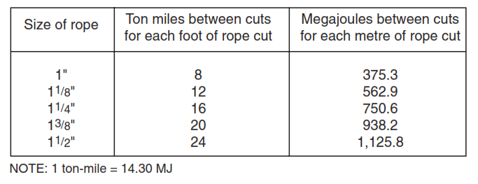
Work Per Unit Length Cut When Safety Factor Of 5
The below table shows the megaJoule per meter cut or ton-miles per foot cut operating with SF 5.
When Safety Factor Is Other Than “5”
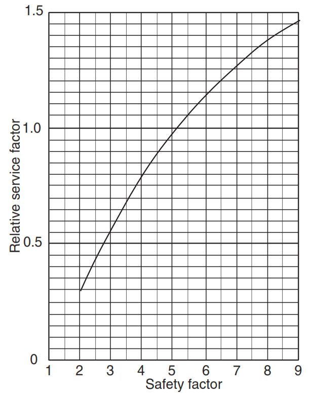
Safety Factors will undoubtedly be other than 5 for most operations. The block line work should therefore be adjusted by the relative service factor.
Note: adjustments should only be made to the drilling block line work. Given the high variations in the safety factors during casing and round trips, block line work during these operations should be calculated on a safety factor “5”.
The below graph is used to determine the relationship between the safety (design) factor and the kdaN-km or ton-mile service factor. From the graph below, obtain the RELATIVE SERVICE FACTOR. The calculated work must be divided by this factor to obtain the ADJUSTED WORK.
Preparation For The Slip & Cut Operations
- Drill String should be positioned at bottom of last casing string and well secured.
- Ensure that well bore is static.
- Start setting slips (with drill string at proper height).
- After blocks are lowered, unlatch the elevators.
- Drilling Crew shall inspect drilling line, while Driller is raising blocks.
- After blocks are raised to the proper position, install a safety valve. Tighten the drill pipe safety valve to the proper makeup torque (do not put tongs on the open/close area of the drill pipe safety valve).
- Move the blocks to the proper position for installation of block hanging line.
- Crew to assist Derrickman, in attaching harness / bosun’s chair to air / hydraulic hoist.
- Ensure tag line is attached to bosun’s chair.
- While lifting Derrickman up, use tag line to position Derrickman properly.
- While lowering Derrickman, use tag line to position Derrickman properly.
- Remove air / hydraulic winch from harness / bosun’s chair and store for later use.
- Start removal of Drawworks front guards.
- Remove automatic driller / weight indicator load cells off dead line.
- Remove secondary safety clamp and drilling line anchor clamp.
- Secure tag line to drilling line, use tag line to pull initial drilling line from drum. Assist in taping drilling line area being cut.
- Place drilling line in line cutter properly. Ensure drilling line is secured prior to cutting, to avoid any recoil in line.
Safe Procedure For Slip & Cut Drill Line
- Remove the excess worn line from the drum
- Start the cutoff as per plan. Note: Use the following as a protection
- Wireline cutter.
- Eye protection.
- Operate cutter from the proper side (closed/pump side)
- Pull drill line off drum and guide line out V-door / beaver slide.
- Rotate the drum forward to proper position for installation of drilling line clamp.
- Clamp the drum end of the line back into the drawworks drum.
- Start tightening the drum clamp as much as you can.
- Loosen the clamps on the wire line anchor.
- Keep proper tension on drilling line while spooling drilling line on drum.
- Slip through as much line as required to put the desired wraps on the drum.
- Make sure that the warps are tight and together.
- Tighten the wire line clamps on the anchor.
- Then, start to pick up the traveling block.
- Remove the hanging line(s) from block. We should tie back the hanging line(s) in the derrick corner out of the way of the blocks. In addition, we make it ready for the next slip & cut.
- Recheck all clamps and position of line and start in hole with a safe drilling line.
- Install the crown protection tool if it was removed. Adjust it as the company policy to stop the blocks as required.
- Reinstall the guard on the front of the rig drawworks.
- Reinstall the weight indicator sensor on the dead line.
- Remove the TIW valve.
Example For Drill Line Slip & Cut Calculations
A kdaN-km or ton-mile program consists of the following:
- Determine the length of the rope to be cut.
- Calculate kdaN-km or ton-miles between cuts.
- Determine the number of slips of the block line (at least two) between cuts.
Example
| Derrick | : | 43 m |
| Drum | : | Eight lines |
| Drill line | : | 34.9 mm 6×19 IPS IWRC |
| Traveling block | : | 8 lines |
| Hole depth | : | 4,100 m |
| Mud gradient | : | 18.83 kPa/m |
| API Drill pipe Specs | : | 127 mm – 19.5 lbs/ft, X95 with NC50 connections (average joint length is 9.45 m) |
| Drill collars | : | 183 m x 203.2 mm x 76.2 mm |
| Weight Block + Hook | : | 9,000 kg |
| Casing | : | 244.48 mm, 69.94 kg/m – N80/P110 (average joint length is 12.19 m) |
Calculate the :
- Safety factor when drilling at 4,100 m.
- Pipe set-back load.
- Length of cut.
- Work between trips at 3,800 m and 4,100 m.
- Drilling work 3,800 – 4,100 m.
- Casing work when run in at 4,100 m.
- Block line safety factor with the casing string at 4,100 m. Is any action needed?
Solution For Example – Slip & Cut Drill Line
Safety factor when drilling at 4,100 m
String weight in air = DP weight in air + DC weight in air
| DP weight in air | = | (4100 – 183) x 31.9 x 9.81 x 10-3 | = | 1,225.8 kN |
| DP weight in air | = | 183 x 218.8 x 9.81 x 10-3 | = | 392.8 kN |
| Total weight in air (set-back load) | = | 1618.6 x 0.756 | = | 1,618.6 kN |
| Buoyancy factor (BF) | = | 0.756 | ||
| String weight in mud | = | 1,223 kN | ||
| Hook load | = = | string weight in mud + weight of block plus hook 1,223 + (9,000 x 9.81 x 10-3) | = | 1,312 kN |
| Fast line tension | = = | Hook Load / (Number Of Lines x Efficiency Factor) 1312 / (8 x 0.842) | = | 195 kN |
| Safety factor | = = | Breaking Strength Of The Rope / Fast Line Tesnion 743.7 / 135 | = | 3.81 |
Pipe set-back load:
The pipe set-back load is 1,618.6 kN
Length of cut (For Cut & Slip Drill Line)
The number of laps is 11 plus 1/4.
11.25 x π x 0.782= 26.93 m
For a safety factor of 5 and 34.9 mm (=1-3/8″) wire rope, the recommended work is 938.2 MJ per meter cut. That is 93.82 kdaN-km per meter cut-off.
Therefore 26.93 m should be cut off after accumulated work of 26.93 x 93.82 = 2526.6 kdaN-km = say 2527 kdaN-km.
Work between trips at 3,800 m and 4,100 m:
Wm= 31.9 X 0.756 = 24.1 kg/m
C = (218.8 – 31.9) x 0.756 x 183 = 25,857 kg
M = 9,000 kg
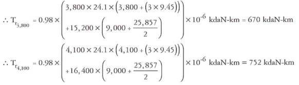
The work between trips = 752 – 670 = 82 kdaN-km
An average SF of 5 is normally assumed for round trip work. The actual SF varies considerably, because the load varies between the empty block and the full string weight.
Drilling work 3,800 – 4,100 m:
Td= 2 x ( Tr4,100 – Tr3,800) = 2 x 82 = 164 kdaN-km
While drilling (or coring) under continuous full load, and with a safety factor other than 5, the calculated work can be adjusted using the relevant service factor (Figure 1).
In this example the safety factor at 4,100 m is used i.e. 3.81 and the corresponding service factor is 0.76, so that:
Td = 164÷0.76 = 216 kdaN-km
Block line work done when casing is run at 4,100 m
Wc = 69.94 x 0.756 = 52.84 kg/m
Tc= (0.98÷2) x (4,100 X 52.84 X (4,100+12.19) + (16,400’9,000)) x 10-6 kdaN-km = 509 kdaN-km
Block line safety factor with the casing string at 4,100 m
Hook load = string weight in mud + weight of block plus hook
Hook load = ((69.94 X0.756)x4,100+9,000) x 9.81 x 10-3 kN = 2,215 kN
Fast line load = 2215 ÷ (8 X 0.842) = 328.8 kN
Safety Factor = 742.7 ÷ 328.8 = 2.26
This is too low (Shell requirement is SF of 2.5 for running casing For Cut & Slip Drill Line). The required action is therefore to re-string to ten lines and recheck the safety factor.
Fast line load with ten lines = 2215 ÷ (10 X 0.811) = 273.1 kN
Safety Factor = 742.7 ÷ 273.1 = 2.72 which is now acceptable
| Operation | Work done in kdaN-km | Slip + cut | Metres on reel | |||||
| This job | Cumulative | |||||||
| 1,178 | 1x | 612.53 | ||||||
| Trip at 3,800 m | 671 | 1,849 | 2x | 612.53 | ||||
| Drill to 4,100 m | 216 | 2,065 | – | 612.53 | ||||
| Trip at 4,100 m | 753 | 2,527 + 291 | 26.93 m | 585.60 | ||||
| Casing at 4,100 m | 509 | 800 | – | 585.60 | ||||
Hi, thanks for the article!
I want to ask whats the meaning of cross-over point in drawworks?