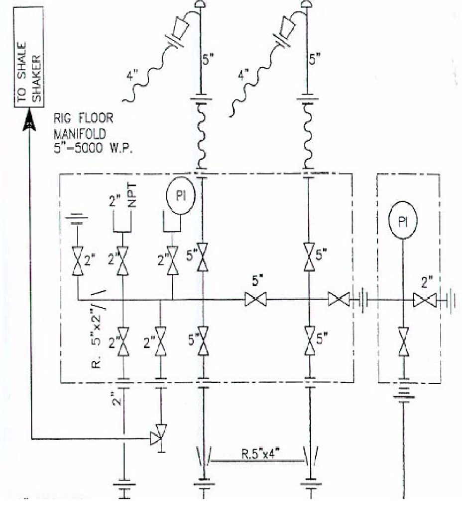
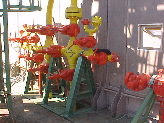
The standpipe manifold is one of the drilling rig components on the rig floor. From here, the driller can line up the mud pumps to the top drive system or the drilling kelly. This is also where we can fit the manifold gauges showing the driller’s mud or the standpipe pressure.
It is essential to inspect the standpipe manifold during the rig acceptance. In addition, testing the standpipe valves should be to the full working pressure for at least 10 mins.
There are two types of standpipe manifolds:
- Single Standpipe
- Dual Standpipe
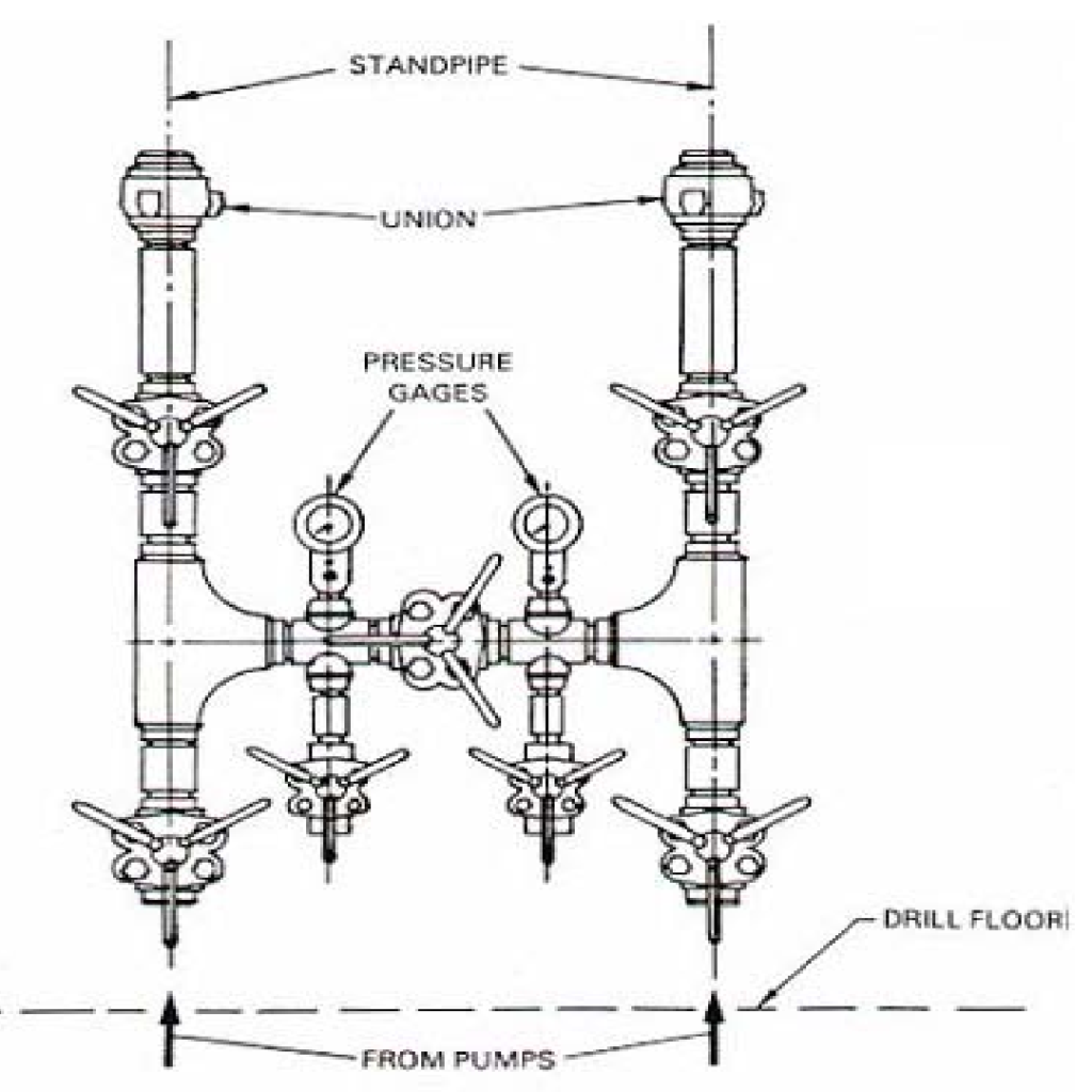
Standpipe manifold n : a series of lines, gauges and valves used for routing mud from the pumps to the standpipe.
Heriot Watt University- Drilling Engineering Book
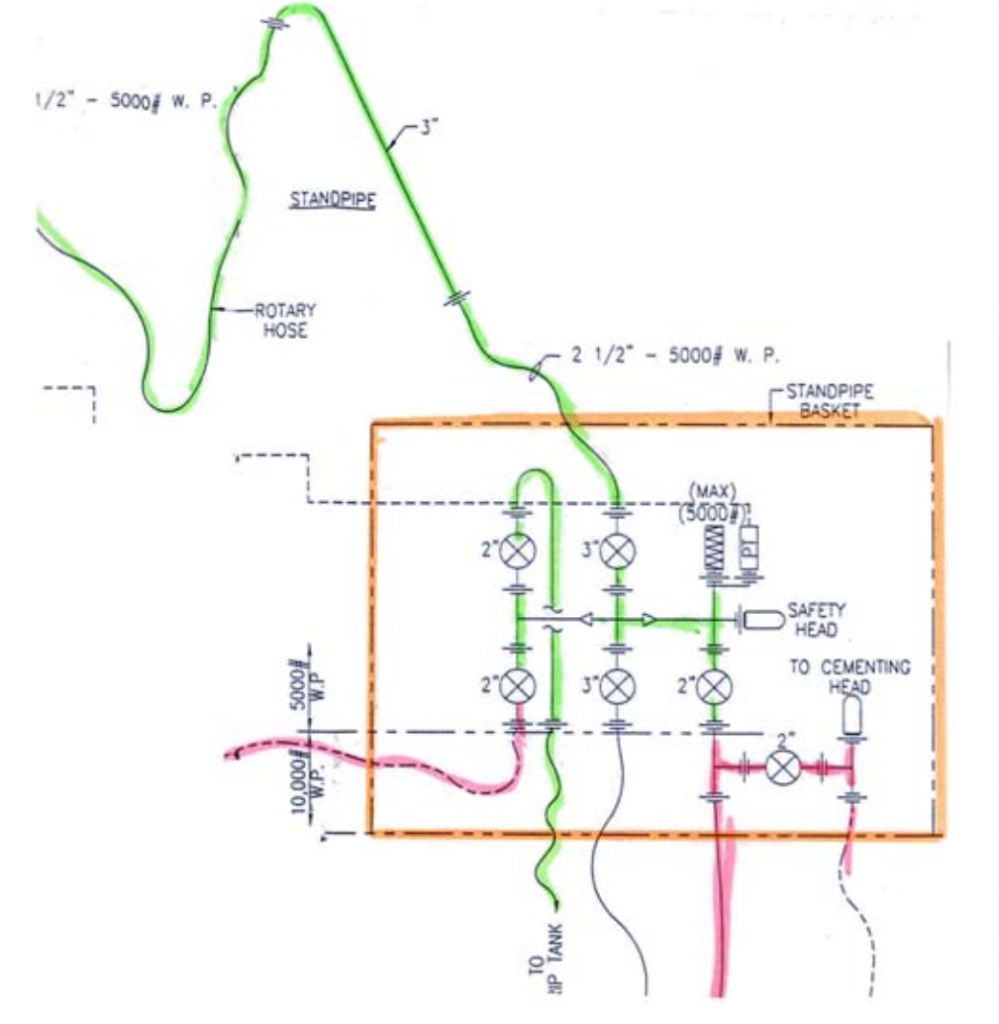
We could line up such a manifold to provide communication to pump any fluid mud or cement in either drill pipe or annulus through the choke manifold or by passing it.
Components:
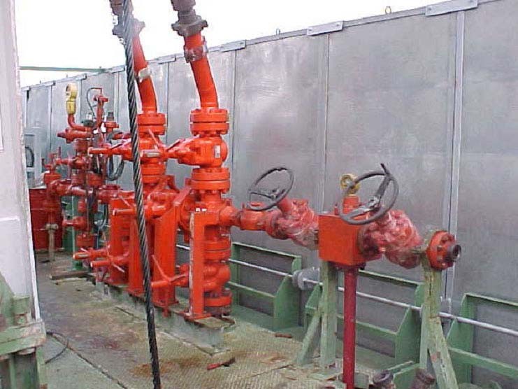
The standpipe manifold is composed of pipes and valves. It connects the high-pressure mud pumps to the injection head to circulate the drilling mud down the DP. There are several outlets on the mud manifold to connect the pressure transducer. This allows the crew to monitor the “standpipe pressure.”
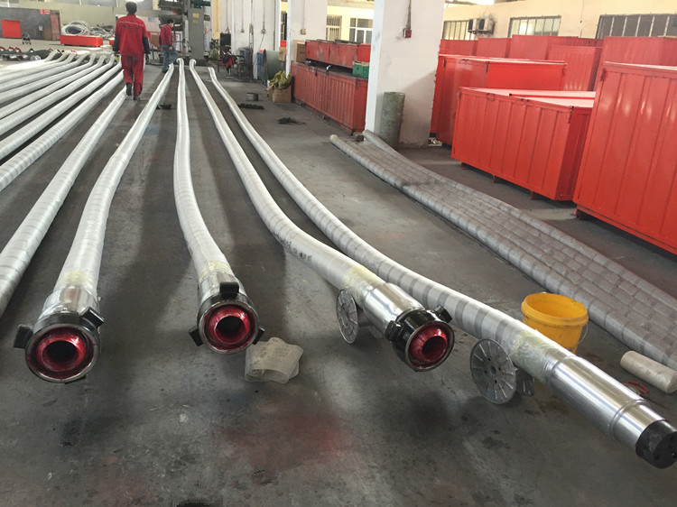
Rotary Hose and Vibrator Hose
The rotary drilling hose (API7K) is the flexible connector between the top of the standpipe and the swivel that allows for vertical travel. Its lengths are in the range of 45 ft (13.7 m) and over.
We generally use rotary vibrator hoses as flexible connectors between the mud pump manifold and the standpipe manifold to accommodate alignment and isolate vibration. Its common lengths are 30 ft (9.2 m) or less.
Mud Valve In Standpipe Manifold
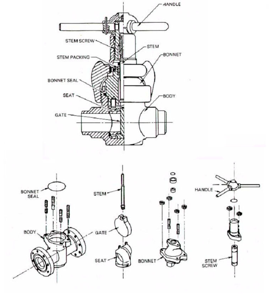
A gate valve uses a closing mechanism different than a ball valve. There is a blank plate across the flow path in the gate valve to halt the fluid flow. When we open the valve, the plate moves so that a section of the plate containing an orifice will be across the flow path, which thus allows fluid movement through the orifice. The gate and seat are easily changeable for redressing.
The valve dimension should be proportional to the flux speed. 20 ft/s (6 m/s) to limit the wear. The valve connections could be flanged, welded, or threaded. API rules are against threaded connections since 2″ 5000 psi w.p. Nominal dimensions refer to the nominal gauge of the line connected to the valve. The most common sizes are 2 -3- 4- 5 -6 inches. Also, working pressures are 1,000, 2,000, 3,000, 5,000, 7,500 psi.
Quick Unions
Generally, quick unions are used in oilfields to connect hoses and lines. There are many types of them. The below figure shows the red nut blue sub, which is used in connecting hoses of the standpipe manifold.
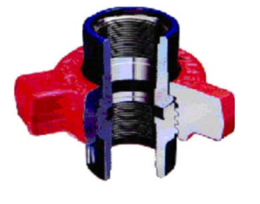
These unions are available in 1 through 4-inch 10,000-psi and five and 6-inch 7,500-psi NSCWP. These unions also have a resilient nitrite seal ring (5-inch and 6-inch have nitrile o-rings). They are made from alloy steel and are used primarily by service companies in cementing, fracturing, and acidizing applications. Designed for high-pressure systems, including truck-mounted systems, Fig. 1002 unions are also available as non-pressure seal unions and in butt-welds. Other types are such as Figure 1002, Figure 1202, etc…
Pressure Readings For Standpipe Mud Manifold
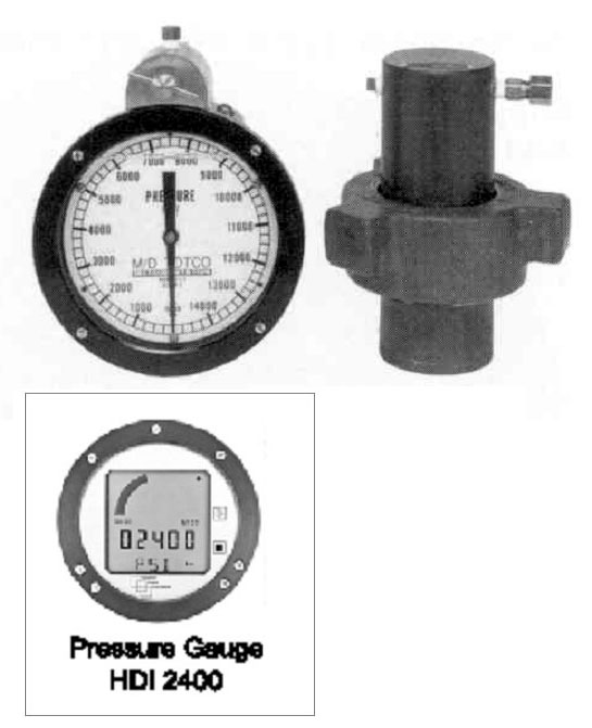
We usually use pressure gauges or transducers for the pressure reading in the standpipe manifold. Transducers provide a quick, accurate check on mud pump operation and help detect washout problems in drill pipe or drilling bit nozzle problems.
References:
- Eni Rig Book
- The Wee Land Rig Drilling Handbook