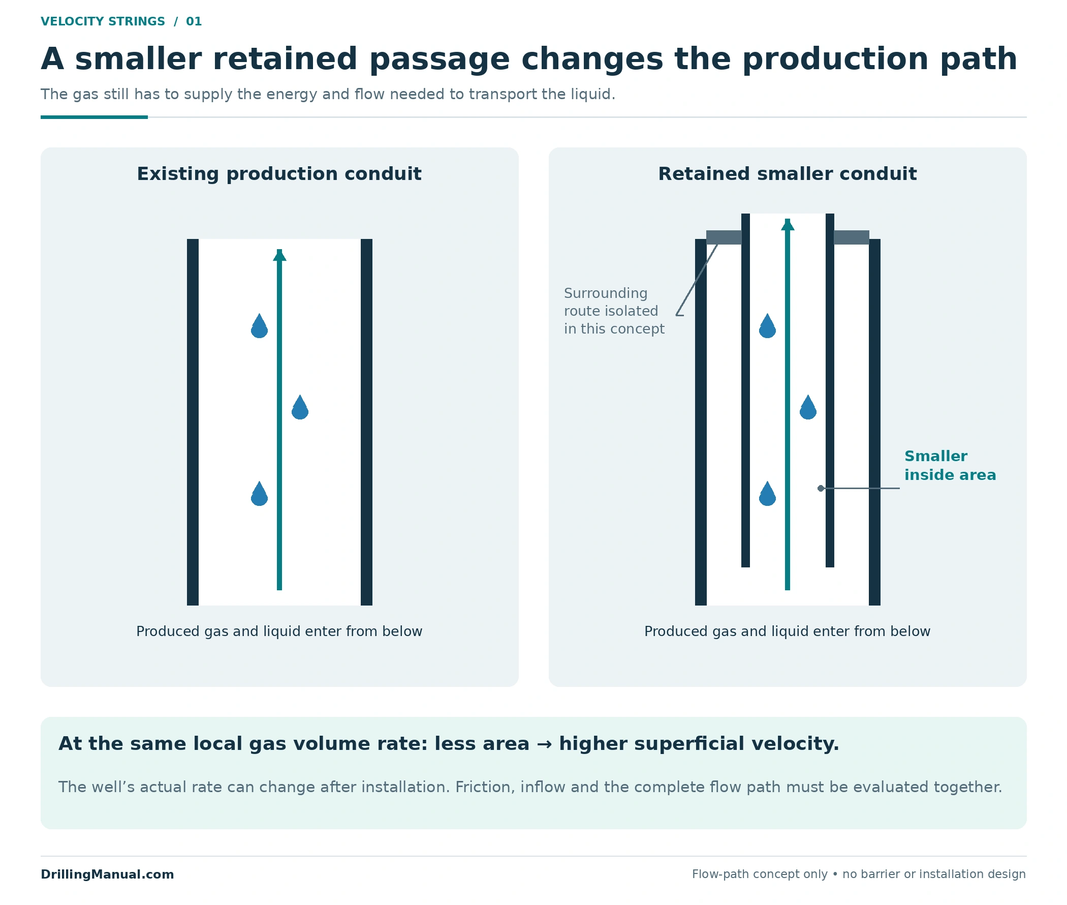
A velocity string gives produced gas a smaller passage through which to carry liquid. That can help a loaded gas well, but the smaller passage also adds friction. The useful question is therefore whether the completed well can deliver enough gas through the proposed conduit to transport its liquids under the conditions expected after installation. The smallest tube does not automatically give the best result. [1, pp. 10-31–10-34]
This article assumes that the liquid-loading problem has already been investigated. Its focus is the retained flow path: what changes when the conduit becomes smaller, how to compare alternatives and which completion functions the installation must preserve. It does not provide a tubing-size recommendation or an installation sequence.
What Does a Velocity String Change?
A velocity string is a smaller production conduit retained in the well to improve liquid transport. Coiled tubing is one way to provide that conduit inside an existing completion; the important hydraulic change is the usable flow area. A smaller area gives a higher average gas velocity at the same local gas volume rate. The production rate that the reservoir and completion can sustain must then be evaluated separately. [1, p. 10-31] [2, pp. 5–7]
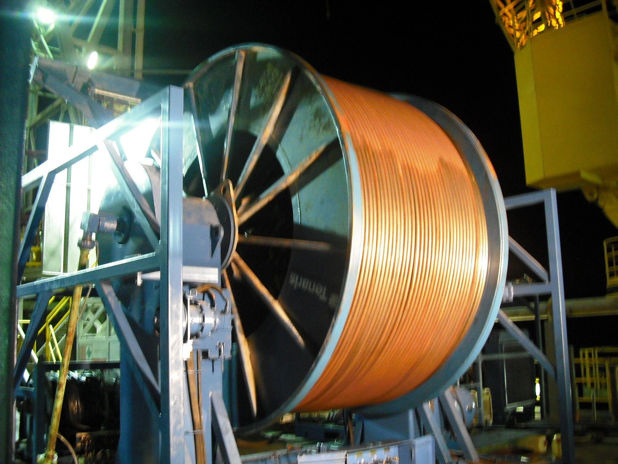
The distinction between a retained completion and a temporary intervention matters. A coiled-tubing unit can convey equipment or deliver fluids during a service job. Leaving a string as a production conduit changes the well’s continuing flow arrangement. The coiled tubing guide covers the broader equipment and applications; here, the string’s production duty governs the comparison. [1, pp. 13-3–13-4]

Velocity String Area: A Useful Calculation with a Boundary
For an ideal round, unobstructed bore, area is A = πD²/4. The local superficial gas velocity is jg = Qg,local/A: the actual gas volume rate at the point being considered divided by the conduit area. “Superficial” means that gas volume is divided by the whole flow area; it does not assert that gas occupies every part of a multiphase cross-section. This geometry explains the area effect, while the manuals’ transport discussion supplies the hydraulic context. [1, pp. 10-31–10-33] [2, pp. 7–8]
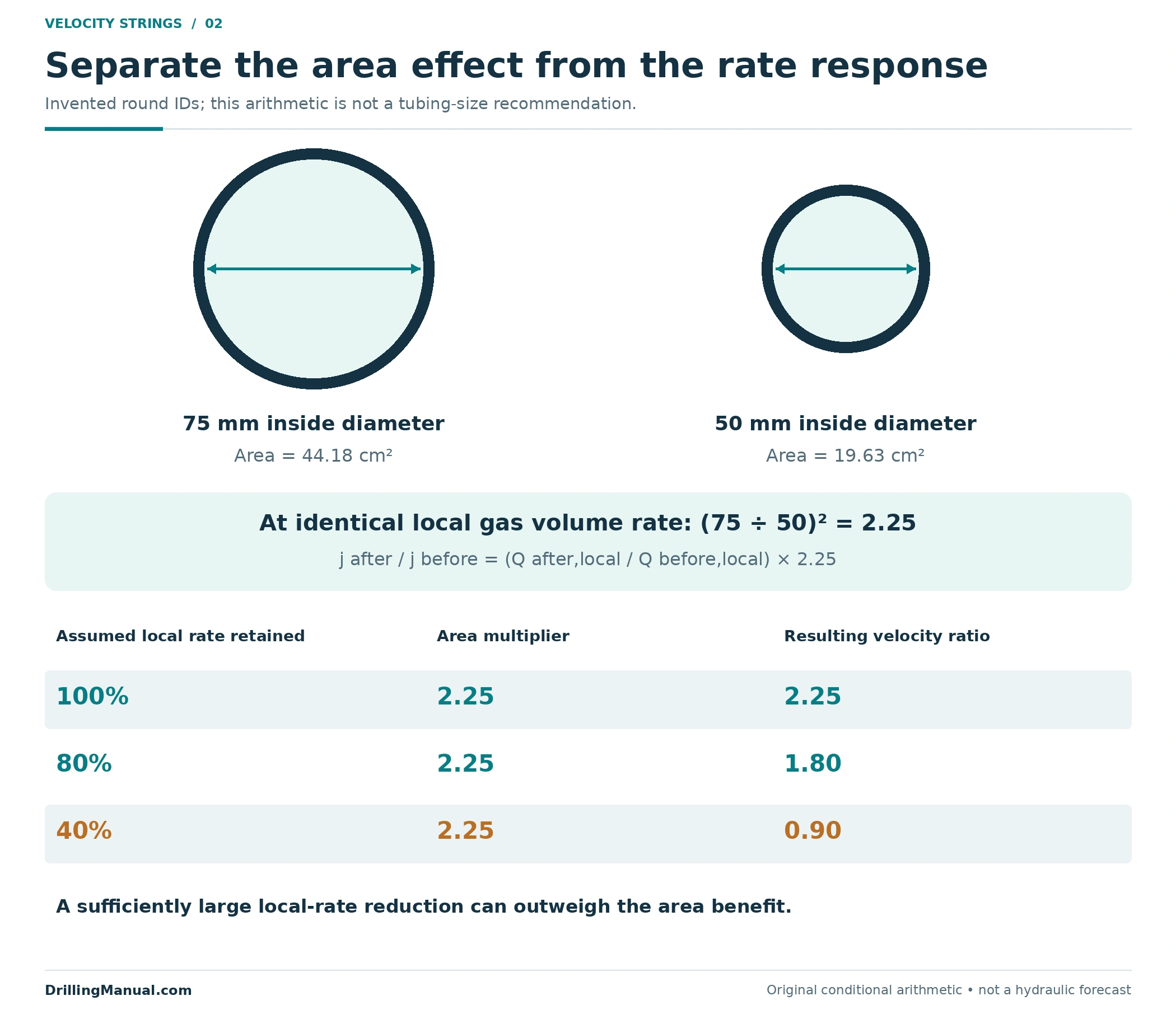
Consider two invented internal diameters, 75 mm and 50 mm. They are teaching values, not proposed field sizes. Their areas are approximately 44.18 and 19.63 cm². At an identical local gas volume rate, the smaller bore gives a velocity ratio of (75/50)² = 2.25. This calculation holds the local volume rate constant; it does not predict that the well will maintain its previous rate after the completion changes.
| Assumed local gas volume rate after the change | Area effect | Resulting velocity ratio | Meaning of this arithmetic |
|---|---|---|---|
| 100% of the previous local rate | 2.25 | 2.25 | The pure area comparison. |
| 80% of the previous local rate | 2.25 | 1.80 | A smaller rate still gives a higher local velocity in this assumed case. |
| 40% of the previous local rate | 2.25 | 0.90 | A sufficiently large rate reduction can outweigh the area change. |
The general ratio is jafter/jbefore = (Qafter,local/Qbefore,local) × (Dbefore/Dafter)². The three assumed rate ratios show why a velocity string needs a coupled performance assessment. They are not forecasts, transport thresholds or approval criteria.
A further boundary is the location of the comparison. The same standard gas rate does not occupy the same volume at every pressure and temperature along a well. Gas density and the fluid properties used in a transport model change with those conditions. Consequently, the velocity string assessment must connect its rate basis to the depth being evaluated. A surface-rate label attached to an otherwise unexplained velocity calculation is insufficient. [1, pp. 10-32–10-33]
Likewise, an area ratio says nothing by itself about the liquid film, droplets or phase slip. The source manuals discuss liquid-transport mechanisms and multiphase regimes separately from conduit geometry. The illustrated 2.25 ratio is therefore useful for explaining the first effect of changing diameter, but it cannot replace a suitable transport model for the actual trajectory and fluid system. [1, p. 10-32] [2, pp. 7–8]
Why Smaller Tubing Can Help and Hurt
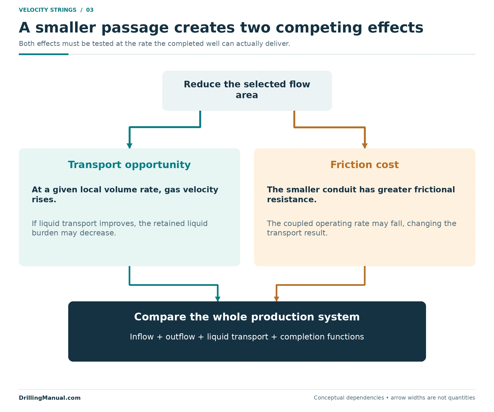
When gas can carry more liquid out of the well, less liquid may remain to contribute to the hydrostatic pressure burden. At the same time, forcing production through a smaller conduit increases its frictional resistance. The NOV CTES discussion explicitly connects smaller CT with greater friction and a potentially lower achievable operating rate. Both effects belong in the comparison. [1, pp. 10-33–10-34]
A useful design discussion therefore separates three questions. What gas rate can the reservoir supply at the resulting flowing pressure? What pressure does the completion require to pass that rate to surface? At that operating condition, can the gas transport the expected liquid through the relevant parts of the path? Answering only the last question at an assumed rate leaves the first two unresolved. [1, pp. 10-31–10-34]
The hydraulic benefit need not be the highest initial gas rate. A candidate might sacrifice some instantaneous capacity while providing a more useful liquid-transport condition. Another might restrict production so severely that the proposed benefit is lost. Which outcome applies depends on the well, and the manuals call for hydraulic and economic evaluation rather than a universal preferred diameter. [1, pp. 10-31, 10-34]
Compare Velocity String Performance at Achievable Rates
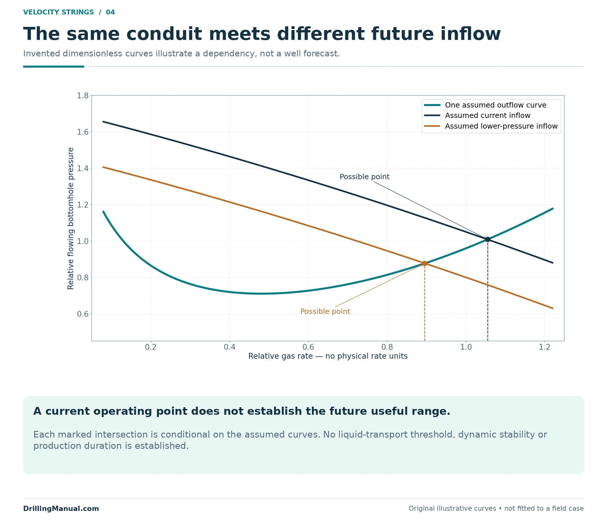
Nodal analysis brings reservoir inflow and completion outflow together. The inflow performance relationship describes the reservoir side. The outflow relationship includes the pressure needed to move the produced fluids through the selected path. Their intersection is a possible operating point within the assumptions of that analysis. It is not, by itself, evidence that a multiphase well will remain dynamically stable or unload indefinitely. [1, pp. 10-31, 10-33–10-34]
Compare proposed strings at their own calculated operating conditions. Do not take the rate from the existing large tubing, insert it into every smaller diameter and describe each resulting velocity as a production forecast. That exercise is an area sensitivity calculation, like the example above. A complete comparison must let pressure losses and achievable rate respond to the changed conduit. [1, pp. 10-31–10-34]
Also retain the surface boundary. A model built around one wellhead or downstream condition should not silently represent a different one. The source material identifies wellhead pressure, flowing bottomhole pressure, production history and completion configuration among the candidate information. The calculation is specific to those inputs. [1, p. 10-33] [2, p. 7]
Check the Velocity String Against Future Conditions
Reservoir depletion can move the available inflow away from the condition used to select the string. NOV CTES therefore recommends evaluating current inflow and projected performance at lower reservoir pressure. A velocity string that looks attractive at the present rate may have a much narrower useful range later. Future fluid production and the selected setting depth also belong in that assessment. [1, pp. 10-33–10-34] [2, p. 7]
Figure 4 uses dimensionless, invented curves to show this relationship. The same outflow curve intersects two assumed inflow curves at different rates. It contains no critical-rate boundary and makes no life prediction. A real forecast would have to revisit fluid properties and the outflow model as conditions change, rather than assume that every future curve keeps the illustrative shape.
Setting depth belongs in the same review. A proposed string defines a particular route through the existing completion; reducing area in one part does not establish transport adequacy everywhere else. Record where the selected conduit starts and ends and which passage carries production beyond those points. The source includes string setting depth and completion configuration in candidate evaluation, so a diameter without its intended geometry is an incomplete proposal. [2, pp. 7, 9]
Which Passage Actually Carries Production?
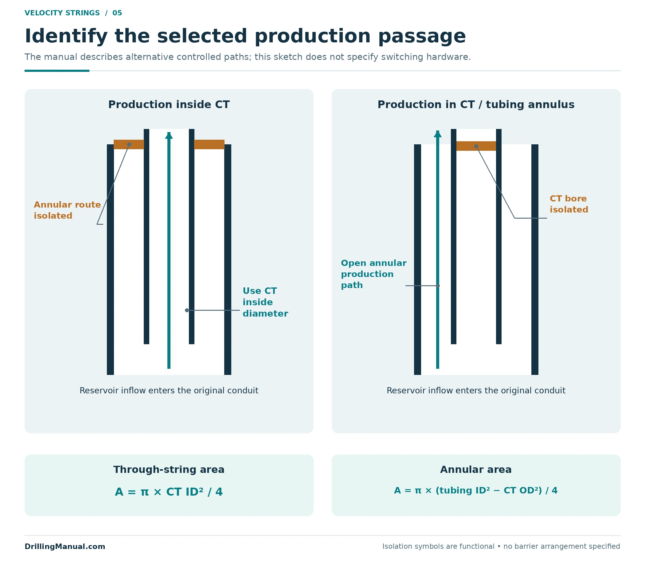
“CT installed” does not fully describe the flowing configuration. The Schlumberger manual describes two alternatives: use the CT bore for production and isolate the surrounding tubing annulus, or use that annular passage while isolating the CT bore. It also discusses designs intended to change the production path as conditions evolve. These are engineered alternatives, not an instruction to open both passages or improvise a switch. [2, p. 9]
| Selected production path | Dimensions that define its ideal area | Separate completion question |
|---|---|---|
| Inside the smaller string | Its internal diameter: A = πID²/4. | How is the surrounding annular route isolated and the string connected to the production outlet? |
| Between the smaller string and original tubing | Original tubing ID and smaller-string OD: A = π(ID² − OD²)/4. | How is the smaller-string bore isolated and the annular outlet controlled? |
| A planned change between those paths | The area and restrictions of each selected configuration. | What equipment and approved operating states provide the intended isolation and safety functions? |
The inside diameter belongs in a through-string calculation; the outside diameter belongs in the annular subtraction. Confusing them changes the calculated area before any multiphase model is applied. Figure 5 shows flow topology only. Its isolation symbols do not specify a barrier design, valve arrangement or field switching procedure. [2, p. 9]

A Velocity String Also Changes Completion Access
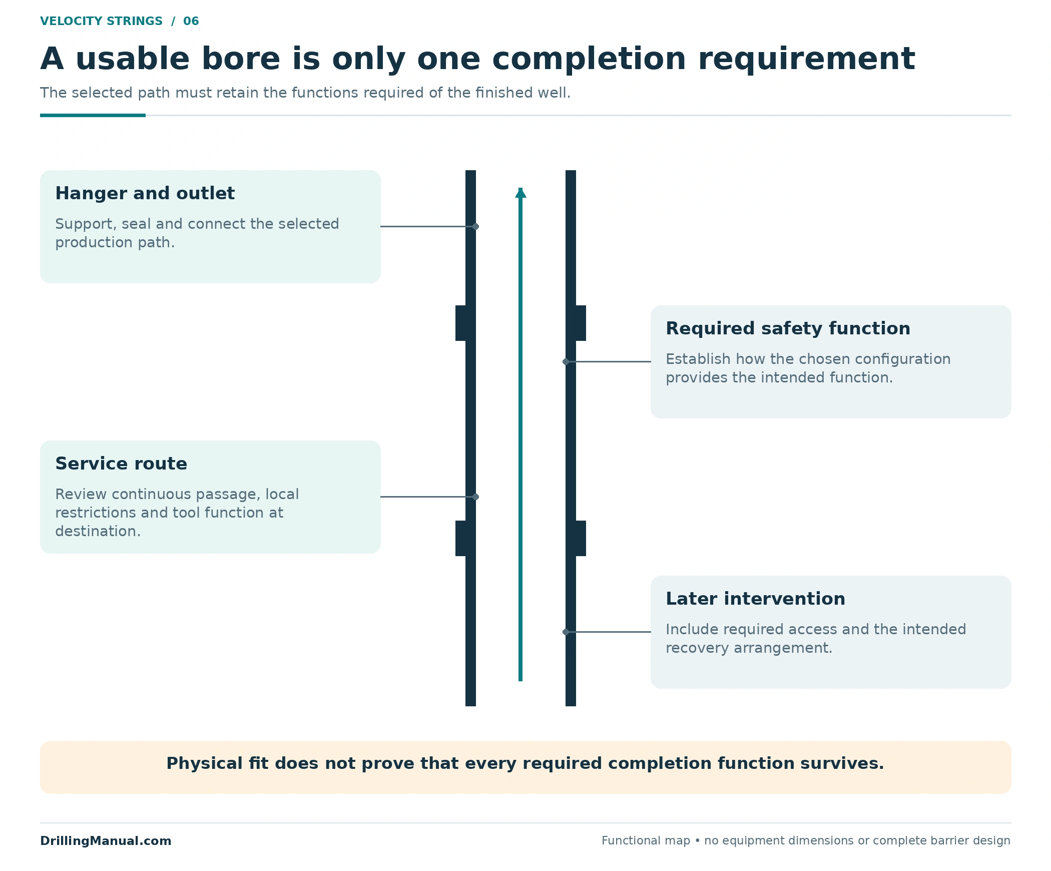
The proposed bore must support the functions required of the completed well. The Schlumberger manual treats hydraulics and mechanical loading as parts of a complete system and identifies bore size, wireline access, profiles and safety-valve compatibility as design considerations. A conduit that passes the hydraulic comparison can still be unsuitable for the required servicing arrangement. [2, p. 5]
Check the continuous access route, including local restrictions and equipment states, rather than only the nominal tube size. A future tool must fit and function at its destination; a string must also be supported and connected correctly. The installation can affect existing subsurface safety-valve and wellhead functions, so those functions must be deliberately provided by the chosen configuration. Their preservation cannot be inferred from the fact that CT physically fits inside the tubing. [2, pp. 5, 9]
This is why the equipment discussion should include later intervention and recovery needs. The surface equipment guide explains the main service-unit components, but their availability does not establish that a proposed retained completion has the required access or safety functionality. [2, pp. 5, 9]
Build a Candidate Comparison Before Choosing a Size
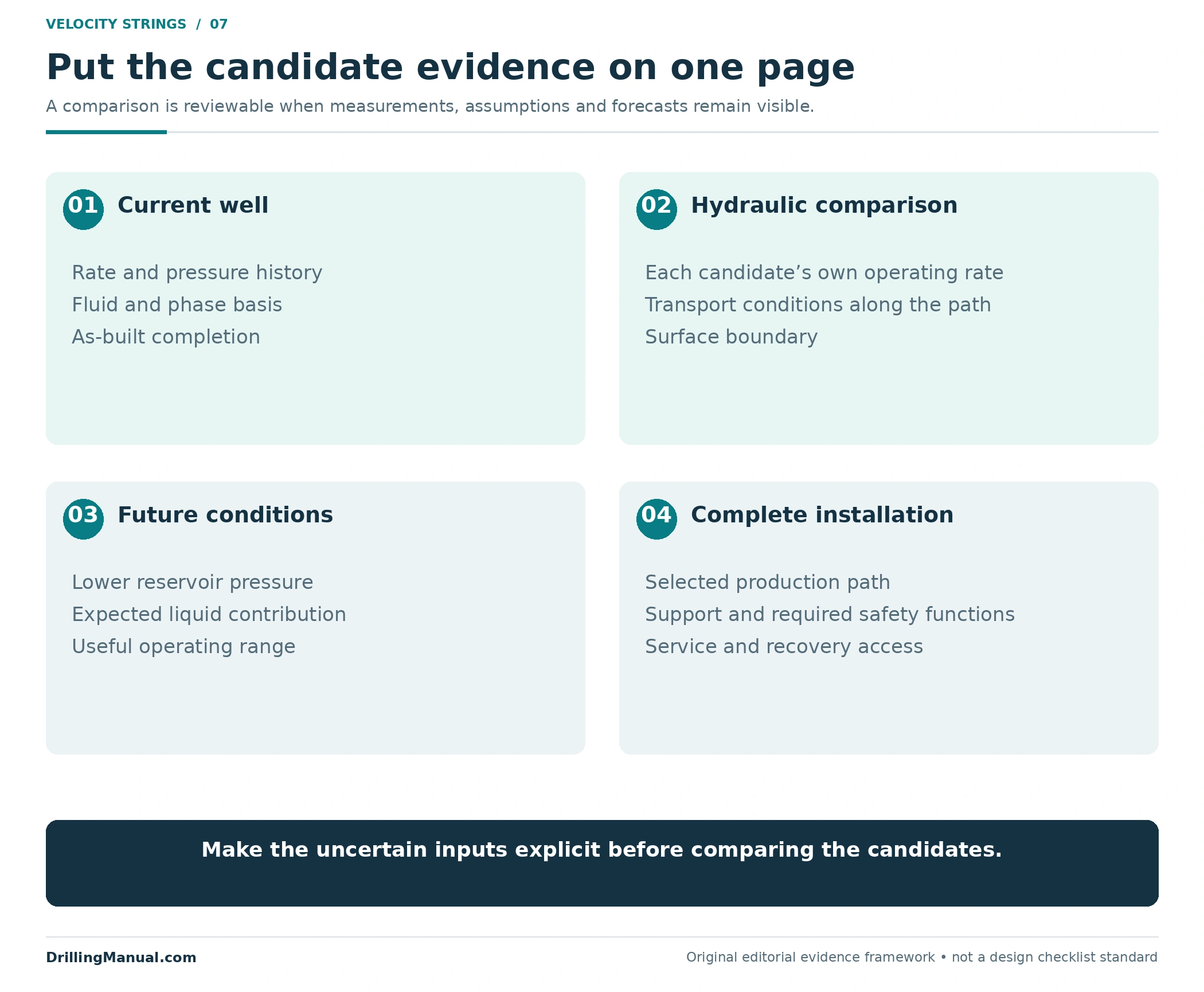
The following comparison is an editorial application of the manuals’ hydraulic and completion principles. It organizes the evidence a proposal should contain; it is not a replacement for a well-specific design or load assessment. A velocity string should be judged as a complete production option, including the assumptions that could change the result. [1, pp. 10-31–10-34] [2, pp. 5, 7, 9]
| Candidate question | Useful comparison | Reason to revise or reject the proposal |
|---|---|---|
| Can the well supply the modeled flow? | Current and future inflow against each candidate’s outflow. | The assumed transport rate is not achievable in the selected conduit. |
| Can that flow carry the expected liquid? | Relevant pressure, temperature, fluid and trajectory conditions along the path. | A single surface-rate or velocity number stands in for the entire well. |
| Does the completion still perform its required functions? | Selected production path, isolation, support, safety functions and service access. | The proposal checks diameter but leaves a required function unresolved. |
| Is the useful response worth the intervention? | Expected production range and duration, uncertainty, installation and later intervention costs. | The case depends only on the most optimistic initial response. |
Keep the original measurements with the assumptions. A rate inferred from an old test, a forecast reservoir pressure and a current geometry survey have different evidential status. Showing those differences makes the comparison easier to challenge and update. The inputs should support a decision, not conceal uncertainty behind a single selected diameter.
For instance, two candidate proposals may use different outlet pressures or different expected liquid rates. Their predicted gas rates are then not a clean comparison of tubing size. First identify those changed assumptions. Then ask whether the candidate ranking survives a consistent set of conditions and a reasonable range of the uncertain inputs. This is an original comparison method based on the manuals’ requirement to evaluate inflow, outflow and the complete installation together. [1, pp. 10-31–10-34] [2, pp. 5, 7]
A velocity string proposal should also say what would make its conclusion change. A different future pressure, greater liquid contribution or an unresolved access restriction can alter the preferred option. Recording those dependencies makes later review possible when the well no longer matches the selection case. It also keeps a model result in its proper role: evidence for a decision under stated assumptions, rather than a guarantee of the eventual response.
The economic comparison needs that useful operating range as well. Installation cost alone cannot describe the value of a conduit whose expected benefit depends on future pressure and liquid production. Compare the proposed production response with the cost of providing and later servicing the complete arrangement. The manuals identify economics as part of selection, without establishing a universal financial ranking of sizes. [1, pp. 10-31, 10-34]
Judge the Result in Its Intended Operating Mode
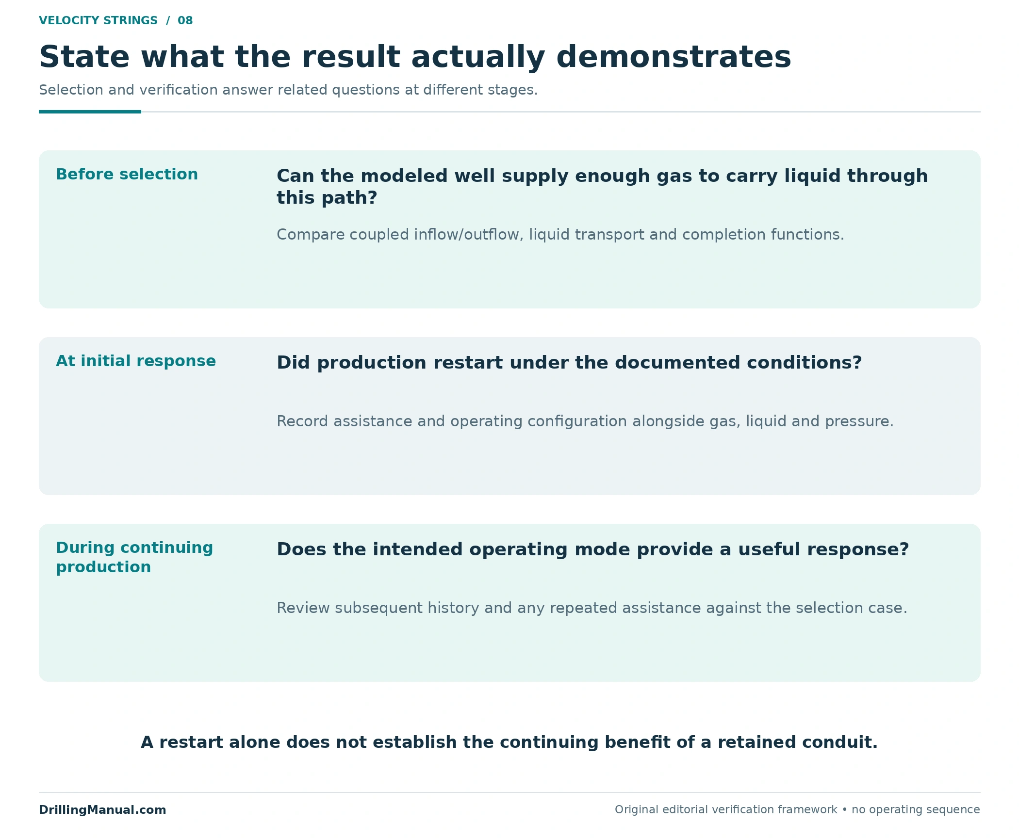
A retained conduit is meant to influence continuing production. An initial restart after assistance demonstrates a different thing from sustained liquid transport through the final completion. Define the intended operating mode and examine the subsequent gas, liquid and pressure response under the documented configuration. The manuals’ emphasis on expected production, current and future inflow, and complete-system performance supports this distinction. [1, pp. 10-33–10-34] [2, pp. 5, 7]
The velocity string review should therefore retain both the initial response and the following production history. If the well needs repeated assistance, document that mode when assessing the result. A brief high-rate interval cannot establish the continuing benefit that justified leaving the conduit in the well.
For a temporary kickoff, see nitrogen lifting with coiled tubing. Other unloading arrangements have their own selection questions; the separate guides to plunger lift and gas lift explain those mechanisms. A velocity string comparison should establish why changing the retained flow area suits this well’s continuing requirement.

Common Questions About Smaller Production Tubing
Does a velocity string always increase gas production?
No. Smaller area can improve local liquid transport, while increased friction can lower the achievable gas rate. Compare the combined inflow, outflow and transport result. A benefit cannot be established from diameter alone. [1, pp. 10-31–10-34]
Is the smallest bore the best choice?
No. It creates the largest area reduction for a given starting conduit, but it also changes friction, capacity and access. The preferred option depends on the well’s hydraulic, mechanical and economic conditions. [1, p. 10-34] [2, p. 5]
Can standard gas rate be divided directly by downhole area?
That would not give the local gas velocity. Gas volume and density depend on pressure and temperature. A local transport assessment needs a consistent local volume basis and the relevant fluid conditions, not an unconverted standard-volume rate. [1, pp. 10-32–10-33]
Must production flow inside the coiled tubing?
Not in every configuration. The source describes through-CT and CT/tubing-annulus alternatives, each with the other route isolated. The selected path determines the correct area and the required surface and downhole arrangement. [2, p. 9]
Will the original safety valve still work?
That must be established for the chosen installation. The manual explicitly treats the existing safety-valve function and wellhead equipment as configuration issues. Physical passage of the string is not proof that the completed well retains every required function. [2, pp. 5, 9]
Can one critical velocity approve the design?
No universal value is used here. The cited transport model depends on fluid properties and conditions that vary along the well, and the achievable rate must also satisfy the coupled inflow/outflow assessment. Model applicability and trajectory remain part of the engineering evaluation. [1, pp. 10-32–10-34] [2, pp. 7–8]
Book References
- NOV CTES, Coiled Tubing Manual. Inspected chapter revision: 27 June 2014; copyright 2007–2013 NOV CTES. Chapter 10, “CT Hydraulic Performance,” printed pp. 10-31–10-34 (physical PDF pp. 294–297); Chapter 13, “Permanent CT Installations,” printed pp. 13-3–13-4 (PDF pp. 506–507).
- Schlumberger Dowell, Coiled Tubing Engineering Manual, Section 910, “Coiled Completions,” Revision A, September 1993, pp. 5–9. Printed and physical PDF page numbers are the same in this 15-page section.
The source manuals are also listed in the coiled tubing handbook collection. The calculations, candidate comparison and illustrations in this article are original teaching material. Their hypothetical dimensions and curves are not field designs.