Inflatable service tools have been used in the oil and gas industry for more than 50 years to perform a variety of remedial workovers. Inflatable well packers, bridge plugs, and cement retainer is used in open holes, cased holes, slotted casing liners, and gravel-pack screens in oil and gas wells, but they should be used only when conventional tools are not suitable. Cement Retainers are mainly used for Remedial cementing operations. These drillable retainers are set securely in any type of casing.
Inflatable tools are especially useful in open holes of uncertain size. Just like conventional packers (check also Permanent Packers) and bridge plugs, inflatable service equipment can be set up in any array (i.e., retrievable packer, resettable packer, retrievable bridge plug, and cement retainer), allowing the same operations to be performed as with conventional equipment.
Inflatable equipment is in neither compression nor tension. The pressure inside the inflatable element holds the equipment in place.
Inflatable Cement Retainer
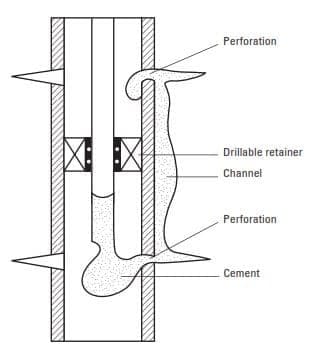
Inflatable cement retainer Combining a flapper-valve assembly (Fig. 2A) with a permanent inflatable bridge (Fig. 2B) creates a cement retainer. Cement retainers are usually used to squeeze off unwanted production or gas channels between the open hole and casing. The bottom bull plug is removed and replaced with a shear-out ball seat. The lift sub (Drilling Subs) on top is replaced with the valve assembly.
An inflatable cement retainer allows cement to be pumped into channels. Once the cement is in place, the hydrostatic pressure is relieved by pulling out of the retainer. Once out of the retainer, a valve closes and does not allow further squeezing.

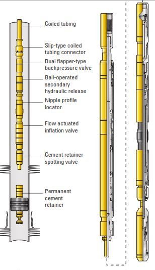
Through-Tubing Inflatable Permanent Cement Retainer
The through-tubing cement retainer (TTCR) (Figs. 3A and 3B) allows permanent isolation and cementation of a lower zone without pulling the production tubing and packer. The built-in retrievable spotting valve (Fig. 3B) provides a means of spotting cement to the top of the TTCR so that unwanted fluids are not pumped into the formation. Because the TTCR and spotting valve operations do not require rotation, the tool can be run on coiled tubing or threaded pipe. The TTCR houses opposing flapper valves, negating the chance of cement contamination after release of the running string from the retainer.
Cement Retainer Applications In Oil And Gas Wells
Circulating Squeeze
The circulating squeeze, illustrated in Fig. 4, is often performed with a cement retainer in preference to a packer. Circulation is achieved with water or acid as a preliminary fluid. The interval is circulated with a wash fluid to ensure good cleanup, and the cement slurry is then pumped and displaced.
No pressure buildup occurs during the job, except for an increase caused by the hydrostatic pressure of the cement column as it flows up the annulus. Once the placement is completed, the stinger or packer is released. The excess cement circulating out of the upper perforations can be reversed out if desired.
The volume of slurry required to complete a circulating squeeze is unknown; therefore, plenty of slurry is prepared. Consequently, there is a strong possibility that some of the cement slurry may enter the casing, drill pipe, or tubing or the annulus above the squeeze tool during the job.
Should this cement set, the drill pipe (or tubing) may become stuck in the hole. Therefore, to minimize this risk, a cement retainer should be run instead of a packer. It is easier to remove the stinger assembly than the packer, because the latter has minimal casing clearance. The retainer should be set as close as possible to the upper perforations. This minimizes exposure of the drill pipe to cement slurry that may enter the wellbore through the upper perforations.
Cement Squeeze
Cement Retainer is used also in cement squeeze jobs. Its usage is considered one of the types of Squeeze-tool placement techniques. This technique can be subdivided into two parts—the retrievable squeeze packer method and the drillable cement retainer method. The main objective of using squeeze tools is to isolate the casing and wellhead while applying high pressure downhole.
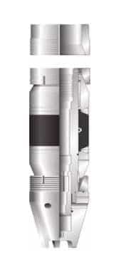
Cement retainers are drillable packers that have a valve that is operated by a stinger at the end of the workstring (Fig.1). Cement retainers are used to prevent backflow when no cement dehydration is expected or when a high negative differential pressure may disturb the cement cake. In certain situations, using a packer is risky because of potential communication with upper perforations. When cementing multiple zones, the cement retainer isolates the lower perforations and subsequent zone squeezing can be performed without waiting for the slurry to set.
A drillable retainer gives the operator more confidence in setting the packer closer to the perforations. Another advantage is that a smaller volume of fluid below the packer is displaced through the perforations ahead of the cement slurry.
Setting Mechanisms Of Cement Retainers
Drillable squeeze packers, commonly referred to as cement retainers (Fig. 11-133), maybe set on wireline or tubing. They are generally made of cast iron and are made compact to minimize drilling time. A sliding sleeve or poppet valve is provided to control slurry placement and preserve final squeeze conditions. Sliding sleeve valves are operated by raising and lowering the tubing. They prevent flow in either direction. Cement retainers are often used instead of retrievable packers to prevent backflow of cement when dehydration is not expected as well as to isolate the treated area from pressures because of the reversing of excess cement from the tubing. Cement retainers are also better suited to situations in which potential communication with upper perforations or casing problems may lead to cementing a retrievable packer in the hole.
Cast-iron cement retainers are set using any of three methods:
- Wireline
- Drill Pipe
- Coiled Tubing
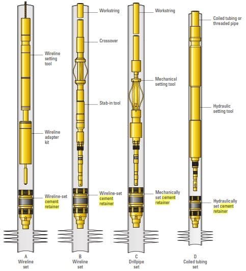
Wireline Set Mechanism
When accurate depth control is an issue, a wireline-set cement retainer (Figs. 5A and 5B) is deployed with an adapter to connect the cement retainer to the wireline setting tool. The cement retainer is lowered to the proper position and set by electrically firing a slow-burning charge in the setting tool. When the cement retainer is completely packed off, the setting tool shears free and is retrieved with the wireline. To cement through the retainer, a stinger is run on tubing, drillpipe, or coiled tubing and inserted into the cement retainer.
Setting On Drill Pipe
The second method of setting is on drillpipe or threaded tubing (Fig. 5C). Either tubing or drillpipe is used because of the need to rotate the tubing to set the cement retainer.
Setting with Coiled Tubing
The third is the coiled tubing setting method (Fig. 5D). The cement retainer is connected to a tubing setting tool, and a valve is opened to allow the tubing to fill as the cement retainer is lowered. The valve is pushed open by lowering the tubing and closed by raising the tubing. Hydraulic pistons push out the top slips, allowing the retainer to be set by pulling up on the coiled tubing. The stinger is connected and run in the hole with tubing to perform the squeeze. Rotating the tubing to the right releases the upper slips and initiates packoff in some models. The tubing is then pulled to complete the packoff. When the proper setting tension is achieved, the setting tool shears free. The setting tension may range from 18,000 lbf [80 kN] for 4 1 ⁄2-in. sizes to 48,000 lbf [214 kN] for 9 5 ⁄8-in. sizes.
Notes
when using a cement retainer for a squeeze operation, the fluid may flow upward into the annulus and pressurize the outside of the casing above the retainer. To prevent casing collapse in these situations, it is a common practice to pressurize the pipe-casing annulus
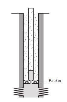
When a retrievable cement retainer is used in a circulation squeeze, its upper surface should be cleaned from any cement that might have fallen on top of it.
Cement retainer set with coin tubing string, how many time it can be string in to ensure it is seal properly?