In Drilling Torque and Drag Calculations, we will discuss how to manually calculate the total Torque & drag in the drill string. Then we will direct you to the torque calculations section also we will provide you with simple examples showing how to calculate. In addition to the above, you can also download a torque and drag excel spreadsheet to help you in your calculations.
Drilling Torque & Drag | Drag Calculations
Definition Of The Drilling Drag
Consider an object of weight W is resting on a horizontal plane. In order to slide the object a force Ft must be exerted to overcome the force of friction Ff between the object and the plane surface.

The magnitude of the frictional force is as following
Ff = μ W
where,
Ff = frictional force, lb
µ = Friction Coefficient, dimensionless is a constant that depends on the roughness of the object and plane surface, Determined experimentally.
W = normal force acting perpendicular to the surface, lb
Therefore, the force Ft (Drag Force) required to slide the object should be slightly greater than Ff (friction Force)
Drilling Drag Calculations
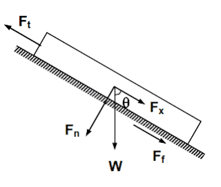
Now consider a section of Drill Pipes in a wellbore inclined at an angle I
1- A The buoyed weight ( Buoyancy ) of the Drill Pipes (W) is acting vertically downward and can be resolved into two forces
- Fn (normal force acting perpendicular to the hole)
- Fx (the weight component acting parallel to the hole axis).
Fn = W sin θ
Fx = W cos θ
2- The frictional or drag force Ff is the normal force times the Friction Coefficient.
Ff = Fn µ =W µ sin θ
3- The force Ft required to move the Drill Pipes is determined by making a force balance
Ft = Fx + Ff
Ft = W cos θ + W µ sin θ
The frictional force or drag always acts in the opposite direction of the pulling force Ft. If the Drill Pipes is lowered into the hole, the frictional force will act in a direction opposite to that.
Drill String Drag Calculations In Deviated Hole
In a curved section of the wellbore where inclination and azimuth change across the section, the calculation of the drag force is more difficult.
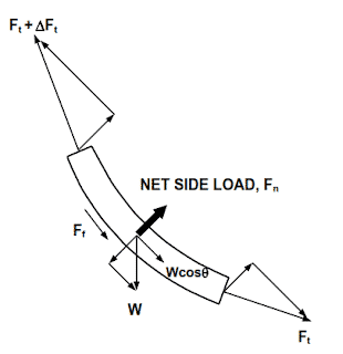
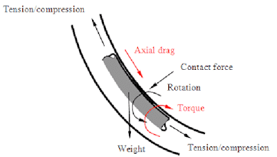
This drawing shows that the forces acting on a short slightly curved element of the Drill String.
1- The weight of the element
2- Normal forces from the tension forces Ft and Ft + ΔFt as a result of the change in the angle of inclination and the azimuth of the wellbore.
The magnitude of the resultant normal force can be estimated by an equation presented by Johancsik, Friesen, and Dawson,
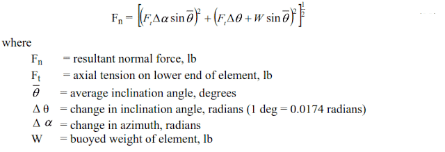
If the Drill String is moved uphole (or downhole) while being rotated as in back reaming, the drag force is calculated by using the following equation,
What Is The Relation Between Critical Hole Angle And Drill String drag force
When the weight component of the drill string in the direction of the hole axis is equal to the drag force-resisting downhole movement, the drill string is not able to slide downhole by its own weight and when drilling in the sliding mode the drill string will require pushing with pipe higher in the hole. The angle at which downhole movement becomes impossible is called the critical hole angle,
θcr = arctan ( 1 / µ )
Drilling Torque & Drag | Torque Calculations
What Is The Drill string Torque in drilling
We can define the drill string torque as it is the rotational force that is required to overcome all the frictional forces between the drill string and the formation while drilling string rotation. The drilling Torque Calculations part will give you a hand in understanding how to calculate the torque required to turn the drill string.
Drilling Torque & Drag | Torque Calculations Equation
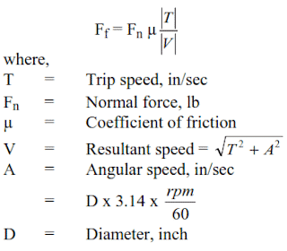
The torque required to turn the drill string is calculated by the following equation,
Torque = Fn r µ (A/V)
Where:
T = Torque, ft-lb
Fn = normal force as defined
R = Radius of drill string component ft (for drill collars use outer radius of collar, for DP, HWDP and casing use outer radius of tool joint)
µ = Coefficient of friction
A = Angular speed
V = Resultant speed
From drill string torque definition, If the drill string is not tripped while rotating, then T = 0 and A is equal to V and The Equation reduces to
Torque = Fn R µ
If the torque acting on the lower end of the drill string element is M, then the torque acting at the top of the element is M + ΔM . The torque increment ΔM is
ΔM = Fn R µ
Where :
Fn: is the normal force exerted on the element.
The torque required to turn the entire drill string is the sum of all torque increments for all the elements.
Examples on Drilling Torque And Drag Calculations
This example will learn you how to manually do drilling torque and drag calculations. Of course we are not using these calculations now but it is mentioned for a better understanding of drilling torque and drag calculations. Then you can download torque and drag excel spreadsheet.
Download Drilling Torque And Drag Excel Spreadsheet
This amazing worksheet which was done by DrillByte can be used to do Drilling Torque And Drag Calculations.

Factors Affecting Torque And Drag In Drilling
When planning a 3D well trajectory, one of the most important considerations is torque and drag. If the torque and drag are not carefully considered, the drill string might fail. The torque and drag model used makes special assumptions that simplify the analysis and are used to model real drill strings. The most important factor influencing the torque and drag forces is the hole curvature. The well path should be redesigned with a smaller build-up rate if the drill string seems to fail when simulating these forces during the design stage.
There are many causes for excessive torque and drag such as sliding friction, tight hole, collapsing or swelling clay/shale, key seats, differential sticking, and cuttings build-up. The minimum curvature method assumes the bending part in the equilibrium equation used to calculate torque and drag is discontinuous at survey stations. Some authors mean this is one of the main weaknesses of using the minimum curvature method. Due to the missing bending stresses, the method might not represent the real drill string configuration.
Kick-Off Point affect torque and drag in Drilling
The kick-off point is often the major factor influencing Drill String Torque and Drag in a well. This is due to the fact that shallow doglegs combined with pipe tension will cause a high normal force, thus a high drag and torque at that point.
In deep directional wells, the kick-off point should be considered from a Torque and Drag standpoint, in addition to the other factors influencing the kick-off point.
Wellbore Tortuosity / Dogleg Severity
Tortuosity can be defined as a measure of deviation from a straight line. It is the ratio of the actual distance traveled between two points, including any curves encountered, divided by the straight line distance. Tortuosity is used by drillers to describe wellbore trajectory, by log analysts to describe electrical current flow through rock and by geologists to describe pore systems in rock and the meander of rivers. As directional wells become deeper and sophisticated, unwanted deviations from the pre-planned well trajectory occur frequently. Any unwanted deviation from the wellbore trajectory is regarded as wellbore tortuosity. The change in inclination and azimuth influence the normal force acting on the Drill Pipe. The larger the change in either, meaning increasing dogleg severity, the larger the normal force and the larger the increase in drag due to that point. Smaller doglegs lead to less Torque and Drag.
The effect of Mud Lubricity on torque and drag analysis
Mud lubricity is a term generated from a lab test (on a specific piece of equipment) that is intended to minimize the Drill Pipe /casing interaction. The lubricity is scaled opposite the friction factor, increasing lubricity reduces the friction factor.
Hole Cleaning
Hole cleaning is an important factor. A proper hole cleaning is a must during drilling operations to reduce the unwanted cuttings in the Mud Circulating System as these cuttings have the potential to resist in drill string rotation and movement. In a directional wellbore, cuttings tend to accumulate up in the high angle build section; this is why removing the cuttings from the hole is difficult. Improper hole cleaning also brings the risk of damaging downhole tools such as MWD tools and mud motors. However, if an MWD tool is employed on the drill string, cuttings intensity in the mud can be monitored by following the parameter called Equivalent Circulating Density (ECD), which is the apparent drilling fluid density. An increasing trend of ECD will imply the accumulation of cuttings in the wellbore.
Cuttings beds will locally change the effective Friction Coefficient and can be modeled in that manner if the location, length, and friction factor of the cuttings bed is known. Unfortunately, these parameters continually change in the presence of a cuttings bed.
The typical technique is to deduce the presence of a cuttings bed when unexplained trends in Torque and Drag develop in well. This would be seen very practically on a trip out of the hole when pick-up weight begins increasing during the trip, rather than decreasing, then suddenly returns to the baseline trend.
Drilling Tools
It is not hard to imagine that the influence of a Drilling Stabilizer on drag would be much greater than that of a similar length of Drill Pipe or Drill Collar and that the interaction of the stabilizer with the well-bore may include additional components than does the simple model we have been working with Drilling tools can greatly impact Torque and Drag are stabilizers, Drill Pipe protectors, Drilling Bits Type (roller cone vs. drag type), drill collars (flex vs. slick) and hard banding on Drill Pipe.
Hole Instability
Hole instability is a displeasing case that occurs when the original hole size, shape, and structural conditions of a borehole are not well maintained. It appears with the failure of balance between the rock strength and in-situ rock stress at some depth during drilling. It may also arise with the effects of drilling fluid such as erosion in the borehole and chemical interactions of drilling fluid with drilled formation. Hole closure, which is the narrowing process of the borehole, results in an increase of torque and drag.
Key Seating
Key Seating is the condition when a tubular of a small diameter is worn into the side of a larger diameter borehole. It is generally a result of severe hole direction changes such as a high dogleg or a hard formation ledge left in soft formations which erode and enlarge in time. In both cases, the diameter of the drilled hole is expected to be close to the diameter of the drill pipe. The larger diameter tools such as stabilizers, drill collars, and tool joints are not able to pass through the key seat and become Drilling Stuck Pipe which will result in problems associated with high torque and drag. The preventive method is to enlarge the point of the key seat so that the tools with larger diameters can pass through it
Related Papers To Torque & Drag In Drilling
Don’t forget to use Sci-Hub Services to open any paper if you are not able to pay for its access.