Drilling reamer types serve different bottomhole-assembly (BHA) purposes: maintaining hole gauge, conditioning irregular sections or enlarging a pilot hole. The main equipment families include roller reamers, fixed-diameter hole openers and expandable underreamers. A near-bit reamer describes where the tool is positioned; RFID describes one method of commanding a downhole reamer. These terms are not five mutually exclusive reamer families.
Choosing the right tool depends on the objective: smooth an undergauge hole or ledged borehole, support directional BHA geometry, or deliberately cut a larger hole for a casing/liner program. The tool must also pass every restriction above its operating depth and fit the well’s hydraulic, mechanical and pressure-control limits. See our BHA components and design guide for the surrounding assembly.
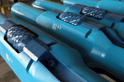
Drilling Reamers: Applications in Oil and Gas
Reamers may improve wellbore gauge and help manage local restrictions, but they do not replace an assessment of the cause of a tight hole. Swelling shale, mobile salt, cuttings beds, doglegs, keyseats & mechanical sticking, differential sticking and worn bit gauge create different problems. The correct response can involve fluid conditioning, improved hole cleaning, changes in BHA geometry, a dedicated reaming run or a redesign of the casing and hole-size program.
- Gauge maintenance: roller reamers can contact and smooth minor irregularities while helping support the selected BHA gauge; they do not normally create a substantially larger planned hole.
- Hole enlargement: a fixed hole opener or expandable underreamer cuts a specified final hole diameter beyond a smaller pilot hole.
- Below-casing enlargement: an expandable tool can pass through a restriction in its retracted condition, then open below it and retract for retrieval, provided its collapsed OD meets the actual restriction/drift.
- Directional drilling: a near-bit reamer or roller-reamer stabilizer may influence the contact points that affect steering; confirm compatibility with the RSS or mud-motor BHA.
- Casing access: reaming may provide the clearance required for casing running or liner operations, but final hole gauge and the actual wellbore condition still require verification.
Important distinction: a separate reaming trip and reaming-while-drilling are operating methods; roller cones, PDC blocks and blades are cutting structures; mechanical, hydraulic, ball/dart and RFID systems describe different activation/control approaches. These categories can overlap in a single tool.
Drilling Reamer Types
The comparison below classifies drilling reamer types by their primary function, rather than a trade name. It also shows which tools can pass through casing restrictions before cutting a larger hole.
| Tool or configuration | Primary job | Restriction / deployment consideration | Typical limitation |
|---|---|---|---|
| Roller reamer | Maintain/restore gauge, smooth minor irregularities, provide rolling contact and selected stabilization | Fixed-gauge components must pass the minimum restriction | Roller/cutter wear, bearing damage, limited planned enlargement |
| Fixed-diameter hole opener | Enlarge a pilot hole to a predetermined diameter | Cannot pass a restriction smaller than the fixed cutter gauge | Usually unsuitable for enlargement beyond a smaller casing drift |
| Expandable underreamer | Enlarge a hole below casing or another restriction | Retracted tool must pass restrictions; cutters extend only where permitted | Deployment/retraction assurance, rathole, wear and added cuttings load |
| Near-bit reamer | Condition/enlarge close to the bit and manage near-bit contact points | Placement in the BHA, not one universal cutter or actuation type | Directional response, BHA spacing, tool compatibility |
| RFID-controlled reamer | Command actuation of a compatible expandable reamer | Requires a model-specific tag/reader/actuation process | Communication, tag delivery and confirmation depend on design |
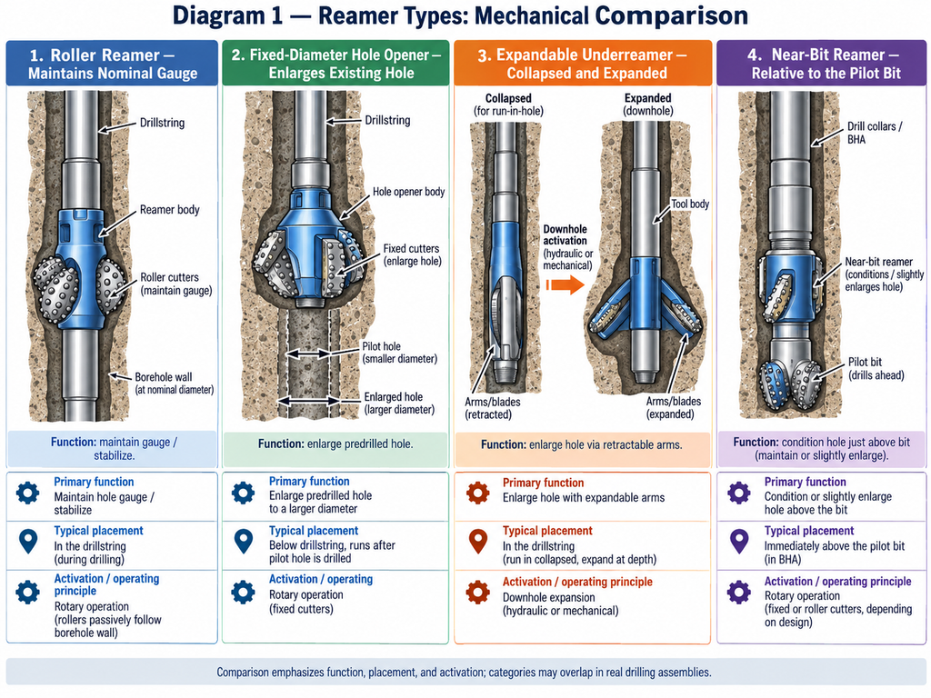
For fixed-gauge enlargement, consult the separate hole-opener guide. It is not technically correct to classify all hole openers as hydraulically expandable underreamers. SLB’s underreaming definition distinguishes the enlargement operation from the specific tool design.
Under-Reamers
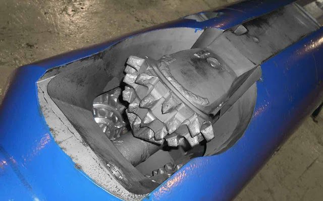
An underreamer enlarges a wellbore from an existing diameter to a larger planned gauge. Among drilling reamer types used for deliberate enlargement, expandable underreamers are especially valuable below a casing shoe: the tool runs through the preceding casing/liner in its retracted state, opens below the restriction, and retracts before recovery. Depending on the manufacturer, activation may use hydraulics, a ball/dart sequence, or another approved control system.
The planned expansion must be checked against casing drift and tool collapsed OD, cutter extension and retraction envelope, downhole temperature/pressure rating, drillstring hydraulic capacity, and the final clearance needed by the next tubular. A nominal casing OD is not the internal clearance available to the tool.
Drilling Under-Reamers Components
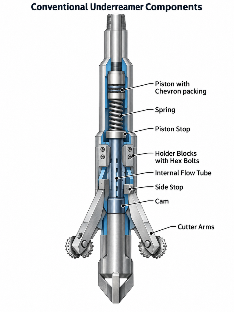
- Body and connections: transmit drillstring loads and contain internal flow passages.
- Cutting blocks, blades or arms: carry roller-cone or fixed cutters; the arrangement defines the enlargement gauge.
- Actuation mechanism: hydraulic piston, sleeve, valve, latch or other model-specific components that deploy the cutting structure.
- Locking and retraction features: support controlled deployment and retrieval through restrictions.
- Seals, bearings and instrumentation: included as required by the cutter system and selected tool model.
Pre-run checks must confirm the manufacturer’s exact assembly configuration and failure response. An increase or decrease in surface pressure alone is not universal proof that every cutter has fully reached gauge; some systems offer additional downhole cutter-position or wear measurements.
Under-Reamers Types and Applications
Applications include increasing annular clearance for casing or liner deployment; creating a bore diameter for a planned cementing program; and enlarging a pilot hole when the casing through which the BHA must pass prevents running a full-gauge bit. The need for underreaming must be demonstrated by the actual casing/liner, casing selection and wellbore design, not assumed for every directional or casing-while-drilling operation.
The extra rock removed must be transported to surface. Before selecting an enlarged hole diameter, calculate expected generated cuttings volume, review hydraulic capacity and equivalent circulating density (ECD), and assess hole stability and the consequences of additional open-hole exposure.
Underreamer Cutter-Structure Designs
- Roller-cone cutter underreamers: use rolling cutting elements; performance and reliability depend on bearings, seals and formation abrasiveness.
- Hinged-arm PDC designs: deploy cutter-carrying arms from the tool body; hinge/pin wear and actuation must be considered.
- Block-type PDC designs: extend cutting blocks to the programmed diameter; cutter layout and hydraulics must match the pilot bit and formation.
These describe illustrative mechanical/cutting-structure designs, not a complete or current market ranking. Manufacturers offer additional variants and different actuation cycles. The correct model must be chosen against the actual application envelope.
Drilling Roller Reamers
Among drilling reamer types used for gauge conditioning, roller reamers use rolling cutters that contact the borehole wall. They may be placed near the bit or at other selected BHA positions to reduce sliding contact, maintain gauge, smooth minor restrictions and influence stabilization. They can be useful where abrasive formations produce severe stabilizer gauge wear or high rotary torque. However, they are not automatically the best reamer for every hard formation, and their use does not guarantee elimination of stick-slip or bit whirl.
The uploaded Well Engineering & Construction textbook, Drillstring Design, Section 5.1, describes three-point and six-point roller-reamer configurations and emphasizes cutter-bearing condition, gauge wear and formation-appropriate cutting surfaces. Those details belong in a selection decision alongside the stabilizer design and the planned BHA build/hold/drop tendency.
Roller Reamer Type Components
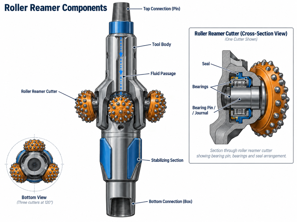
A three-point roller reamer has three rolling cutter positions around a section; some designs use two longitudinal sets, commonly called six-point reamers. Exact arrangement, bearing protection, body length and connection details are manufacturer-specific.
- Roller cutters: gauge-contact surfaces selected for formation hardness, abrasiveness and required service life.
- Roller pins/shafts: support cutter rotation and transfer contact loads into the body.
- Bearings and seals: govern rolling resistance, wear resistance and debris ingress; sealed-bearing choices should be reviewed when available.
- Body and bearing blocks: establish cutter position and provide the load path.
- Retaining hardware: pins, locking features and fasteners appropriate to the specific product drawing.
When inspecting a roller reamer, focus on cutter freedom, bearing condition, secure retention and remaining gauge. A nominally full-gauge body with worn rollers may not provide the intended hole contact or directional response. Do not substitute a model-specific assembly method from another vendor’s tool.
Drilling RFID Reamer Types
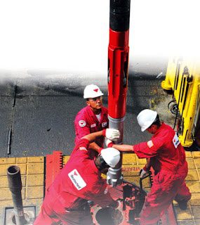
RFID describes the control method, not a separate cutter family. On compatible tools, a programmed radio-frequency identification tag travels with the drilling fluid to a downhole reader. The tool interprets the instruction and executes an approved activation, deactivation or status sequence, depending on the model. For example, the original article illustrates a Weatherford RFID-controlled reamer; its functionality should be checked against its specific operating manual.
Potential advantages include selective actuation without an additional trip, avoidance of unintended deployment in some operations, and the ability to manage separate tools in designs that support independent addressing. However, no control method guarantees that cutters will always actuate/retract or that a tool cannot become stuck. The required surface indications and any downhole confirmation must be established during pre-job planning.
Drilling Near-Bit Reamers Type
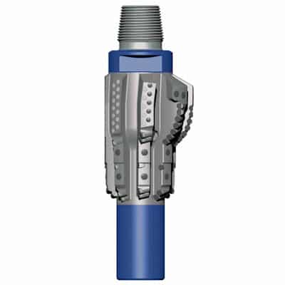
A near-bit reamer is positioned near the bit to condition the hole or perform enlargement close to the pilot cutting structure. Depending on its construction, it may have fixed rolling elements or expandable cutters. BHA placement affects directional steering, bit-to-reamer loading, borehole contact and the length of unreamed hole at section TD.
Near-Bit Reamer Applications
- Condition localized tight or ledged intervals where a near-bit location is preferable to an upper-string tool.
- Enlarge a pilot hole using a near-bit system rated for the planned BHA and the steering equipment.
- Reduce the unreamed bottom interval relative to a reamer placed much farther above the bit; the actual benefit depends on spacing and actuation geometry.
Near-bit reaming does not always require a backreaming trip. Justify backreaming by wellbore conditions and the approved procedure; it can add cuttings and disturb unstable formations. See reaming, backreaming and stuck-pipe risks.
Expandable Reamers Type
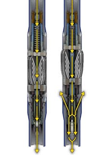
Expandable reamers are a mechanism within the broader underreamer family. The cutter blocks or arms extend to cut a diameter larger than the tool’s running gauge. Some designs support repeated activation cycles, while others require particular ball/dart or sleeve sequences. Always identify whether the tool can circulate with cutters retracted, how retraction is confirmed, and what can be done if the system does not behave as commanded.
Rathole: when the underreamer is located above the pilot bit, an interval near bottom may remain at the smaller pilot-hole diameter because the enlarging cutters cannot reach the same depth as the bit. Its length is primarily related to bit-to-reamer spacing and the exact run/activation arrangement, not a universal 100–300 ft. A near-bit or specialized rathole-reduction system can change this geometry. The completion and casing-running design must account for any smaller-diameter interval.
Do not assume that a selected underreamer guarantees full enlargement simply because the intended cutter size is known. Wear, inadequate expansion, formation response, or survey/caliper uncertainty may leave undergauge intervals. A 2019 North Sea HPHT case study describes how cutter-position/wear monitoring and a post-run caliper helped verify a 12¼-in. pilot section enlarged to 14 in.; the result should be interpreted as case-specific evidence, not a universal assurance method.
Matching Bit and Reamer
For drilling reamer types designed to enlarge a hole while drilling, the pilot bit and underreamer remove rock in different parts of the same section. They must be matched for formation response, cutter aggressiveness, hydraulic demand, rotary speed, expected penetration rate, and the available weight/torque distribution. If one element requires substantially different cutting conditions, the result can be poor ROP, excessive dynamic loading, accelerated wear or loss of directional control.
Review the pilot bit’s cutter design together with reamer cutter exposure, nozzle arrangement, BHA stiffness, steering response, vibration risk, and connection ratings. Matching improves the probability of balanced loading; it cannot eliminate every vibration or hole-stability hazard.
Worked Example: How Much Additional Rock Does Underreaming Remove?
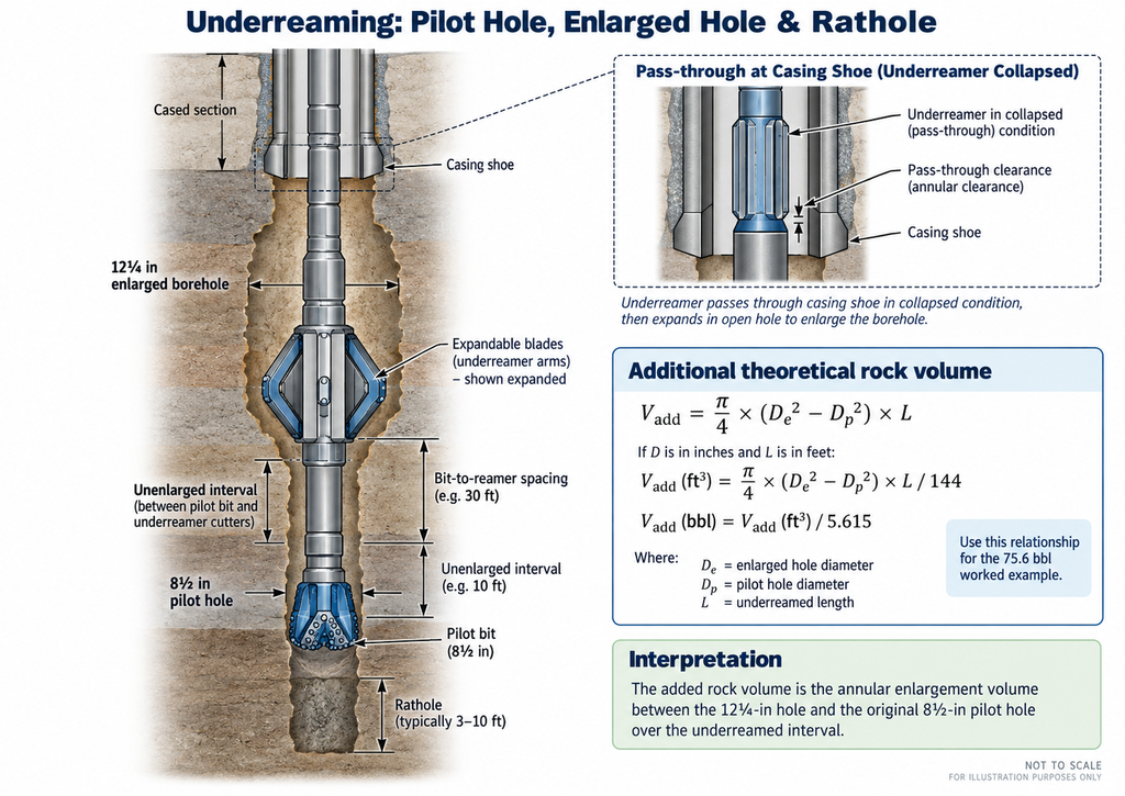
Consider a hypothetical pilot hole of 8½ in. enlarged to 12¼ in. for a 1,000-ft interval. The hole’s cross-sectional area is proportional to the diameter squared. Therefore, the theoretical additional in-situ rock volume removed per foot, expressed in barrels, is:
Additional hole volume (bbl/ft) = (Enlarged hole ID² − Pilot hole ID²) ÷ 1,029.4, with diameters in inches.
=(12.25² − 8.50²) ÷ 1,029.4 ≈ 0.0756 bbl/ft. Across 1,000 ft, the added theoretical excavated formation volume is 75.6 bbl. The larger hole’s cross-sectional area is approximately 108% greater than the pilot hole’s area.
This is a geometrical calculation—not a forecast of measured shaker volume or a recommended pump rate. The actual returned cuttings depend on borehole condition, formation bulking, washout, downhole cleaning and solids transport. The higher rock-removal load can increase the need for hole-cleaning capacity, especially in inclined sections. For the fundamentals, review hole cleaning in deviated and horizontal wells.
Selecting Drilling Reamer Types: Pre-Run Checklist
| Design question | What to verify | Why it matters |
|---|---|---|
| What is the objective? | Gauge restoration, stabilization, planned enlargement or casing clearance | Determines roller reamer versus fixed hole opener versus expandable underreamer |
| What can pass through the restriction? | Actual casing/liner drift; collapsed OD and connections; tool extension/retraction | Prevents selecting a tool that cannot be run or recovered |
| Will the hole be large enough? | Pilot and enlarged gauge, cutter wear allowance, rathole, completion clearance | Protects casing/liner and cementing objectives |
| Can the hole be cleaned? | Additional cuttings load, annular velocity, pump pressure, mud properties, ECD | Limits cuttings accumulation, pack-off and loss exposure |
| Is the BHA compatible? | Bit/reamer load sharing, steering, vibration, telemetry, tensile/torsional ratings | Prevents a tool combination that cannot be drilled reliably |
| How will status be confirmed? | Model-specific activation indications and any downhole measurement/verification | Avoids assuming full-gauge hole from indirect surface indications |
| What is the contingency? | Stuck/non-retracting tool, abnormal torque/pressure, undergauge interval, gauge verification | Protects barrier, retrieval and subsequent casing decisions |
Reaming and Backreaming: Operating Risks to Monitor
The uploaded Practical Drilling Skills material (Drill Strings, Section 11, “Stabilizers and Reamers”) describes roller reamers as gauge-conditioning and BHA-contact tools. The Best Practices: Prevention of Stuck Pipe slides and the historical ADCO Drilling Manual, Volume 1, Chapter 4, warn that aggressive reaming or backreaming can introduce solids faster than they can be circulated out, increasing pack-off risk.
- Before the run: identify known doglegs and tight spots, set approved torque/overpull/hydraulic limits, review available circulation capacity and contingency plans.
- During the operation: trend standpipe pressure, torque, drag, flow and shaker solids returns; investigate abnormal changes rather than assuming a tight spot is harmless.
- Before continuing: if indications suggest cuttings accumulation, loss, tool malfunction or incipient pack-off, follow the approved well-control and reaming response plan. Do not attempt to force the string through a restriction or improvise a hydraulic response.
- After the run: establish what evidence demonstrates acceptable hole gauge, cutter condition and casing-running readiness; a successful trip alone may not prove the whole enlarged interval is in gauge.
These considerations apply across drilling reamer types, but equipment-specific limits and verification methods remain essential. They are engineering planning and surveillance considerations, not substitute operating instructions. Detailed pump, rotary speed and overpull decisions are specific to the BHA, well condition and operator’s approved procedures.
Frequently Asked Questions About Drilling Reamer Types
What is the difference between a roller reamer and an underreamer?
A roller reamer normally contacts and conditions the existing hole to maintain gauge and stabilize the BHA. An expandable underreamer deliberately cuts the hole to a larger diameter, often below casing or another restriction. Some underreamers use roller cutters, so the names alone do not define the complete tool mechanism.
How is a hole opener different from an underreamer?
A fixed-diameter hole opener enlarges a pilot hole but must pass every restriction at its cutting gauge. An expandable underreamer runs through a smaller restriction while retracted and enlarges the hole after its cutters extend below that restriction.
Does using a reamer eliminate the need for backreaming?
No. Reaming may reduce the need for remedial work, but the decision depends on hole condition, available clearance and the planned trip or casing operation. Backreaming itself can increase solids loading and sticking risk.
How can engineers confirm that an underreamer cut the planned diameter?
Evidence may include the actuation signature, downhole tool-position or wear records when provided, post-run gauge measurements, and caliper data where justified. The required verification method depends on the application and approved well program; no single signal proves every tool is at full gauge.
References and Case Studies
- H. Rabia, Well Engineering & Construction, Drillstring Design, Section 5.1 “Roller Reamers,” p. 423 — three- and six-point systems, formation-dependent selection and gauge/bearing considerations (user’s engineering library).
- Practical Drilling Skills, Chapter 11 “Drill Strings,” p. 11-5, “Stabilizers and Reamers” — BHA gauge conditioning, directional contact effects and roller-reamer applications (user’s engineering library).
- Best Practices: Prevention of Stuck Pipe, “Reaming and Backreaming” slides — cuttings loading and pack-off mechanisms (user’s engineering library).
- ADCO Drilling Manual (historical, 2005), Volume 1, Chapter 4, “Reaming and Backreaming” — examples of risk-based surveillance; not a current operating standard.
- SLB Energy Glossary — underream (definition and scope).
- SLB — Borehole Enlargement (examples of specialized tool families and rathole-reduction technology).
- Drilling Contractor — North Sea HPHT underreamer monitoring case study (2019).
Scope note: Dimensions, cuttings-volume calculations and example tool capabilities must be checked against current vendor drawings and the approved well program. The historical manuals cited above are technical background, not a claim about current compliance or universal operating thresholds.