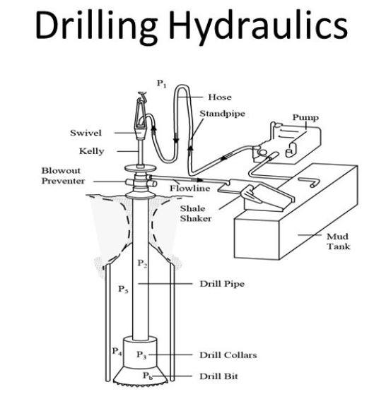
Why It Is Important To Understand Drilling Hydraulics? The drilling hydraulics system serves many purposes in the well. Since it is centered around the drilling mud circulating system, the purposes of mud and hydraulics are often common to each other.
The hydraulics system has many effects on the well. Therefore, the reasons for giving attention to drilling hydraulics are abundant. The more common reasons are as follows:
- Control subsurface pressures
- Provide a buoyant effect to the drill string and casing
- Minimize hole erosion due to the mud’s washing action during movement
- Remove cuttings from the well, clean the drilling bit, and remove cuttings from below the bit.
- Increase penetration rate
- Size surface equipment such as pumps
- Control surge pressures created by tripping the pipe into the well
- Minimize wellbore pressure reductions from swabbing when pulling pipe from the well
- Evaluate pressure increases in the wellbore when circulating the mud.
- Maintain control of the well during well kicks
Quite often, these effects are interrelated, increasing the optimization difficulty.
Hydrostatic Pressure
The hydrostatic pressure of the drilling fluid is essential in maintaining control of a well and preventing blowouts. In a practical sense, it is defined as the static pressure of a fluid column.
The hydrostatic pressure of a mud column is a function of the mud weight and the true vertical depth of the well. Attention must be given to the well depth so that the measured depth, or total depth, is not used inadvertently.
The equation constants will vary since mud weights and well depths are often measured with different units. Common forms of the hydrostatic pressure equation are as follows:
PH = 0.052 x (mud weight, Ib/gal) x (depth, ft)
Where:
PH = hydrostatic pressure, psi
0.052 = constant, psi/lb/gal
PH = 0.00695 x (mud weight, Ib/cu ft) x (depth, ft)
PH = 9.81 x (mud weight, g/cm3) x (depth, m)
Equivalent Mud Weight In Drilling Hydraulics
Drilling operations often involve several fluid densities, pressure from fluid circulation, and perhaps applied surface pressure during kick control operations.
The widely used approach is converting all pressures to an “equivalent mud weight” that would provide the same pressures in a static system with no surface pressure.
ECD or equivalent circulating density is another term commonly used to describe the equivalent mud weight concept. The ECD in drilling usually considers the hydrostatic pressures and the friction pressure resulting from fluid movement.
EMW= total pressures X 19.23 ÷ true vertical depth
Where:
EMW = equivalent mud weight, Ib/gal.
19.23 = reciprocal of the 0.052 constant Ib/gal/psi.
Buoyancy
The drilling fluid types provide a beneficial effect relative to drill string weight or hook load. The mud system supports or buys some of the pipe weight when the drill pipe is lowered into the well. This effect is termed buoyancy or buoyant forces. The buoyed weight of the drill string will be less than the in-air weight of the pipe.
In drilling hydraulics, Buoyant forces are a function of the volume and weight of the displaced fluid. Heavier muds have greater buoyant forces than low-density muds. The buoyed pipe weight can be calculated below Eq.
BW = (BF) x (in-air weight)
Where:
BW = Buoyed weight
BF = Buoyancy factor
BF = 1 – (mud weight / 65.5)
The constant of 65.5 is the density of a gallon of steel
CHAPTER 1: COMPLETE GUIDE FOR DRILLING MUDS FLOW REGIMES & RHEOLOGY MODELS
Flow Regimes are the behavior of the fluid while flowing in a well. The most common regimes are laminar, turbulent, and transitional. Unfortunately, it is impossible to clearly define each type in the well. For example, mudflow may be predominantly laminar, although the flow near the pipe waIls during pipe rotation may be turbulent.
Objective:
- Identify different types of drilling fluids flow regimes
- Understand flow regimes turbulence criteria and their relation with Reynolds Number
- How to identify flow regimes using the z factor method
- Learn why we need mathematical models
- Understand the differences between the Newtonian model, Bingham model & Power law model assumptions and equations
- How to calculate plastic viscosity and Yield Point for drilling mud
CHAPTER 2: PRESSURE LOSS CALCULATIONS IN DRILLING HYDRAULICS | BINGHAM PLASTIC & POWER LAW
Pumping a drilling fluid requires overcoming frictional drag forces from fluid layers and solids particles. The pump pressure (Pp) can be described as the summation of the frictional forces in the circulation system:
PP = PDS + PB + PA
Objective:
- Calculating the pressure drop in surface equipment.
- Calculating the pressure drop in Annulus.
- Calculating the pressure drop in the drill string.
CHAPTER 3: DRILL BIT HYDRAULICS COURSE | JET OPTIMIZATION AND PLANNING
For many years, drilling engineers have known that hydraulics play an essential role in cleaning the face of the formation so that a bit can drill faster. This first became evident when larger mud pumps increased the drilling rate because more mud was being pumped through the large throat of the regular circulation bit. Jet bits were developed to improve the jetting action of the high mud velocities at the bit. In addition, features such as extended nozzles and varying the number of nozzles affected the drilling rate.
Objective:
- Calculating the pressure drop through drilling bits.
- Calculating the drilling bit jet nozzles’ total flow area.
- Optimizing drilling bit jet nozzle sizes according to hydraulic horsepower, impact force, and jet velocity.
Chapter 4: Surging & Swabbing Pressure Calculations
In drilling hydraulics, surge pressures describe pressure changes in the annulus resulting from pipe movement. As the drill pipe is pulled from the well, mudflows down the annulus to fill the void left by the pipe. As the drill pipe is lowered into the well, mud is forced out of the flow line. Pressure changes caused by lowering the pipe into the well are called surge pressures and are generally considered to be added to the hydrostatic pressure.
Objective:
- Drilling Surge /Swab Pressure Definition.
- What Is The Risks / Effects Of Increasing Surge / Swab Pressures While drilling?
- Is It Difficult To Calculate Swab / Surge Pressure?
- How Could Burkhardt build his model to calculate Swab / Surge Pressure while drilling?
- Example of how to run Surge / Swab Pressure Calculations.
- Notes About Surging & Swabbing Pressure Calculations.
- What Is The Maximum Allowable surging Pressure & Maximum Allowable Swabbing Pressure?
- Example On How To Calculate Maximum running or pulling velocity in drilling oilfield.
Where can i get the full course
Just follow the links in the article
Being a drilling analyst, i would like to attend this course to brush up and improve my knowledge on the subject.
Best information