The kick tolerance can be defined as the maximum volume of kick influx that can be safely shut in and circulated out of the well without breaking down the formation at the open hole weak point. Here In this article, we will explain kick tolerance calculations methods, formulas & the most important considerations.
Kick tolerance changes as a function of:
- Hole Depth
- Bottom hole Assembly ( check also : Bottom Hole Assembly Types – Bottom Hole Assembly Components) geometry
- Mud Weight (Check Also: Mud Balance Test Procedures)
- Formation Pressure
- Kick Type etc. (Check Also: Causes Of Kick – Kick Warning Signs )
Kick Tolerance Calculation
Simple Methods
Assumptions:
- The kick influx is a ‘single bubble’
- At the initial shut-in condition, the influx is at the bottom of the open hole
- The effects of the gas migration, gas dispersion, gas solubility, downhole temperature and the gas compressibility are ignored.
Although these assumptions may seem unrealistic, the simple methods have gained wide acceptance in the drilling industry because they are simple and generally yield conservative (safer) kick tolerance. However, these methods have an inherent shortcoming: they do not measure how quickly an influx will grow. This is to say that in some cases formation deliverability may be such that the well could not be shut in before the kick tolerance volume was exceeded. Therefore, the same kick tolerance between two wells may not mean that they share the same level of risk!
Computer Kick Simulators
Due to complexity, kick simulators are recommended only in situations where kick tolerance is considered critical based on simple methods.
They can predict the maximum pressures at any point of the annulus and the results are more accurate and less conservative than using simple methods.
In addition, as simulators can simulate how quickly an influx will flow into the wellbore, they can predict how much time the rig crew has to shut in the well before the influx exceeds the kick tolerance limit.
Procedure for Kick Tolerance Calculations & Formulas
The method considers two scenarios:
- When the influx is at the bottom of the hole at the initial shut-in condition
- When the top of the influx has been displaced to the open hole weak point (with the original mud weight)
Estimate the safety factor to be applied to the Maximum Allowable Annular Surface Pressure (MAASP).
When the influx is displaced from the hole, there will be additional pressures acting in the wellbore. The following are some of the possible causes of such additional pressures during circulation:
- Choke operator error (depending upon the choke’s condition, operator’s experience etc)
- Annular friction pressure (depending on the hole size, mud properties etc)
- Chokeline losses (in particular on floating rigs)
The Safety Factor (SF) to be applied to the MAASP will be the sum of these additional pressures. The Drilling Engineer must use their judgment to determine the most appropriate safety factor.
Calculate the MAASP without breaking down the weak point formation.

Where:
MAASP = Maximum allowable annular surface pressure (psi)
MW = Mud weight in hole (SG)
Pleak = Leak-off pressure at the open hole weak point (psi)
SF = Safety factor (psi)
TVDwp = Vertical depth at the open hole weak point (m) Or the TVD in feet and the coefficient is 0.433
It should be seen that MAASP is determined based on the consideration of the formation fracturing pressure at the open hole weak point. So it is considered only when there is a full mud column from the weak point to the surface (ie the influx is still below the weak point).
If lighter fluids (such as a gas influx) occupy the annulus above the weak point, the surface pressure in excess of MAASP may not cause downhole failure.
Therefore, from the moment the top of an influx has been displaced past the open hole weak point, MAASP is no longer a consideration and may be exceeded by a margin which should be determined based on the casing burst strength and the pressure ratings of Blowout Preventer (BOP) stack and choke manifold.
Calculate the maximum allowable height of the influx in the open hole section.
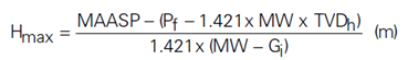
Where:
Hmax = Maximum allowable vertical height of the influx (m)
Gi = Influx gradient (SG)
Pf = Formation pore pressure (psi)
TVDh = Vertical depth of open hole (bit) (m)
Calculate the maximum allowable influx volume that Hmax corresponds to at the initial shut-in conditions.
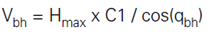
Where:
Vbh = Maximum allowable influx volume at initial shut-in condition (bbl)
C1 = Annular capacity around BHA (bbl/m)
qbh = Hole angle in the bottom hole section (degree)
(*) If the bottom hole section is horizontal (or above 90 degrees), the hole angle used in the calculation should be the open hole angle immediately above the horizontal section.
The kick tolerance should be the sum of the calculated volume (Vbh) plus the annular volume of the horizontal section.
(*) In cases where Hmax/cos(qbh) is greater than the length of BHA, the maximum allowable volume (Vbh) should be calculated partly based on the annular volume capacity calculation around BHA and partly around drill pipe.
Calculate the maximum allowable influx volume that Hmax corresponds to when the top of the influx is at the open hole weak point.
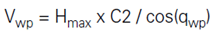
Where:
Vwp Maximum allowable kick influx volume when the top of the influx is at the open hole weak point (bbl)
C2: Annular open hole capacity around drill pipe (bbl/m)
qwp Hole angle in the open hole section below the weak point (degree)
(*) In cases where Hmax/cos (qwp) is greater than the open hole drill pipe length below the weak point, the maximum allowable kick influx volume (Vwp) – should be calculated partly based on the annular open hole capacity around drill pipe and partly around BHA.
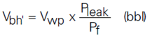
Convert the maximum allowable influx volume at the weak point (Vwp) to what would be at the initial shut-in condition.
Based on Boyle’s law, the maximum allowable influx volume at initial shut-in corresponding to Vwp will be:
The actual kick tolerance should be the smaller of Vbh .
Kick Tolerance Calculation Formulas In Highly deviated Well
Considerations for High-angle and Horizontal Wells
- When considering kick tolerance for the reservoir section, it is often the case that the maximum allowable gas height extends from the open hole bottom to inside the casing / casing liner. This implies that the well can tolerate an infinite volume of gas influx without fracturing the open hole weak point.
- So when the kick influx is circulated to surface, it may fill up the entire annuli of the vertical and low-angle sections and result in very high choke pressures at surface. Therefore, the kick tolerance volume in this case should be determined not only by the formation fracture gradient at the open hole weak point but also by the maximum allowable surface pressure based on the casing burst strength and the pressure ratings of the surface equipment.
Procedures of calculating kick tolerance in highly-deviated wells:
When drilling a high-angle or horizontal well, the following procedure should be used to determine the kick tolerance:
Calculate kick tolerance volume as V1 Formula.
- Determine the maximum allowable surface pressure Psurf based on the casing burst strength and the pressure ratings of the surface equipment (BOP stack, choke manifold, etc). Note its difference with MAASP which is based on the formation fracture gradient at the weak point.
- Calculate the maximum allowable gas height Hmax when the gas influx top has reached the surface:
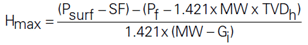
Where:
Gi = Influx gradient (SG)
Pf = Formation pore pressure (psi)
SF = Safety factor mainly determined by the choke operator error margin (psi)
TVDh = Vertical depth of the open hole (bit) (m)
Calculate the kick influx volume that Hmax corresponds to when the gas influx top has reached the surface:
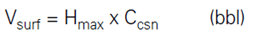
Where:
Vsurf = Maximum allowable influx volume when the influx top reaches the surface (bbl)
Ccsn = Annular capacity in the casing near-surface (bbl/m)
Convert Vsurf to the corresponding volume at the initial shut-in condition:
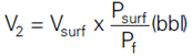
- The actual kick tolerance volume is the smaller of V2 and V1 .
Kick Tolerance Calculations Policy & Considerations
Kick tolerances are to be calculated via formulas as described in the Well Control Manual with the following intensity factors:
- 0.06 sg (0.5 ppg) for development operations.
- 0.12 sg (1.0 ppg) for exploration/appraisal operations applied above the expected formation pressure for well design or current estimated formation pressure whilst drilling.
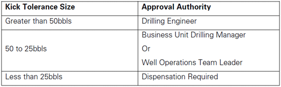
On all wells calculated kick tolerance shall be greater than 25 bbl’s.
Using kick tolerance formulas will always be at the well design stage as it is one of the drivers towards the selection of casing seat (and casing specifications).
Other considerations:
Another key feature of the simple approach to kick tolerance and calculation formulas is that it assumes that the weak point is the previous shoe and that the kick occurs on the bottom.
However, the Drilling Engineer must consider the lithology and pore pressure prognosis to assess the potential for a weaker zone deeper than the shoe, and a kick zone higher than TD. An assumption that the highest risk is from a kick in the zone of highest pore pressure may not be reasonable if, for example, offset data gives high confidence that this is massive mudstone and no permeability exists. In short, the engineer has to assess the reasonably foreseeable risks based on the quality and consistency of data available and design the well accordingly.
Once drilling commences kick tolerance will change if there is a change in hole depth, mud weight, formation pressure, or BHA. Therefore, kick tolerance must be constantly re-evaluated as the well is drilled, not only based on the current condition but also on the future conditions which are expected to occur deeper in the well. Kick tolerance increases in direct proportion to the hydrostatic pressure in the open hole section, with other variables constant.
It is clear that a serious situation would develop if a kick was taken from the high-pressure zone with the mud weight currently in the hole. This might occur if either the pore pressure developed more rapidly than predicted, or if the steady increase in pore pressure was undetected at the surface.
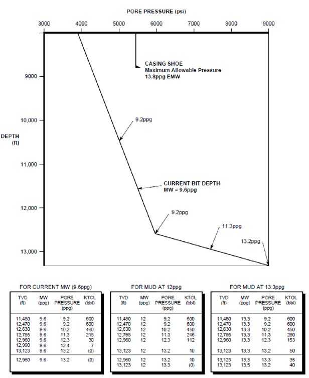
Example For Calculating Kick Tolerance
The figure below shows an example of the type of calculations that should be worked. The kick tolerance figures shown are those that would typically be calculated before a transition zone. As shown, the current bit depth is 3500m and the kick tolerance has been calculated at various intervals across the zone of increasing pore pressure. The kick tolerance has been calculated for the mud weight currently in use, for the maximum mud weight anticipated for the section, and intermediate weight.
From these figures, it is clear that a serious situation would develop if a kick was taken from the high-pressure zone with the mud weight currently in the hole. This might occur if either the pore pressure developed more rapidly than predicted, or if the steady increase in pore pressure was undetected at the surface.
The kick tolerance figures for the intermediate mud weight show that even at this weight, the kick tolerance would be small if the high-pressure zone was unexpectedly encountered.
The kick tolerance is finally calculated at the maximum mud weight. These figures show a final minimum kick tolerance of 50bbl at that mud weight. In general, these figures indicate that drilling should proceed cautiously through the zone of increasing pore pressure. On the basis of these figures, it may be decided to weight up the mud a certain amount before the predicted increase in pressure occurs.
The decisions that are made on the basis of kick tolerance figures such as these will be largely dependent upon the particulars of each situation, including the level of confidence placed in the pore pressure prediction.
Reference
- BP Well Control Manual.
Most operators use 0.12 SG EMW over mud weight as the “kick intensity” factor for exploration wells, while BP Well Control Manual specifies 0.12 SG EMW “kick intensity” factor over estimated pore pressure. Please provide arguments justifying the BP standard against the more popular standard.