The Inside BOP (IBOP) as gray valve is a back-pressure type valve (or float valve) that allows stripping operation using drilling kelly / top drive or running drill pipe into the hole without mudflow upward through the valve. It can be stabbed and made up on the drill pipe only at very low flow rates. The best method is to stab and close the Full-Opening Safety Valve first, then install the Inside BOP if the decision is made to go back into the hole.
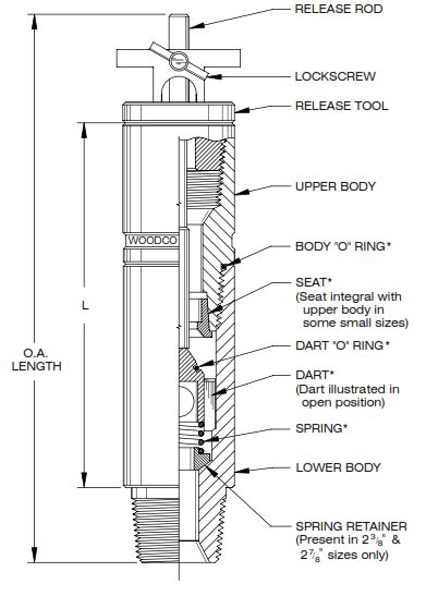
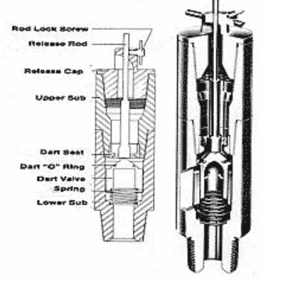
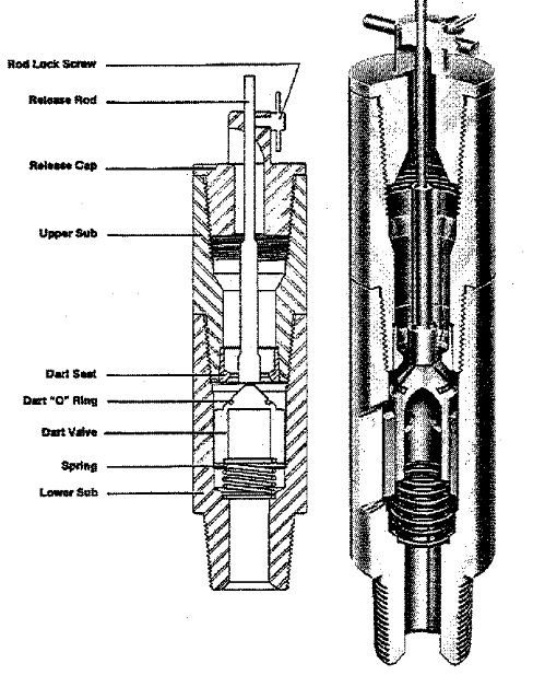
The ‘dart type’ Inside BOP is one of the more widely used tools. The dart is used to hold the tool open, making it possible to install the tool while mud is flowing from the well. The release of the dart permits the valve to close. The upper sub is then removed and an additional drill pipe may be added as desired. The ‘dart type’ Inside BOP is shown in Figure 1
An inside BOP and Full Opening Safety Valve (FOSV) complete with lifting arms must always be available on the drill floor and be open ready for immediate use. If the well starts to flow whilst tripping pipe, the FOSV should be installed, made up, and closed and then shut in the well (Hard Shut in Procedure – Soft Shut in Procedure) and close the BOP stack.
Inside Blowout Preventer Valves
There are several pieces of equipment in addition to the primary blowout prevention equipment that is sometimes necessary to control a kick (kick warning signs). The equipment which furnishes closure inside the drill string is called an “inside” blowout preventer.
A number of devices serve this purpose. The “names” of these devices are often confusing. Below we provided a simple explanation for each kind.
Upper Kelly Valve / Kellycock
The upper kelly valve, or kellycock (Figure A), is installed between the kelly and the swivel and normally has left-hand threads. Because it is installed above the kelly, it is always available. (Note: it is not actually the inside BOP or IBOP but it has the function of inside blowout preventer). The basic purpose of this valve is to isolate the fluid in the drill string from the swivel, rotary hose or standpipe and to prevent leaks or rupture under well conditions. If
the drill pipe pressure exceeds the rating of the rotary hose, closing the valve allows a safe change to higher pressure connections. It also permits the removal of the swivel so that wire lines or tools may be run into a pressurized drill string. The most common design has a flapper as shown in Figure A. The other design is a full open ball similar to the lower kelly valve.
The upper kelly valve should have a WP rating equal to or greater than that of the blowout preventer assembly being used and should have an inside opening equal to that of the kelly. To operate this valve, a special wrench is required and should be kept in an accessible place on the rig floor.
Lower Kelly Valve / Lower Kellycock
A lower kelly valve (Figure B) is sometimes called a lower kellycock. It is installed on the lower end of the kelly, and is used when the upper kelly valve is damaged or not easily accessible. If the kill pressures ( check weight and wait method – Driller’s method) approach the rotary hose ratings, this valve is closed, the kelly broke out and set back and the cement standpipe hose is connected via a circulating head to the lower kelly valve.
Safety Valve
During trips on rigs with kelly drive, the kelly and both upper and lower kelly valves are stored in the rat hole. For this reason, another valve, identical to the lower kelly valve, is stored close by so it can be quickly installed on the drill pipe during a trip should a kick occur. When used in this manner, it is called a safety valve.
If a tapered drill string is being used, then a safety valve for each size pipe and crossovers to drill collar connections must be available on the rig floor.
All of these kelly and safety valves should be operated at the beginning of each tour. They should be tested when the BOP is tested (BOP Pressure & Function Tests) and the pressure should be applied in the direction pressure would be felt should the well be closed.
Upper Remote Safety Valve and Lower Safety Valve (Top Drive IBOP)
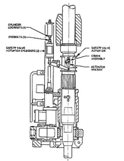
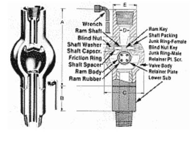
The upper and lower safety valves on top drive systems are connected together (same function as IBOP). They are a ball-type design. Both are very likely to be inaccessible should a kick occur during drilling operations, so the upper valve is remotely operated as shown in Figure C.
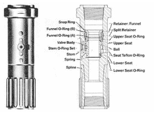
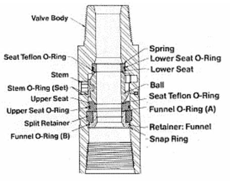
The body on this particular design of top drive ibop is splined to accommodate the pipe handler system. Some top drive units use a different kind of torquing mechanism which does not require a special O.D. profile on the upper safety valve. In these cases, the upper and lower safety valves may be identical except that the upper is fitted with a remote actuator crank and the lower is plain manual operated. Figure C illustrates the two valves installed in the top drive assembly. Figure D1 & Figure D2 show these two valves separated.
During trips with the top drive system, the swivel and safety valves ibop are not set back but rather are hoisted with the drill string. Should a kick occur during the trip, the safety valves are immediately connected to the drill string, and the upper valve remotely closed. There is no need to have another safety valve on standby as with kelly drive operations.
Inside BOP (IBOP Valve)
Although all valves that secure the drill string bore are “inside” BOPs, the check valves discussed in the following paragraphs are the only ones commonly called “inside BOPs” (Figure E).
They are normally used for stripping in the hole under pressure when a kick occurs off the bottom during a trip as all these valves are check valves closing with flow from below but free to pump through from above.
By utilizing a special tool, the inside BOP or check valve may be kept open to permit stabbing into the drill string when the well is kicking. Once made up in the drill string, the tool is released and the check valve closes. However, check valves are more difficult to stab against drill pipe flow than are full open ball valves. Therefore, the full open safety valve should be installed first and then the “inside” BOP (check valve) installed if it is necessary to strip back in the hole.
Three types of inside BOPs can be used:
- Gray valve
- Drop-in check valve
- Float sub (bit sub) (Drilling Subs)
Presently there are alternative valves on the market which have an unrestricted bore with the (flapper) valve retained by a sleeve.
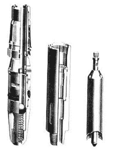
Gray Valve
The Inside BOP Gray valve is stored on the rig floor and is kept in the open position by a valve rod and a valve release screw.
If the well starts flowing a kick (check kick warning signs) while tripping pipe the drill pipe must be closed in first. When there is a light flow the Gray valve can be installed directly on the drill pipe. However, with strong backflow, the force of the flowing mud can be so strong that it is not possible to install the Gray valve due to its obstructed bore. In such a situation a kellycock, which has full bore passage, has to be installed first. After the kellycock is made up and closed, the annular preventer is closed. If it is decided to do pipe stripping operations into the hole the Gray valve will be installed. The valve release screw is undone and the spring will close the valve. The locking sub is then removed and the kellycock opened.
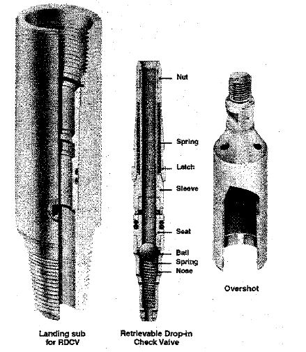
Drop-In Check Valve / Dart Type Valves
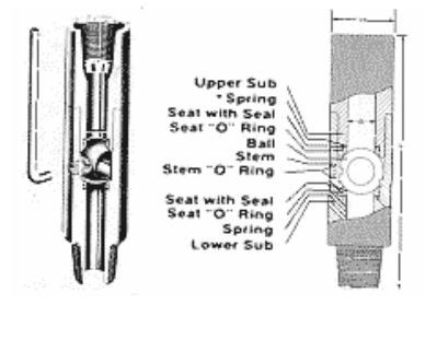
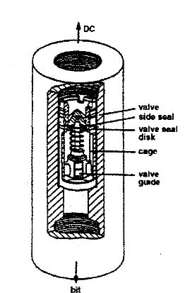
Another type inside BOP is the pump down or drop-in type which requires a special sub near or in the bottom hole assembly of the drill string. These inside BOPs are often used in stripping operations and particularly stripping “out” operations. Some are wireline retrievable. Figure F shows one type of drop-in check valve.
Bit Float
A bit float (Figure G1 & Figure G2) may be considered an “inside” preventer.
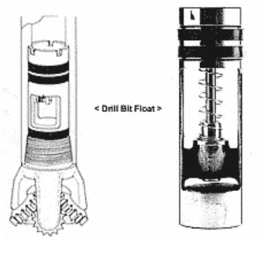
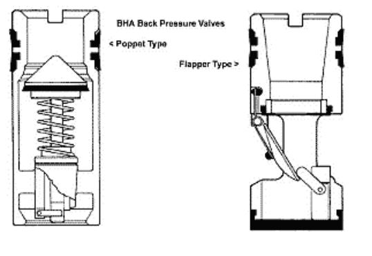
It is basically a flapper or poppet type check valve that is installed in the oilfield drilling bit sub to prevent backflow during connections; however, it is subjected to severe wear by the drilling mud and may not function when needed. A common practice is to use a slotted flapper. This reduces backflow to a minimum, yet allows stabilized shut-in pipe pressure (check hard shut in procedure – soft shut in procedure) to be easily read should the well kick.
Most operators discontinue the use of bit floats after setting surface casing. Kicks are more likely to occur below the surface casing and the bit float might interfere with a good stabilized closed in drill pipe pressure reading. Bit floats are most useful in top hole drilling where backflow during connections is more likely due to imbalanced annular fluid density.
How To Use Inside BOP (IBOP Valve) In Case Of Well Control Issue
To install the IBOP during well backflow conditions:
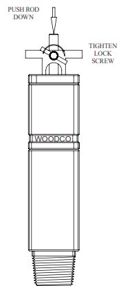
Always, have the release tool in place and use the release rod to push the dart into full open position (dart pushed down as far as it will go, see Figure 2). Hold the dart in open position by tightening the lock screw (See Figure 4 for illustration of parts and their relationship to one another).
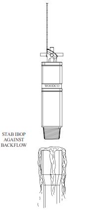
With the dart held in the open position, stab the IBOP into the open pipe connection during backflow. (See Figure 3).
Make up the IBOP like any tool joint connection and tighten with tongs.
Stop any backflow through the pipe by loosening the lockscrew and allowing the dart to seat and close the IBOP Valve.
After closure, remove the complete release tool and connect another joint of pipe into the top of the IBOP.
The IBOP can function as part of the pipe string as long as well conditions require.
Inside BOP Conclusion:
- The inside BOP is a non-return valve contained in a sub that can be made up in the drill string.
- A ‘Gray-type’ inside BOP NRV with the appropriate connections for the drill string in use, shall be on the drill floor at all times. It shall be ready for immediate use.
- It is always made up above the FOSV when stripping is required or may be stabbed directly onto the drill string in place of the FOSV.
- Practical considerations for use are similar to the FOSV with the exception that once it is installed there is no longer wireline access to the drill string below it, neither can pump-down devices be used.
- The Full Opening Safety Valve (stab-in valve) and the inside BOP (Gray valve) must be available on the rig floor at all times. In addition to routine inspection, it must be confirmed prior to any operation that:
- They are in the open position
- The FOSV is full bore and does not present a restriction to drop-in darts or W/L tools
- They can be crossed-over to any pipe in the string
- They can be easily man-handled.
- The hydraulically operated IBOP valve (kellycock) of a top drive should be function tested every day.