Cementing head is a manifold system that is installed on the top of the casing which allows the cement slurry to be pumped from the cement unit down any of the types of casing string. The cement head is also used for releasing the top and bottom cement plugs.
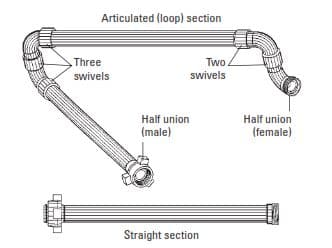
A “cement head” is screwed into the top casing collar or landing joint, depending on the type of casing cementing job. The discharge side of the downhole pump and the cement head are connected by a series of articulated or straight sections of high-pressure steel pipe, also known as “treating iron” (Fig. 2).
Cementing Head Application
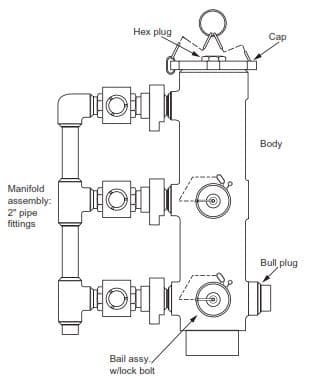
The cement head provides the connection between the discharge line from the cement unit and the top of the casing (Figure 1). This piece of equipment is designed to hold the cement plugs used in the conventional primary cementing job. The cement head makes it possible to release the bottom cementing plug, mix and pump down the calculated cement slurry volume, release the top plug and displace the cement without making or breaking the connection to the top of the casing. For ease of operation, the cement head should be installed as close to rig floor level as possible. The cement jobs will be unsuccessful if the cementing plugs are installed in the correct sequence or are not released from the cementing head.
Mud is normally used to displace the cement slurry. The cement pumps or the rig mud pumps may be used for the displacement. It is recommended that the cement slurry be displaced at as high a rate as possible. High rate displacement will aid efficient mud displacement. It is highly unlikely that it will be possible to achieve turbulence in the cement slurry since it is so viscous and has such a high density (cement properties). However, it may be possible to generate turbulence in the spacer and this will result in a more efficient displacement of the mud.
Cementing Head Types
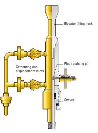
Single Plug Cement Head
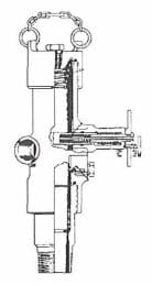
Just before pumping the cement, the bottom plug is inserted through the container, followed by the top plug, which rests on the releasing pin. When cement additives mixing has been completed, the top plug is released before displacement starts. The downward movement of the plug into the casing is indicated by the lever mechanism below the releasing pin. Another method is to insert a radioactive nail in the plug and monitor its movement with a Geiger counter.
Double Plug Cement Head
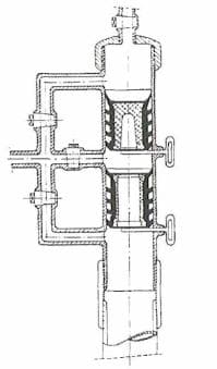
Heads capable of storing multiple plugs are preferred over those just carrying single plugs for operational convenience, as the use of more than one plug requires the opening of the head to insert a second (or even a third) plug after circulating the drilling fluid and launching the bottom plug. This allows not only the build-up of gels in the annulus, having an adverse effect on fluid displacement efficiency, but also cement-free fall. The risk of sticking the casing (pipe sticking) is also increased if reciprocation is stopped to allow the insertion of the additional plug (or two).
Subsurface Plug Release Systems
These are designed for use with subsea wellheads. The bottom and top cementing plugs are positioned in the casing just below the casing hanger, which is run to the seabed on drill pipe. The cement head stores the bottom plug launching ball and the top plug wiper dart and operates in the same way as a double plug head, offering circulation below the plugs or after them as required during the job.
Casing Liner Cementing Head
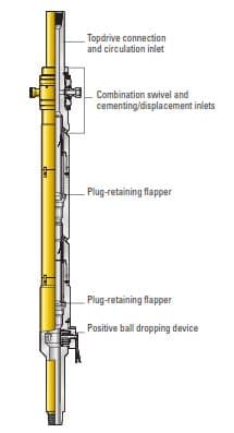
The surface equipment is located on the drilling rig floor. It connects the running string to the block of the rig and connects the displacement, circulation, and cementing unit lines to the drill string. The surface equipment holds the displacement plugs and setting balls for hydraulically operated tools downhole. There are two types of cementing heads for running casing liners (Liner running procedures). The first (Fig. 5) is used for conventional drilling rigs and the other is used for drilling rigs that operate with a top drive system (Fig. 6). This equipment allows total control of the weight set on the liner, because the surface cementing equipment carries the string weight at all times during the cementing and liner-installation operations.
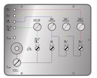
In some parts of the world, local regulations require the cementing heads to be operated directly from the rig floor. For these areas, a remotely controlled pneumatic version of the cementing head is used. The remote-control panel is shown in Fig. 7.
Pneumatically operated surface equipment is also used in areas where rotating liners are run on a regular basis. With conventional systems, it is a safety standard to stop the rotation when the displacement plugs or setting balls are being launched. Resuming liner rotation after stopping may be difficult or impossible. The pneumatic design permits continuous rotation of the liner, enhancing the safety and efficiency of the liner-cementing operation.
Subsea Cementing Head
Brandt et al. (1998) introduced a two-plug launching system (Fig. 8) adapted to subsea operations from its original fixed installation concept (Lavaure and Galiana, 1991). This cementing head offers enhanced reliability because of a simpler cement-plug design in which the plugs are isolated in their container from the main fluid flow. Plugs are released from the subsea tool without physical contact between the darts and the plugs, avoiding dart-to-plug or ball-to-plug sealing problems.
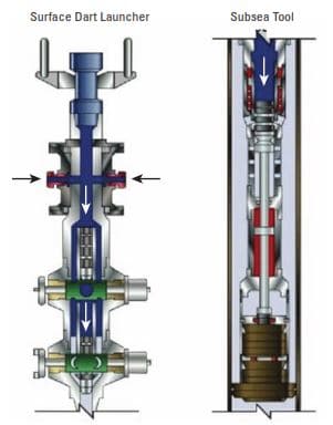
Dart launcher
A surface dart launcher contains two identical darts launched during cementing (Cementing in drilling). Darts are remotely released, reducing rig time and increasing the safety of the operation. Using darts instead of a free-fall ball helps prevent contamination, provides positive fluid displacement, wipes the drill pipe clean, and saves time. Uninterrupted high pump rates improve mud removal (mud conditioning) because the fluid is neither resting nor allowed to gel at any time.
The darts release casing wiper plugs when they reach the subsea tool. Because the dart launcher is modular, adding segments is easy. This increases the number of darts that can be launched.
Subsea tool
After dart launch, mud flows down the drill pipe, through the sliding sleeve of the subsea tool, and out of the orifices. The dart lands on a rod and continued pumping forces the dart and rod down, pushing the plug out of a basket. A spring retracts the sliding sleeve, allowing complete, unobstructed flow through orifices.
A pressure differential resists rapid rod motion and stops rod movement after the plug releases. Combined with plug friction, this pressure differential increases pumping pressure and provides a positive indication at the surface of plug launch. Physical spacers prevent the plugs from sticking and are retrieved with the tool. The downhole subsea tool encases the plugs inside a container, eliminating difficulties associated with pumping fluids through the inside of plugs. Simplified plug design allows use of high-performance, but easily drillable plugs.
The dart launcher has a high-pressure rating, and the plugs have a high collapse resistance; therefore, this system allows the operator to conduct a casing pressure test immediately upon bumping the plug. This saves rig time and reduces the risk of creating a micro annulus or damaging the cement sheath—a danger when this operation is carried out at a later stage (Carré et al., 2002).
Conclusion
The purpose of the plug container or cementing head is:
- To permit the cement plugs to be released into the casing at the proper moment with- out seriously interrupting pumping so minimising the risk of delay and mishap.
- To provide a connection between cement pumping equipment and casing which can be closed to allow the cement lines to be pressure tested.
- To permit pressure being held on casing after cementing to back up the floating equipment.