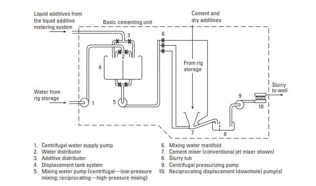
Figure A is a schematic flow diagram of cement-slurry preparation that indicates the steps performed at the central storage location and at the wellsite. Each function in the flow diagram also represents a major piece of equipment. Some functions may be combined into a multipurpose “cementing unit.”
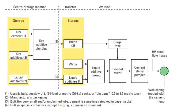
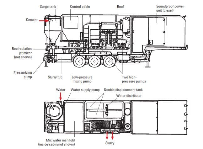
For economic reasons, a cementing unit as one of the drilling rig components is designed to meet the requirements (including road regulations) of as many locations as possible. In Europe, for example, the required specifications vary from one country to another, and the unit must conform to the most stringent regulations. In addition, soundproofing is more frequently demanded because of the proximity of wells to residential areas (Fig. 1).
Cementing Unit Components
Cementing Pump
We have previously discussed it before here in cementing pump article.
Storage Bulk Tanks
Pneumatic bulk trucks or trailers transport neat or preblended dry cement to the wellsite from the central storage and blending plant. Neat cement can also arrive directly from the cement mill. The material is then transferred pneumatically to transportable tanks that are either brought to the rig site for the cement job or are a permanent part of the drilling rig equipment. Such tanks are similar to those used at central storage locations, but their dimensions allow transport on standard or specially designed (with a built-in hydraulic laying/raising system) trailers. When empty, the tanks must not exceed the weight limits specified by various countries.
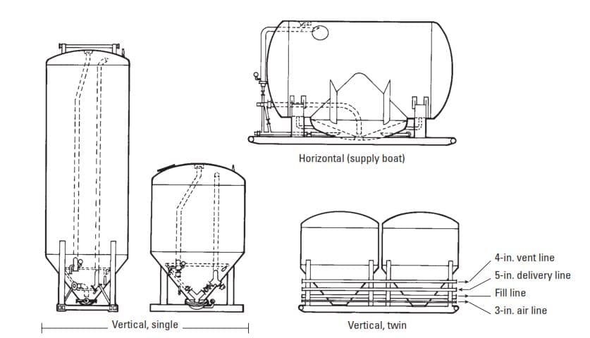
A large variety of storage tanks for road travel exists within two principal categories
- atmospheric
- pressurized.
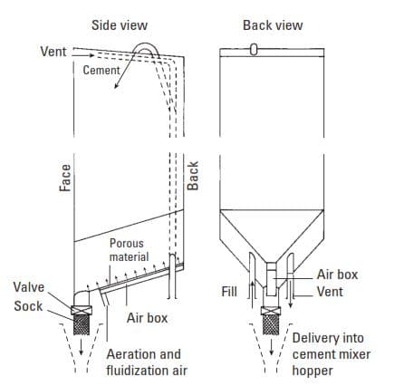
The atmospheric tank is always operated in a vertical position. Air at low pressure (about 3 psi [0.2 bar]) is blown into a gutter fixed to the slanted bottom of the tank. The roof of the gutter is made of a porous material. The air passes through the porous partition and fluidizes the cement blend. The cement blend glides along the slanted bottom to a chute gate and then to the hopper of a slurry mixing system. As illustrated in Fig. 2, atmospheric tanks are made in the shape of a parallelepiped.
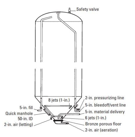
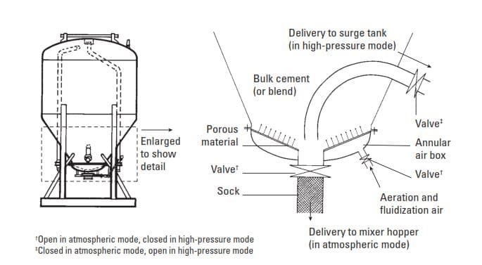
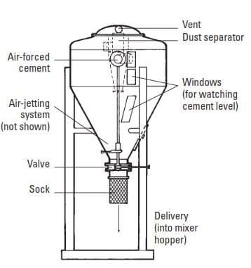
Pressurized tanks use air at about 44-psi [3-bar] pressure and can operate horizontally or vertically. Figure 3 is a schematic diagram of a typical unit. As shown in Fig. 4, the vertical tanks are generally cylindroconical in shape, while horizontal models are more complex. In the first stage, pressure-reduced air is blown from the bottom through the mass of cement for aeration and fluidization. Then air at 44 psi [3 bar] is injected into the tank, and the cement flows out through a discharge line to a surge tank, which feeds the cement mixer. For versatility, some vertical pressurized tanks are also equipped to release the cement directly to a hopper at atmospheric pressure (Fig. 5).
The bulk trailers are sometimes used for additional storage. Indeed, they can serve all storage needs on the rig site, provided they are equipped with their own surge tanks, described later.
Displacement Tank System
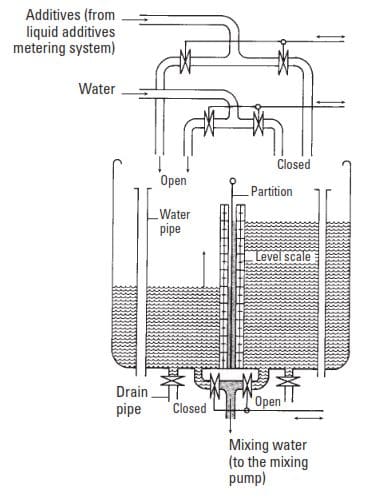
Contrary to what one might think, the simple method of employing a flowmeter is not used for water metering. A set of twin 10-bbl (or sometimes 20-bbl) tanks is preferred. A “displacement tank” (Fig. 6), which is divided equally by a partition, is also used. Both sides of the partitioned tank are filled with mix water from the rig storage. If the casing cementing job (cementing in drilling) is offshore, the freshwater or seawater distribution system is used. Each batch of mix water is then used successively to feed the cement mixer. The cement additives may be preblended with the water in the storage tanks or may be blended while the water is passing through the displacement tank. In the second case, a liquid-additive metering system (described later) is required.
For precise placement of the slurry in the wellbore, the volume of the displacement fluid must be accurately calculated (Cementing Calculations). After the cement slurry has passed through the mixing system, the displacement fluid usually passes through the displacement tanks for volume measurement and is pumped by the cementing unit instead of the rig’s mud pumps.
Liquid additive storage and mixing In Cementing Unit
The simplest method of mixing liquid additives (and dry additives at less than 3% by weight of cement) with water consists of pouring the required amount of each additive into a tank of water. One should measure the additives and water accurately to obtain the correct concentration; the preparation of a slight excess of solution is also advisable. The mixing can be achieved with a paddle mixer, circulation pump, jetting system, or a combination of these.
The premix method has several disadvantages. Premixing requires an extra tank, which must be clean and sufficiently large. Extra tanks are not always available, and sufficient space to accommodate them may not exist on the rig site, especially offshore rigs. If the job is canceled or postponed, the costly solution may have to be thrown away. Also, if a larger-than-expected volume of slurry becomes necessary during the job, the volume of the premixed additive solution may be inadequate. Thus, methods that allow continuous (“on-the-fly”) mixing are often preferred. On-the-fly methods employ a semimanual or automatic metering system that delivers the correct amount of additives to each side of the displacement tank.
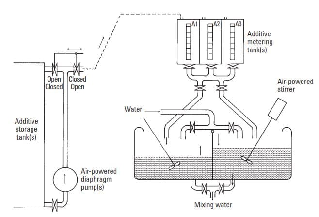
Liquid additive metering system with metering tanks
All liquid-additive metering systems consist of two principal parts a storage and transfer unit and a metering unit.
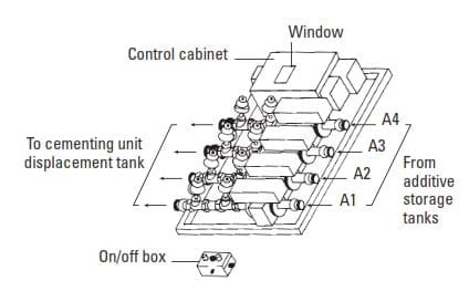
Liquid-additive metering system without metering tanks
In the liquid-additive-system metering rack (Fig. 8), the operator depresses a button to initiate the delivery. The metering rack behaves as four or more “smart valves,” installed between the additive pumps and the displacement tanks. The valves are controlled by a microcomputer using data from electromagnetic flowmeters.
Surge tanks
For smooth cement mixer operation, the supply of cement (or blend) should be steady, and the pressure at the mixer bowl should remain constant. The bulk cement is moved from the storage tank toward the cement mixer, driven by the differential pressure created between the tank and the end of the line. If the line is longer than approximately 23 ft [7 m], the cement tends to separate from the conveying air into slugs, creating pulsating flow. To smooth the flow and allow for operational requirements, such as changing from one storage tank to another, a surge tank is used.
Cement Mixer
The cement mixer is a device in which a flow of pressurized water (possibly containing additives) meets a flow of cement (possibly containing additives), and a cement slurry is formed at a prescribed rate. Several types of mixing systems exist such as:
- Conventional jet mixer
- Recirculation jet mixer
- Recirculation mixer without conventional jets
- Cement mixing units
Conventional Jet Mixer
The conventional jet mixer consists of a hopper, a mixing bowl, a discharge gooseneck, and a slurry tub. The maximum slurry-generating capacity of the conventional jet mixer, evaluated in rate of dry material, is slightly higher than 2,200 lbm/min (1 SI ton/min). Figure 10 shows a configuration for sacked cement, and a system for pneumatically delivered cement is illustrated in Fig. 11.
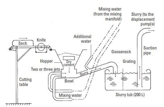
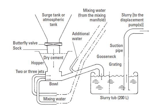
The cement is delivered to the hopper. The water is injected into the bowl through jets for mixing with the cement and into the gooseneck for adjusting the slurry density (cement properties). The jets are chosen according to the operating pressure, slurry fabrication rate, and type of dry materials. The movement of cement down through the hopper is assisted by the high-pressure flow of water through the jets. The resulting pressure drop pulls the dry cement into the stream of water. To reinforce this effect, the gooseneck can be given a venturi tube profile. Further along at the gooseneck, turbulent flow mixes the cement particles with the water, and the result is a cement slurry.
The slurry density is adjusted by using the bypass system to change the water-to-cement ratio. As the bypass is opened, the suction effect decreases and reduces the amount of cement drawn out of the hopper. At the same time, the water bypassing the jets enters the slurry. The combined effect is a decrease in slurry density. Conversely, if the bypass is closed, the density increases.
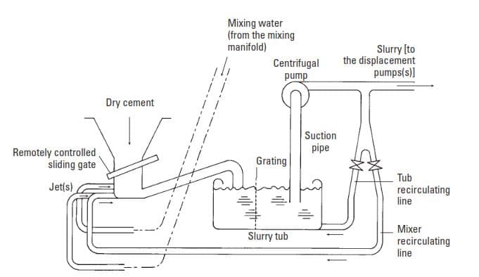
Recirculation jet mixer
The recirculation jet mixer differs from the conventional type in several ways.
- A remotely controlled sliding gate is present between the hopper and the bowl.
- The slurry density is adjusted by operating the sliding gate.
- The slurry is removed from the slurry tub by a recirculation jet, fed by a centrifugal pump. The centrifugal pump force feeds the displacement pumps and recirculates some slurry through the mixing system.
- Water is always injected ahead of the recirculation jet. Recirculation through the mixer heart and the tub improves the homogeneity and rheology of the slurry. Adjustment of the slurry density is also easier.
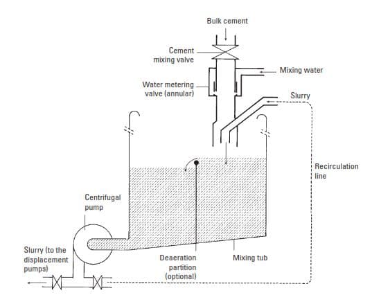
Recirculation mixer without conventional jets
They all consist of the following.
- A sophisticated metering system to mix cement with water and a device to mix the resulting slurry with previously mixed slurry from the mixing tub
- A centrifugal pump or similar device (located at the bottom of the tub) to improve the initial mixing by shearing, ensure recirculation through the mixer, and feed pressurized slurry to the downhole pump
- A mixing tub that can be divided into two sections, each of which can be equipped with a stirrer to improve mixing, allowing a film-like flow over the common partition that assists the release of entrapped air
Depending on the model, the density of the slurry is remotely controlled by metering the cement and/or water. The water rate is usually kept constant, and the slurry density is controlled by altering the rate at which cement is delivered to the mixer. Normally, the cement is transferred directly from a pressurized tank without passing through a surge tank.
Cementing Unit Types
The various components of cementing units, which fabricate and inject the cement slurry, have been described individually in the above sections. Figure 14 illustrates the combination of the components to assemble a basic cementing unit. A variety of configurations and compositions exists, tailored to the type of rig to be serviced and the redundancy, versatility, and mobility required. The various configurations are described below, according to the type of rig to be serviced.
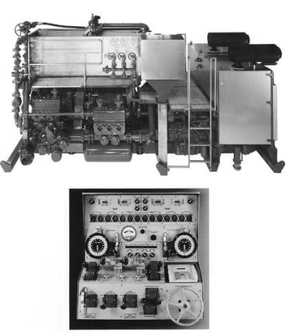
Skid-mounted units:
Illustrated in Fig. 15, skid-mounted units are most applicable to isolated land rigs, offshore rigs, cementing barges (lakes and rivers), and open-sea cementing vessels.
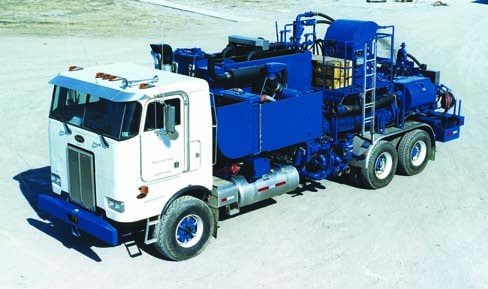
Truck Mounted Units:
Shown in Fig. 16, such units are suitable for almost any land rig. However, the chassis must be adapted to the type of surface upon which the unit will travel. The “standard” unit is designed to travel on roads and must conform to local road regulations. The “off-road” unit is built for more difficult terrain. The “desert” unit can be driven over soft surfaces, even sand dunes.
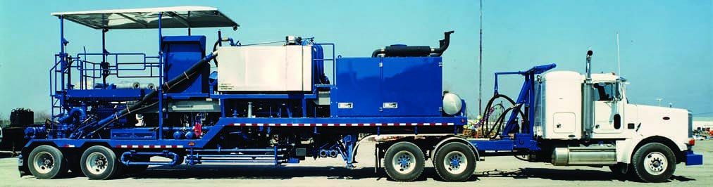
Semitrailer-mounted units:
Like the truck-mounted units, semitrailer-mounted units as shown in Fig. 17 are appropriate for almost any land rig. They can be drawn by many types of tractors, providing a logistical advantage. A heavy tractor-drawn unit with five axles has a better weight distribution ability than the corresponding truck with only three. The maximum authorized payload is greater than that of the truck, which allows the loading of more equipment on the same chassis.
Helicopter Units:
Helicopter units are intended for rigs totally inaccessible by land or water. The units, the mixing equipment, and the cement silos are designed to be transported by helicopter. They can be dismantled into smaller components, incorporating lifting frames, and are often made of lighter materials to reduce weight. Traditionally, a cementing unit contains two of each vital item. This redundancy is necessary because a well can be severely damaged or lost if it becomes impossible to complete a job after it has commenced. The extra equipment serves as an “insurance policy” to protect the operator’s investment.
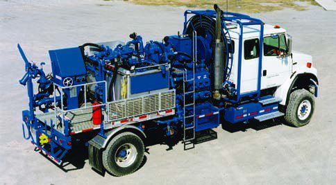
Single Pump Cementing Unit
However, single-pump units now exist. One such unit is shown in Fig 18. This unit provides a cost-efficient solution for less-critical, lower-pressure well casing jobs. High-pressure treating iron is replaced with a flexible hose for faster wellsite rig-up.
Safety Requirements For Cementing Units
Cementing-unit designs are developed with special attention to safety and environmental requirements. Environmental release of wastes (liquid or dry chemicals, cement slurries, or pump or engine oil spillages) is prevented by better equipment design and the use of recovery receptacles.
The safety requirements with which the equipment should comply depend upon the location and are especially dependent upon possible sources of flammable or explosive gases. Whenever the unit can be placed more than 98 ft [30 m] away from the well (as on most land rig sites) there are no special requirements. Standard equipment can often be used without modification. This distance condition is often difficult to satisfy on offshore rigs, where every compartment or deck location is classified according to the potential risk of explosion or fire. The classification is made by official regulatory bodies according to standards that may vary slightly from one country to another; however, operators usually adhere to the most stringent regulations.
For example, the following is a summary of the Det Norske Veritas (DNV) requirements for diesel engines to be located in a hazardous area (Oil Rig Hazards), classified as “Zone 2,” in which an explosive gas mixture may exist for a short time only under abnormal conditions. Diesel engines are banished from Zones 0 and 1, which are more sensitive areas. The DNV is the Norwegian certification body, and its standards serve as a reference in the North Sea.
- Special water-cooled manifold rated to cool exhaust gas to 200°C (392°F) maximum, and with a surface temperature not exceeding 200°C at any point.
- Oversized radiator.
- Inlet air combustion, slam-shut valve.
- Inlet air flame trap.
- Exhaust gas spark arrestor, DNV type approved.
- Overspeed valve, which closes the engine blower flapper valve when speed exceeds the normal maximum by 10%.
- High-water-coolant temperature valve, which shuts down the engine when water temperature exceeds 95°C (204°F). Fuel rack actuated.
- Low-water-coolant level valve, which shuts down the engine.
- High-exhaust-gas temperature valve, which shuts down the engine when the gas temperature exceeds 200°C.
- Special control panel.
Diesel engines must often be adapted further to meet fire-protection standards. The equipment required to adapt an engine is sophisticated, entirely made of highquality stainless steel, and bulky. It is extremely expensive. Electric motors for Zone 2 areas are typically confined in a closed shelter, which is pressurized with air taken from a safe area. An overpressure is maintained so that no gas from the hazardous area can enter the shelter. When a cementing unit is to be operated offshore in a nonhazardous area, the drilling and service oil and gas companies often opt for “protected” diesel engines, which provide increased security at a more reasonable cost. Following is a list of the devices that should be installed on a standard diesel engine to ensure this protection.
- Overspeed valve, which closes the engine blower flapper valve when speed exceeds the normal maximum by 10%.
- High-water-coolant temperature valve, which shuts down the engine when water temperature exceeds 95°C. Fuel rack actuated.
- Low-oil-pressure valve, which shuts down the engine when engine oil pressure is below a value to be settled with the manufacturer. Fuel rack actuated.
- High-oil-temperature valve, which shuts down the engine when oil temperature exceeds 130°C (266°F). Fuel rack actuated.
- Special control panel.
georginourt