Coiled tubing fatigue is the progressive damage caused by repeated loading of the tubing. During normal deployment, the reel and guide arch repeatedly bend and straighten the tube beyond its elastic range. Internal pressure, tubing geometry and the history of each section influence how quickly that damage develops [1, 2].
Consequently, two strings with the same outside diameter and running footage can have different remaining working lives. Even two sections of the same string can have very different histories. A useful assessment therefore follows the material through each surface bend and records the pressure during that movement [1, 2].
This guide explains the mechanism, applications, influencing factors, rules of thumb and limitations. It also includes an original bending-strain example. For the equipment arrangement behind the discussion, see the coiled tubing complete guide.
What Is Coiled Tubing Fatigue?
A steel CT string is already curved when stored on its reel. As a section leaves the reel, crosses the guide arch and enters the injector, its curvature changes. Retrieval reverses these changes. The resulting plastic deformation accumulates damage and can eventually produce cracks through the tubing wall [1, 2].
The references describe this severe repeated plastic bending as low-cycle or ultralow-cycle fatigue. However, those labels do not provide an allowable trip count. Actual performance depends on the material, pressure, geometry, condition and sequence of loading [1, 2].
Fatigue life also differs from static load capacity. For example, a tube may satisfy a particular pressure or tension calculation while having an unfavorable fatigue history. Conversely, a modest modeled fatigue percentage does not establish acceptable collapse resistance, wall thickness or surface condition. Both questions require assessment [1, 2].
Six Bending Events During One Complete Trip
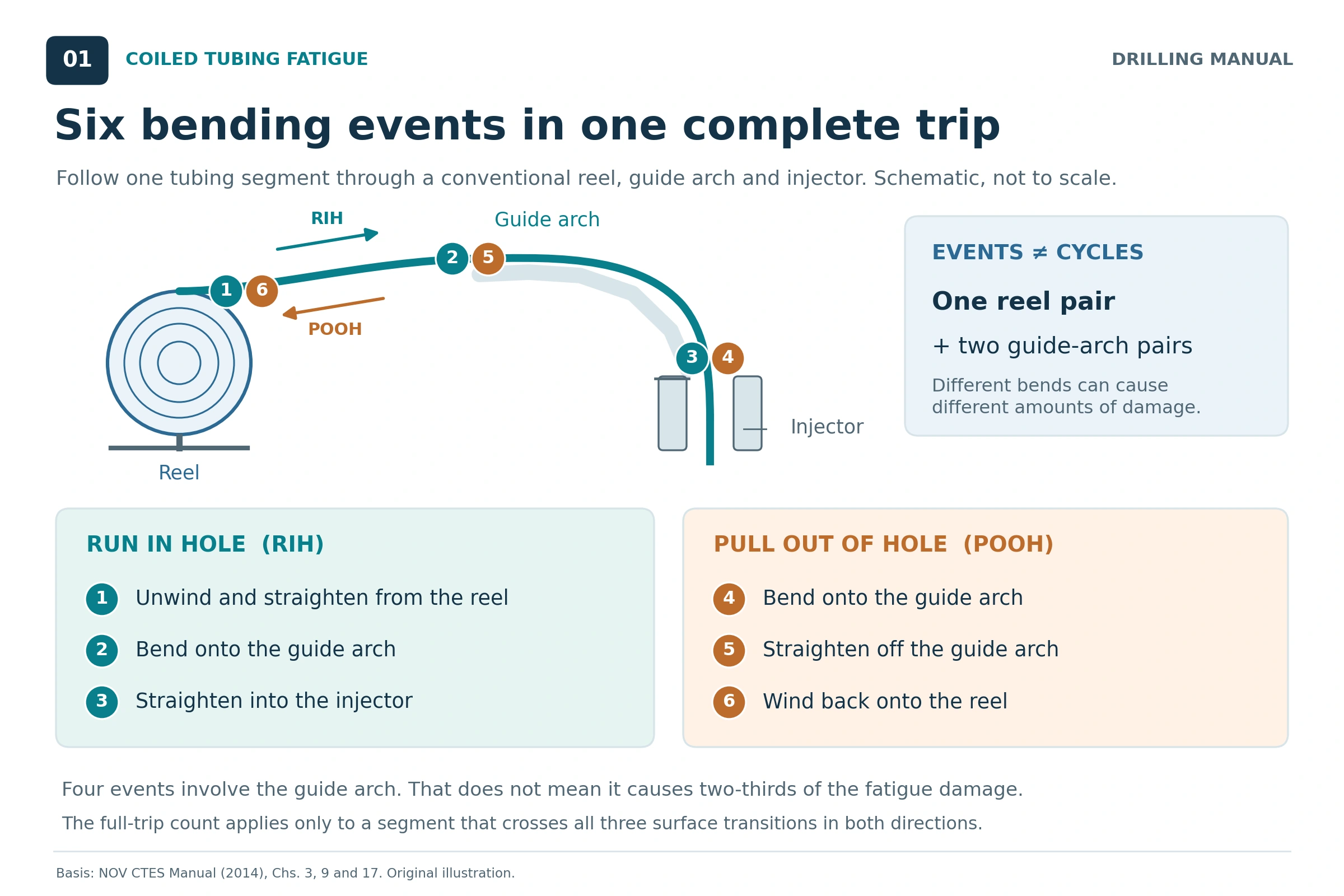
Consider one material section that travels from the reel into the well and returns along the same conventional equipment path. The NOV CTES manual identifies six changes between curved and straight configurations [1].
| Event | Direction | Change experienced by the section |
|---|---|---|
| 1 | Running in | Unwinds and straightens from the reel |
| 2 | Running in | Bends onto the guide arch |
| 3 | Running in | Straightens before entering the injector |
| 4 | Pulling out | Bends onto the guide arch |
| 5 | Pulling out | Straightens as it leaves the arch |
| 6 | Pulling out | Bends back onto the reel |
Why Six Events Are Not Six Complete Cycles
The SPE handbook pairs two events of equivalent strain magnitude into one bend cycle. Under that convention, a complete trip contains one reel cycle and two guide-arch cycles. Therefore, six events must not be entered as six complete cycles in a system using this definition [2].
Furthermore, equal event counts do not imply equal damage. Reel and arch radii may differ, while pressure can change between deployment and retrieval. Although four events involve the guide arch, that does not assign two-thirds of the fatigue damage to the arch [1, 2].
A short stroke may carry a section across only part of the surface path. As a result, the six-event description applies only to a section completing the entire trip. Consequently, actual event tracking needs the surface equipment geometry and the recorded tubing movement [1, 2].
Coiled Tubing Fatigue Calculations: Bending Strain
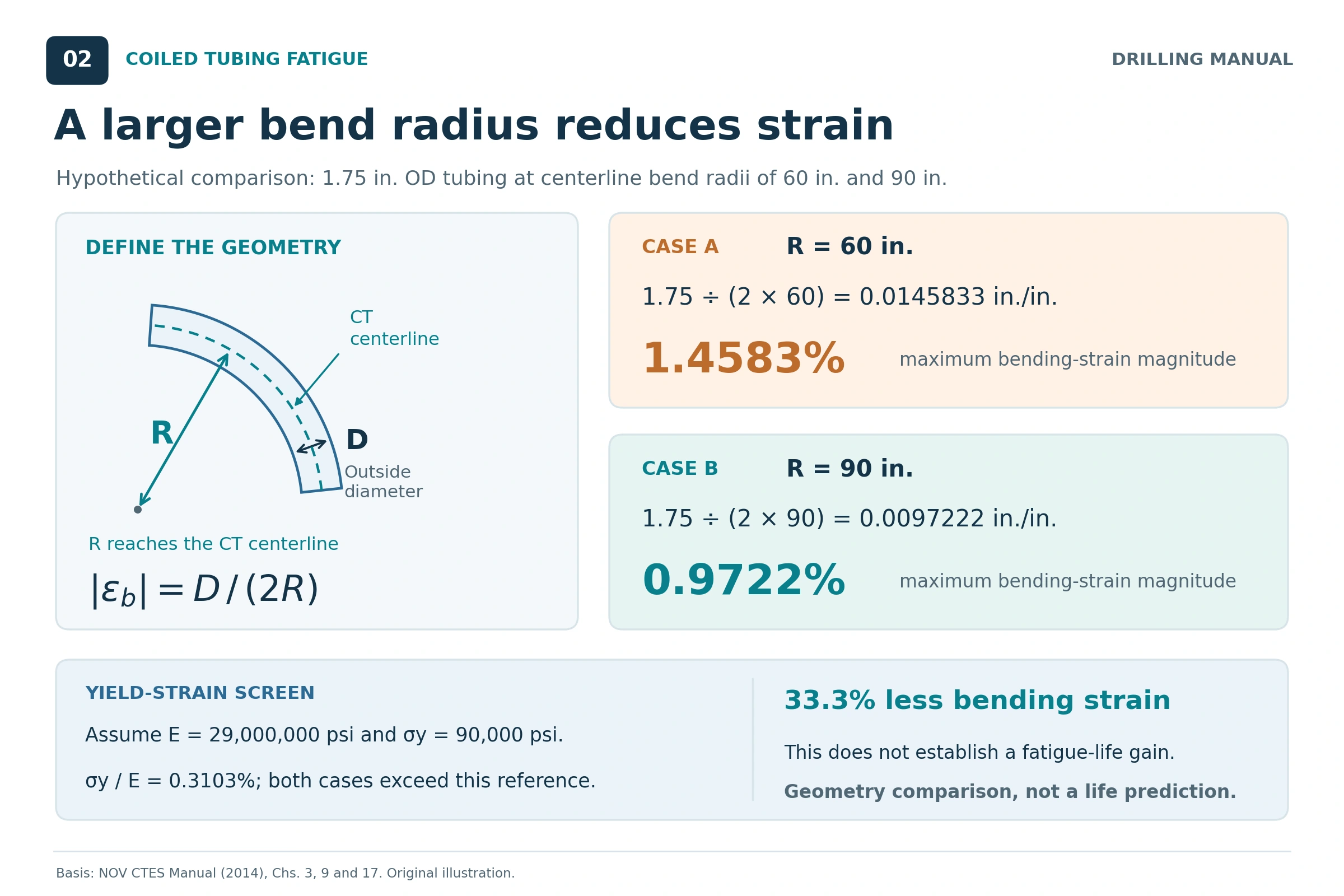
The simplest useful calculation describes the strain imposed by curvature. NOV CTES gives the bending-strain relationship as the tube radius divided by the bend radius. Written using outside diameter, the same relationship becomes [1]:
εb = r / R = Do / (2R)
Here, εb is the maximum longitudinal bending-strain magnitude, Do is the tubing outside diameter, and r = Do/2. Both dimensions must use the same length unit. Therefore, the result is dimensionless; multiply it by 100 to express percent strain [1].
Geometry and Radius Convention
For this geometric calculation, R is the radius of the curved tubing centerline. Imagine a circular tube bent into an arc without changing its cross section. The outermost fiber lies r farther from the bend center than the centerline. Its additional length, divided by the centerline length, is r/R.
This radius convention is essential. A reel diameter, reel-core surface radius or guide-arch contact radius is not automatically the same dimension. For example, the centerline of tubing wrapped directly around a circular core lies one tube radius outside the core surface. Moreover, additional winding layers change its location further.
Therefore, identify the actual tubing path before applying the equation. Use the relevant layer and equipment dimensions from the coiled tubing reel. The example below supplies centerline radii directly, so no equipment-radius conversion is needed.
Comparing Bending Strain With Initial Yield Strain
A simple initial elastic reference is the yield stress divided by Young’s modulus [1]:
εy = σy / E
Comparing εb with this reference helps explain why CT surface bending involves plastic deformation. However, εb is the geometric total strain magnitude. It is not the plastic strain alone, the full cyclic strain range or a damage fraction [1, 2].
Moreover, repeated loading changes the material response. Initial yield strength cannot describe the whole cyclic history. Once the response enters the plastic region, extending the elastic relation σ = Eε does not give the actual bending stress. A CT fatigue model needs additional material behavior and loading information [1, 2].
Worked Example of Coiled Tubing Fatigue Screening
This original example compares two hypothetical bending arrangements. All inputs are selected for instruction; they are not field measurements, equipment specifications or operating recommendations. Only the geometry calculation and initial elastic reference are evaluated.
| Input | Case A | Case B |
|---|---|---|
| Tube outside diameter, Do | 1.75 in. | 1.75 in. |
| Tube centerline bend radius, R | 60 in. | 90 in. |
| Assumed initial yield stress, σy | 90,000 psi | 90,000 psi |
| Assumed Young’s modulus, E | 29,000,000 psi | 29,000,000 psi |
Step 1: Calculate the Imposed Strain
First, apply the same source equation to each radius [1].
Case A: εb,A = 1.75 / (2 × 60) = 0.0145833 = 1.4583%
Case B: εb,B = 1.75 / (2 × 90) = 0.0097222 = 0.9722%
Thus, increasing the centerline radius from 60 to 90 in. reduces the calculated strain magnitude by one-third.
Relative strain reduction = (1 − εb,B / εb,A) × 100 = 33.3%
Step 2: Compare the Initial Yield Reference
Next, calculate the hypothetical material’s initial yield-strain reference [1].
εy = 90,000 / 29,000,000 = 0.00310345 = 0.3103%
Both calculated bending strains exceed this simple reference. The example therefore illustrates why increasing bend radius can reduce deformation without eliminating plastic bending. It does not establish the cyclic response of an actual tubing product.
Step 3: Interpret the Result
The valid numerical conclusion is a 33.3% reduction in geometric strain magnitude. It does not mean 33.3% less fatigue damage, 33.3% more working life or an extra number of trips. Those conclusions require a calibrated fatigue model and the actual pressure and material histories [1, 2].
Notice that wall thickness and pressure do not appear in this simple curvature equation. Nevertheless, both influence fatigue performance. Their absence shows the calculation’s limited scope; it does not make them unimportant [1, 2].
Factors Affecting Coiled Tubing Fatigue
Bending Radius and Tube Diameter
At a fixed outside diameter, a larger centerline bend radius lowers the calculated strain. Conversely, a larger diameter increases strain at the same radius. The fatigue tests and models discussed in the manuals support larger reel and arch radii as ways to improve working life [1, 3].
However, these trends do not select equipment by themselves. The actual arrangement includes the reel layer, guide arch, injector alignment and tubing dimensions. Compare the full configuration rather than assuming that one nominal equipment size represents every bending event [1].
Internal Pressure and Wall Thickness
Internal pressure during plastic bending increases fatigue damage. In addition, the combined loading can cause progressive diameter growth and wall thinning. Consequently, a pressure that appears acceptable in a static calculation can still materially affect the tubing’s cyclic performance [1, 2].
Thicker walls improved fatigue life in the source comparisons, with the other stated conditions held comparable. However, wall thickness also forms part of the string’s mechanical and hydraulic design. A favorable fatigue trend alone is insufficient to select a different tube [1, 3].
Pressure history must correspond to the moments when each section bends or straightens. A single maximum-pressure entry cannot reconstruct that sequence. Similarly, lowering pressure does not eliminate bending damage; the tube still changes curvature [1, 2].
Material Grade and Cyclic Response
Material yield strength influences the onset of plastic deformation, but its effect on fatigue life depends on the loading conditions. NOV CTES describes benefits from higher-strength material at high pressure, while noting a different response at low pressure [1].
Therefore, do not rank strings by yield strength alone. Instead, use fatigue data and model parameters suitable for the actual product. Cyclic softening and reverse loading also explain why the original tensile-test properties cannot fully describe a used section [1, 2].
Corrosion, Damage and Weld Locations
Scratches, gouges, dents and corrosion pits can concentrate local stresses. Moreover, wall loss and deformation affect mechanical capacity as well as fatigue performance. Recording these conditions is therefore part of string management, alongside the calculated life profile [1, 2].
Weld type matters too. A longitudinal manufacturing seam, a skelp-end weld and a later butt weld do not have identical histories or behavior. The references discuss them separately. Accordingly, use the applicable qualification and assessment for each weld instead of applying one penalty to every welded location [2, 3].
Why Coiled Tubing Fatigue Varies Along the String
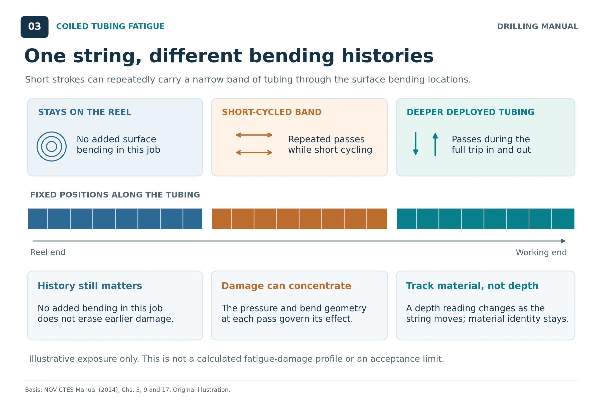
A depth reading tracks deployment; it does not permanently identify a piece of tubing. During movement, different material sections pass the reel and guide arch. A fatigue-tracking system must therefore relate measured depth to each section’s position along the string [1, 2].
Consider an operation that reaches a target depth and then makes repeated short strokes. The deeper tubing may remain in the well throughout those strokes. Meanwhile, a narrower band repeatedly crosses the surface bending locations. That band can accumulate substantially more bending exposure than neighboring sections [1, 2].
This is particularly relevant to coiled tubing sand cleanout. Dowell specifically connects localized cleanout cycling with fatigue at the reel and gooseneck. Pressure during those repeated movements adds to the concern [3].
Therefore, total running footage is a coarse activity record. It cannot show where repeated bending occurred or what pressure accompanied each event. Also, a section that stays on the reel during one job may already carry damage from earlier work. Its prior history remains relevant [1, 2].
Tracking Coiled Tubing Fatigue During a Job
Required Records
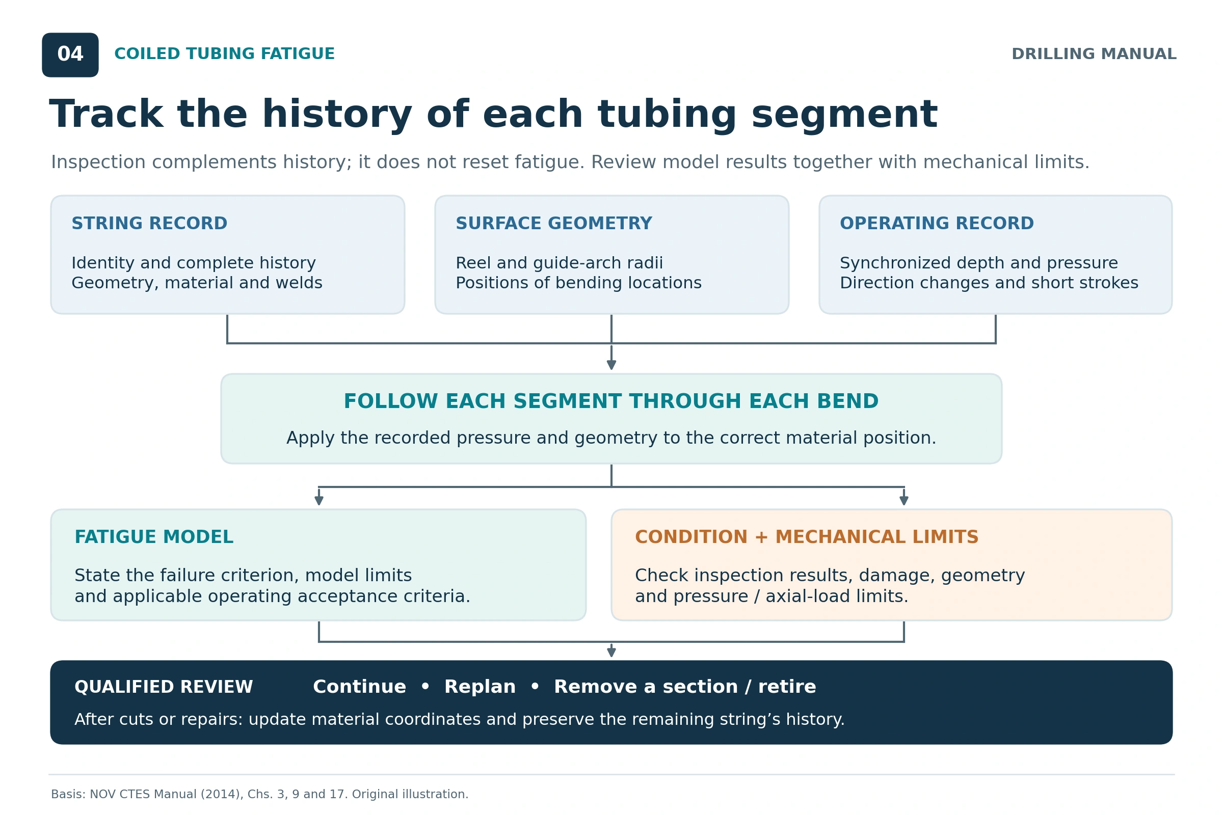
A usable coiled tubing fatigue assessment starts with an identifiable string and a reliable history. Specifically, the references call for geometry, material, movement and pressure data, together with records of damage and string changes [1, 2].
| Record group | Information to retain | Why it matters |
|---|---|---|
| String identity and position | Reel/string identification, length and material-position reference | Connects new events to the correct tubing section |
| Geometry and material | Outside diameter, wall profile, grade and applicable material data | Defines the local mechanical response |
| Surface arrangement | Reel geometry, tubing layer and guide-arch geometry | Establishes the bends encountered by each section |
| Operating history | Time-related depth, direction and internal-pressure records | Reconstructs bending events and their pressure conditions |
| Condition and exposure | Inspection results, mechanical damage, corrosion and relevant service loads | Identifies issues beyond an idealized fatigue calculation |
| String modifications | Removed lengths, splices, weld types and updated locations | Keeps the retained material’s history correctly mapped |
As a result, a repaired or shortened string needs an updated position map. The history of its retained tubing remains attached to that material. Simply starting a new length counter would lose the connection between the tubing and its previous service [1, 2].
Model Output and Failure Criterion
Tracking software divides the string into sections and applies the model as each section encounters a bending event. In addition, its output can show the estimated damage distribution and the effect of a proposed job. However, finer sections improve spatial detail without eliminating uncertainty in the material data or loading history [1, 2].
Before comparing percentages, establish what the model calls failure. Crack initiation and the first pressure leak are different criteria. NOV CTES explicitly distinguishes them in its example predictions. Therefore, percentages from unlike criteria or models cannot be treated as interchangeable measurements [1].
Also, avoid assigning an equal percentage of damage to every trip. SPE describes loading-sequence effects that can make equivalent later events more damaging than earlier ones. Therefore, simple trip counting cannot reproduce that behavior [2].
The engineering review combines this history with inspection and the relevant mechanical limits. For example, tubing deformation can affect passage through the injector head and stripper even before a modeled fatigue limit is reached [1, 2].
Applications of Fatigue Analysis
Coiled tubing fatigue analysis supports decisions before, during and after a job. Its main value is connecting the planned operation with the condition and history of the specific string [1, 2].
| Application | Question the assessment helps answer |
|---|---|
| String selection | Can this string accommodate the anticipated loading and bending history? |
| Equipment comparison | How do different reel and guide-arch arrangements change imposed deformation? |
| Cleanout or milling planning | Which material sections will experience repeated short strokes? |
| Real-time review | Does actual movement and pressure differ materially from the planned history? |
| Post-job management | Which sections need further assessment before the next operation? |
For coiled tubing drilling, repeated reaming or work across a narrow depth interval can concentrate exposure. The same tracking principle applies to other repeated interventions. However, the next job’s predicted demand must be evaluated against the existing local history [1, 2].
Reducing Coiled Tubing Fatigue in Practice
The sources identify several ways to reduce fatigue demand: larger bending radii, appropriate tubing dimensions, lower pressure during bending and fewer unnecessary local cycles. Nevertheless, these measures must remain compatible with the complete operation [1, 3].
For example, pressure reduction may favor fatigue life while conflicting with the flow needed for an effective cleanout. Any change must still meet transport, pressure-control and equipment requirements. Fatigue optimization therefore belongs within the overall job design [1, 3].
Likewise, changing stroke strategy can shift which material sections encounter the surface bends. The revised movement must be modeled and recorded; moving the exposure elsewhere does not erase existing damage. Removing or repositioning a section also requires correct coordinates and a review of the resulting string [1, 2].
Equipment condition matters as well. Worn or poorly fitting handling components can damage the tube. Consequently, maintaining the surface system and inspecting the tubing remain necessary even when a fatigue model predicts sufficient remaining capacity [1].
Rules of Thumb for Coiled Tubing Fatigue
The following rules summarize the book principles as screening guidance. They are not numerical acceptance limits or substitutes for a string-specific assessment [1–3].
- Count events using the system’s definition. Six bending or straightening events make one full trip in the conventional arrangement.
- Track the section, not only the footage. Short strokes can repeatedly load a narrow material interval.
- Keep pressure beside the movement record. The pressure during each bend affects damage.
- Increase radius with the full arrangement in view. Larger curvature radii reduce geometric strain at the same tube diameter.
- Treat geometry as one part of the assessment. Pressure, wall thickness, grade, condition and history still matter.
- Preserve the history after modifications. Update lengths and weld locations without resetting the retained material’s record.
- Read the model’s failure definition. A predicted crack-initiation fraction differs from a pressure-leak criterion.
- Use inspection alongside fatigue tracking. A satisfactory inspection does not provide a universal number of remaining trips.
Limitations of Coiled Tubing Fatigue Predictions
Geometry alone does not predict life. The Do/(2R) calculation omits pressure interaction, cyclic material behavior and accumulated history. Therefore, it explains deformation without producing an allowable trip count [1, 2].
Predictions depend on their inputs. Missing pressure or movement records leave the event history incomplete. Incorrect dimensions, material parameters or string coordinates can then assign the wrong response to a section. More decimal places do not repair those gaps [1, 2].
Fatigue test results show scatter. Consequently, a modeled life is an engineering estimate tied to its calibration and acceptance basis. An example curve for new tubing cannot establish the remaining life of a used string [1, 2].
Model coverage must be checked. Corrosion, mechanical damage, welds and dimensional change may need additional treatment. For example, the older references describe limitations of the models available at publication. For a selected system, verify its actual scope rather than assuming that every mechanism is included [1, 2].
A fatigue percentage is not complete approval for service. Pressure containment, tension, collapse resistance, tubing dimensions and equipment compatibility remain separate considerations. Assess them together with the pressure-control arrangement and the planned operation [1, 2].
No universal retirement percentage follows from these references. For example, NOV CTES describes an 80% decision point chosen for one illustrated operation. It explicitly identifies that value as an arbitrary service-company choice. It must not become a general rule for every string or model [1].
Questions to Resolve Before Reusing a String
Before accepting another operation, review the current condition, documented history and proposed loading together. Accordingly, the following questions turn the source principles into a practical engineering review [1, 2].
- Does the record identify the actual string, its length and the positions of retained material?
- Are previous pressure and movement histories complete enough for the selected model?
- Do the model inputs match the tubing dimensions, material and surface geometry?
- Which sections will repeatedly cross the reel or guide arch during the proposed job?
- Have inspection findings, welds, corrosion and mechanical damage been addressed?
- What failure criterion and acceptance basis apply to the predicted fatigue profile?
- Have cuts, repairs and other changes been incorporated into the position map?
These questions complement the equipment and operating review. They do not authorize a job from the strain example or from one reported percentage.
Frequently Asked Questions
How Many Trips Can a CT String Make?
There is no single answer that follows from tube diameter alone. Pressure, bend radii, wall thickness, material, prior exposure and condition all contribute. In addition, different sections of one string can accumulate different histories. Therefore, use the relevant model and acceptance basis for that string [1, 2].
Can Inspection Prove the Remaining Fatigue Life?
Inspection provides information about condition and detectable damage. However, a satisfactory result does not reconstruct the full pressure-and-bending history or establish a remaining trip allowance. Therefore, the sources support using inspection and fatigue records together when assessing further service [1, 2].
Does Thicker Tubing Always Solve the Problem?
Thicker walls improved life in the source fatigue comparisons under their stated conditions. Nevertheless, thickness alone does not account for pressure, radius, material, defects or the work already performed. The entire string and operation still require evaluation [1, 3].
Does Cutting Tubing Reset Its Fatigue History?
No. Removing material changes the string’s length and may change which sections encounter later bending events. It does not reverse the loading already experienced by the retained sections. Therefore, update their position references while preserving their previous histories [1, 2].
References
[1] NOV CTES. Coiled Tubing Manual, revised 27 June 2014. Chapter 3, pp. 3-11–3-15, including Equation 3.1; Chapter 9, pp. 9-2–9-24; Chapter 17, pp. 17-45–17-51. NOV CTES manual request.
[2] Mitchell, Robert F., editor. Petroleum Engineering Handbook, Volume II: Drilling Engineering. Society of Petroleum Engineers, 2006. Chapter 16, “Coiled-Tubing Well Intervention and Drilling Operations,” principally pp. II-708–II-722, with monitoring discussion on p. II-702.
[3] Schlumberger Dowell. Coiled Tubing Client School Manual. Section 3, pp. 14–19; Section 4, p. 4; and Section 5, p. 14. Publication date is not established in the reviewed copy.