Coiled Tubing Drilling (CTD) has evolved rapidly since its first operations in 1992. The main motivation for drilling with coiled tubing was the presence of large diameter CT which makes it easy to deliver the required hydraulic horsepower to the downhole. This horsepower is mandatory for hole cleaning, transferring cuttings in the annulus, and providing power to downhole mud motors. In addition, utilizing heavier and more sustainable tubings helped in providing the necessary weight for drilling & withstand torque (Torque and Drag in Drilling) resulting from drilling operations.
Drilling With Coiled Tubing Applications
There are several methods by which CTD applications have been categorized. Most operations can be described using the following criteria (Fig. 1):
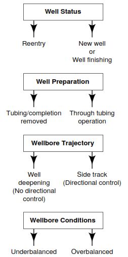
- Well status – new or re-entry well
- Wellbore trajectory – Sidetracking Drilling or deepening
- Well preparation – Retrieving tubing/completion or thru-tubing
- Wellbore conditions – overbalanced or underbalanced drilling
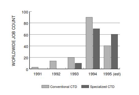
From 1991 to 1994 (the below figure shows the global trend of utilizing CTD), there were two main categories of CTD operations:
- Operations that use the assistance of conventional drilling equipment and techniques.
- Operations that utilize the unique capability of CT
Nowadays, the increasing demand for CTD is previously expected as there are improvements in its techniques and reliabilities.
Advantages Of Utilizing Coiled Tubing In Drilling
The factors, or advantages, associated with CTD that have provided the impetus for the service development can be categorized as shown below:
- Safety & Environmental
- Technical
- Financial
Safety & Environment
The configuration of the coiled tubing well control equipment provides a higher level of controlling well kicks than in the conventional drilling with drill pipes. This level of control is due to the lower proportion of pipe tripping, handling, and tool joints making & breaking. Also due to the fully contained well pressures that are provided by CT well control equipment, the risk of taking a kick (causes of kicks in drilling) is not as much of a threat to manpower and equipment as in conventional drilling operations.
Also by minimizing the well site area, we managed to reduce the drilling noise impact. The simplicity of equipment compared to conventional drilling also plays another role. In addition, operations using continuous tubing rotated on CT reel cause significantly less noise pollution than those using connecting drill pipe
Financial
The significant objective of early CTD attempts is to reduce costs. The major items that CTD depends on to save costs are:
- The reduced hole size (slim hole)
- The reduced well site area
- Lower mobilization costs
From a Technical Point Of View
- Underbalanced Drilling: CTD is more than perfect in underbalanced drilling. If we think a little bit, we would find that the main cause is its safety advantage (better well control). Also, Underbalanced drilling is being used to decrease reservoir damage (as it reduces the fluids invasion in the formation) that will typically be achieved by using CT through the production tubing.
- Sidetracking & Deepening: CTD offers noteworthy operational and cost advantages compared with conventional drilling, especially in depleted zones. Eventually, it is intended that the techniques and equipment used in CTD will provide a level of control and response that will permit “joystick drilling”
- As we can use the wireline thru coiled tubing even while tripping, it will give us a chance to have more realistic data than that transferred by mud pulses.
- The ease of equipment mobility.
- Lower trip times (no need for connecting or disconnecting the coiled tubing)
Limitations and Disadvantages of Coiled Tubing Drilling
The limitations and disadvantages of CTD are as follows:
- From a financial point of view:
- in many areas, the abundance of low-cost conventional rigs renders the use of CTD for some applications uneconomic. In such areas, only specialized CTD techniques which cannot be completed by conventional equipment will be viable.
- The cost per foot of CT is more expensive than that of OCTG. in addition, there will be a need to junk the used tubing of CT after 6 or more trips depending on the drilling operations. On the contrary, the drill pipes have a longer life than such tubings.
- From a technical point of view:
- The advantage of being able to drill slimhole is, in some applications, countered by the inability to use a higher pump rate, WOB, or torque. And also, there will be a limitation in drilling larger hole sizes.
- currently, CTD can’t be used in drilling the reach and horizontal sections of horizontal and high-angle holes.
- Since the CT drill string cannot be rotated, it is mandatory to use downhole tools (such as RSS drilling)
- The tubing life is difficult to be predicted and a pipe failure can suddenly occur.
- Limited drilling-fluids life: In CTD, it is not recommended toincrease solids in mud as it may cause erosion of string
- Due to the limited spread of such technology except in certain areas, there will be a limited experience and equipment.
- In overbalance drilling, differential pressure can increase the chance of differential sticking of bottom hole assembly. This also can happen while drilling with coiled tubing as CT is run while there are residual stresses in CT that will cause a being buckled while RIH.
CTD Design
To fully design and CTD operations, you will have to go thru following steps:
- Establish the objectives
- Review the technical feasibility
- Technical preparation
- Administrative preparation
Determine The Objective
The first aim of drilling a well is to reduce its cost as much as possible. So the following question shall be on table while preparing for Coiled Tubing Drilling operations.
- What is the objective of drilling the well?
- Production
- exploration
- delineation
- delineation
- What is the purpose of CTD operations instead of conventional?
- Why do we need to drill it underbalanced or overbalanced?
- In addition, the techniques and criteria by which we can meet our goal, should also be clear.
The majority of CTD requested may be included in these varieties:
- New development wells
- Existing well sidetracking
- New exploration wells
- Existing well deepening
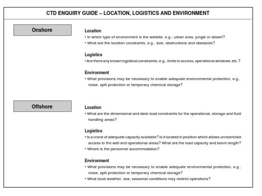
The location and logistic concerns outlined in Fig. 3 apply to all CTD applications. To assist with the data acquisition process, an inquiry guide for each application is included in Fig. 4 through Fig. 6. A summary of the current technical capabilities is also included.
CTD Enquiry Guide – New Wells & Vertical Well Deepening
| Exploration and production objectives | Is this an oil or gas well? Data collection 1- Logging program. 2- Mud logging requirements. 3- Production casing or casing liner sketches. |
| Wellbore design | Wellbore geometry 1- TD and open-hole sizes? 2- casing program, i.e., casing size and float shoe depths. Deviation 1- Projected well profile, i.e, inclination, and azimuth versus depth. 2- Acceptable target tolerance from the designed well trajectory (check well trajectory calculations). 3- The maximum acceptable deviation in case the well is vertical. Downhole conditions 1- Well lithology. 2- The formation pressures and temperature. 3- The presence of sloughing shales. 4- Risk if there are shallow gases. 5- Likelihood of H2S. |
| Operations | Bit and drilling performance 1- The available information about the formation(s) drillability. 2- Offset well bit records. Drilling fluid 1- Is the reservoir to be drilled under or overbalanced? 2- The Types of Drilling Fluids that will be used (Oil Base Mud – Water Based Mud – Air Mud). 3- The drilling fluids’ properties. 4- The probability of lost circulation Problems & the use of LCM in drilling |
Coiled Tubing Drilling Enquiry Guide – Existing Well Sidetrack Reentry
| Production and completion objectives | Production oil, gas, or injection well. Completion 1- The Casing liner size. 2- The minimum acceptable liner size 3- Liner cementing operations are planned or without cement 4- The configuration of new completion |
| Wellbore design | Wellbore geometry 1- The TD and open-hole sizes 2- Casing Sketch Deviation 1- The existing well profile, i.e, inclination, and azimuth versus depth 2- The kick-off technique will be used. 3- The re-entry well profile, i.e., kick-off depth, build up rate, inclination, azimuth, and drain hole length 4- The acceptable target tolerance from the directional plan Downhole conditions 1- The formation pressures and temperature. 2- The well lithology. 3- Are there any sloughing shales? 4- The likelihood of H2S |
| Operations | Bit and drilling performance 1- The formation(s) drillability. 2- Are offset well bit records available? Drilling fluid 1- What type of drilling fluid(s) is to be used, i.e., mud, foam, or air? 2- Is the reservoir to be drilled under or overbalanced? 3- What is the likelihood of lost circulation or losses? 4- What are the properties of the mud system to be used, i.e., type, density, and characteristics? |
Technical Feasibility
When assessing the technical feasibility of any CTD operation a logical and methodical approach is essential (Fig. 7). The following areas should be investigated and the relevant criteria determined (depending on the specific application and conditions).
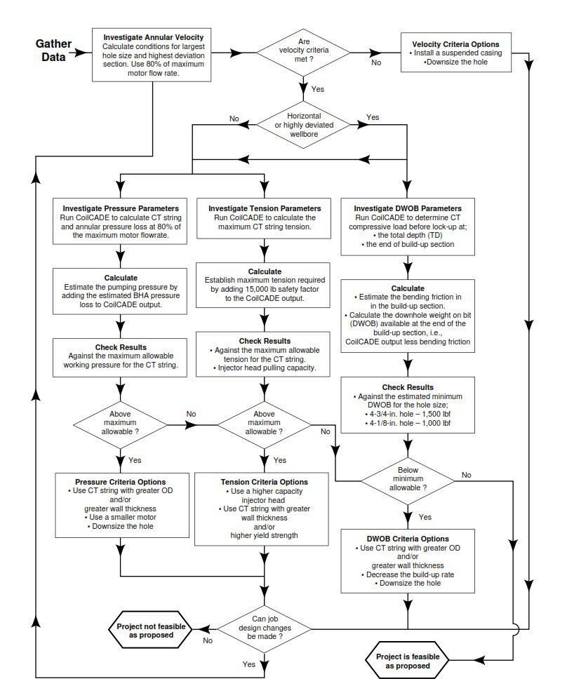
A summary of the constraints which may limit the application or extent of Coiled Tubing Drilling operations is shown in below tables:
- Weight on bit
- Annular velocity
- Pumping pressure and rate
- CT string tension
- CT life/fatigue
- Torque
- CT reel handling
- Directional requirements
Limiting Parameters Related To Drilling Rate ROP
| Constraints | Limitation | Equipment Limitations | Design Limit | Remarks |
| Hydraulic power at the bit | Maximum flow rate | • CT length and diameter • Mud type, weight, yield • CT Max allowable pressure • Motor maximum flow rate | • Hole diameter • Hole depth | Use the largest fishable motor for the hole size for maximum flow rate (consider max allowable CT pressure). Use CT string length appropriate to the well TD. Use a shear-thinning mud to minimize the pressure loss. |
| Mechanical power at the bit | Torque | • CT max allowable torque • Motor max torque | • Hole diameter | Use a motor with the maximum torque in its category. Ensure the CT and BHA max allowable torque is less than twice the motor stall torque. |
| RPM | • Motor speed • Bit max operating speed | • Hole diameter | Two basic types of slim hole motors are available: high speed/low torque or low speed/high torque. A drill off test is necessary to optimize ROP and minimize drill string vibrations for a given formation and motor/ bit combination. | |
| Weight on Bit (WOB) | • BHA ID, OD, and length • CT diameter, wall thickness and yield | • Build-up rate • Drain hole length • Hole diameter | in the case of vertical or slightly deviated holes, drill collars are used to provide WOB, but for highly deviated or horizontal wells, the CT provides the WOB and the maximum compressive load at the CT end before lock-up, is the limiting factor. “The maximum available compressive load at the end of the CT must be estimated using coilCADE in two critical positions: in the build-up section and at the total depth (TD). • In the build-up section, the max CT compressive load before lock-up must be sufficient to overcome the bending friction force of the BHA (not taken into account by coilCADE) while providing sufficient WOB to drill at an acceptable rate. • At TD in the horizontal or deviated section, the max CT compressive load before lock-up given by coilCADE is the maximum available WOB at TD. |
Limiting Parameters Related To Tripping And Hole Cleaning
| Constraints | Limitation | Equipment Limitations | Design Limit | Remarks |
| Pull capacity | Tension | • CT max allowable tension • CT Injector Pulling capability • BHA max allowable tension | •Hole depth | The maximum tension must at least be equal to the maximum hanging CT and BHA weight + the estimated maximum hole drag (CoilCADE) + a recommended safety margin for overpull (15,000 to 20,000 lbf). |
| Hole cleaning | Minimum annular velocity | • CT Max allowable pressure • CT length and diameter • Motor maximum flow rate | •Hole diameter | As a general rule, the minimum velocity in a vertical wellbore section is 40ft/min. In highly deviated wellbores 100 ft/min should be used as a guide. The Wellbore Simulator should be used in the assessment of critical cases. The annular velocity should be considered in the largest hole section which is generally the upper hole section where the casing is the largest and in the most deviated hole section. |
Coiled Tubing Drilling Project Preparation
The necessary tasks to be completed in this level of CTD project preparation may be summarized as technical or administrative. Regardless of how the various elements are categorized, each should be regarded as a key component that is essential for the completion of a safe and successful CTD project.
Technical Preparation
Technical preparation includes a lot of tasks that should have a timeline. These preparations shall be according to a checklist that includes the following:
- Basic equipment and services
- Surface equipment
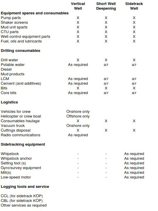
- Consumables
- Spare parts and supplies
- Downhole tools
- Associated services
- Procedures and planning
- Mob/demob organisation
- Rigging up/down
- Setting whipstock & milling window (if required)
- Well control
- Well control equipment testing
- Bottom Hole Assembly deployment even overbalances
- Running and setting liner or casing running (if required)
- Running completion string
- Cementing Design program
- Mud program
- Contingency plans
- Emergency responses (in the event of a fire, etc)
- Drawings and schematic diagrams
- Wellbore schematic (at each stage of the operation)
- Well Trajectory plot if deviated
- Surface equipment layout with dimensions (or scale) including an indication of restrictive zoning where applicable, e.g., Zone II
- BOP stack schematic with heights and dimensions
- BHA schematics (fishing diagram for each assembly)
- High pressure and low-pressure lines schematics
- Electrical wiring of surface equipment
- Personnel
- Training and certification of personnel
- Personnel job descriptions
- Operations and support organization organograms
To enable the efficient management and coordination of these individual areas, it is advisable to prepare a list of tasks required to complete technical preparation. Such a list should contain data on the task, appointed person, timeline to finish, and additional data appropriate to the specific task.
Administrative Preparation
The final agreement or contract between the company and the operator should include the following sections:
- Crew list provided by the contractor
- Equipment list that both oil and gas company and contractor obligated to provide
- Services List that both company and contractor obligated to provide
- Day rates, lump sums, incentives, penalties including force majeure, and Liability clauses as any other service contract.
Coiled Tubing Drilling CTD Equipment
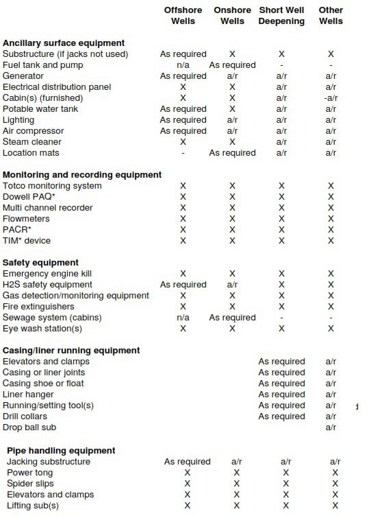
The sort of application, location, and complexity of the planned well will determine which items of surface equipment are specified and then selected. The principal items required to complete most coiled tubing drilling operations can be classified as follows.
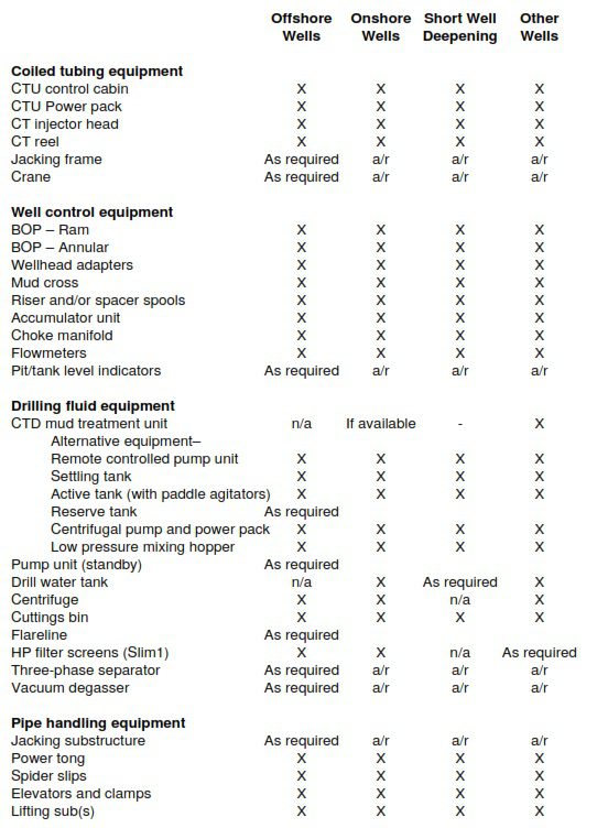
- CTD substructure or rig
- Well control equipment
- Pumping equipment
- Rig camp and wellsite facilities
- Pipe handling equipment
- Ancillary surface equipment
- CT equipment
- Monitoring and recording equipment
- Mud storage and treatment equipment
- Safety and emergency equipment
Rigs and Structures for CTD
Coiled tubing drilling is completed with the support of conventional rotary rig masts and substructures, and with specially manufactured substructures and jacking techniques developed for CTD. For obvious reasons, substructures designed specifically for CTD offer the greatest potential for its application.
Well Pressure Control Equipment
- 4-1/16-in. 10,000 psi quad-ram BOP– standard for CTD operations (Fig. 18).
- Blow out Preventer size and pressure rating – the blowout preventer size or bore relies on the hole or planned completion string size. Two BOP sizes widely used are 4-1/16-in. and 7-1/16- in. In some circumstances 11-in. BOPs are used. For most CTD applications, a 5,000 psi pressure rating is acceptable but the operating pressure rating must exceed the expected bottom hole pressure.
- Annular BOP/CT stripper – for CTD, the only function of this BOP is to close on the BHA when tripping the BHA or on the casing liner (check also Liner Hanger System) if a double ram BOP is to be used. Alternatively, it is okay to drop the BHA in the hole in case of a kick while tripping the BHA. However, local regulatory agencies generally ask for one annular BOP. Annular BOPs are available in 4 -1/16 and 7-1/16-in. sizes.
- 7-1/16-in. ram BOP – found in single or double, shear/ seal or ram configurations. The shear rams can shear the 3-in OD BHA components.
- Choke line – used to divert the flow to the choke manifold while controlling a kick and choking wellbore returns.
- Kill line – used to kill the well by pumping through/ down the annulus (wait and weight method Driller’s method).
- Choke manifold – as in the well control normal procedures, its pressure rating must be consistent with the BOP rating. The manifold must be a drilling type choke manifold with two manual chokes and one pressure gauge (some applications may require a remote-operated choke). This equipment is as important as the BOP for the rig safety (Fig 17).
- BOP controls and instruments – the stripper and BOP are controlled from the CT unit control cabin. For the 7-1/16-in. BOPs and the remote-operated valves on the mud return or choke lines, the control position is found on the BOP accumulator or Koomey unit that must be positioned next to the CTU cabin. Remote controls between the accumulator and the CTU BOP command panel can be adapted if necessary.
- Mud return line – normally not part of the well control equipment but when using two BOP stacks, the mud return must be closed if it is necessary to shut in the well. This is achieved with a remote operated valve installed on the outlet of the mud return mud cross.
Coiled Tubing Drilling Equipment Package
- Injector Head – for new and deviated wells, a minimum of 60,000 lbf pull capability is advised. For well deepening a 40,000 lbf capacity injector head may be utilized if applicable. A 72-in. radius gooseneck is required for 1-3/4-in. and larger CT.
- Power pack for CT– If nonstandard equipment (e.g., high capacity injector head) or auxiliary equipment is to be powered by the CTU powerpack, confirmation should be made that the output of the power pack is adequate and that the pressures and flow rates are compatible.
- Coiled Tubing – for new and deviated wells, CT sizes of 1-3/4, 2, or 2-3/8 inch. are required. A wall thickness of at least 0.156-in. fabricated from 70,000 or 80,000 psi yield strength material is advised. For drilling sidetracks, determine the optimum size, wall thickness, and yield strength through simulation software. For simple well deepenings 1-1/2-in. CT can be used in certain cases.
- The Drum (CT Reel) – the reel capacity (string length) and weight should be confirmed. Also, a reel core expander may be required for 1-3/4-in. and larger CT and the CTL reel will be equipped with a normal reel collector and pressure bulkhead equipment.
- The Crane – for onshore operations, an independent crane truck is preferred to an integrated crane CTU trailer. Boom length must be sufficient to handle a 40 ft pipe/BHA over the substructure.
- Wireline (for directional drilling with wireline) –A mono cable is needed for the Baker Inteq or ENSCO or Drilex steering tool operation. A Hepta cable is required for the Anadrill Cobra wire line BHA.
Kick Detection Equipment
When drilling overbalanced (check underbalanced drilling), rapid detection of kicks or mud losses is essential in slim hole drilling applications. There are two common methods used in kick detection systems. Both have pros and cons when used in CTD operations.
- Mud tank level monitoring
- Flow comparison (flow in vs. flow out)
Mud System
Mud Tanks
There are three types, or functions, of mud pits, i.e., settling, active, and reserve. Additional tankage or storage facilities may be required for water (Fig 19).
Active tank
The active, or suction, pit stores the drilling mud and supplies the mud pump suction. If continuous treatment or additive is required it may be added to this tank. The tank volume is generally around 50 BBL for 2 to 3 bbl/mn flow rates. This allows a mud volume buffer to help stabilize the mud properties & characteristics. Smaller volume active tanks may be used, however, key fluid parameters such as viscosity and density can vary quickly if the mud volume is small. The active tank suction is manifolded to allow recirculation and precharging of the high-pressure pump. In addition to the recirculation line, a tank agitator is required to maintain the homogeneity of the fluid.
Settling tank
In general, This is the first pit through which the wellbore returns the pass and the shale shakers (where fitted) will normally be located above this tank. An overflow system from the settling pit passes to the active tank. Generally, the settling tank volume is typically 10 to 15 BBL for 2 to 3 bbl/mn flow rates. A large (butterfly) valve is generally fitted to the base of the tank to allow easy removal of the accumulated solids.
Reserve tank
The reserve tank(s) are used to store a reserve of drilling mud and also provide a facility for mud remedy or preparation. Ideally, the reserve mud volume should be equal to the hole volume plus the active and settling tank volumes. However, this may be reduced if the well type (exploration or development), downhole pressure, or risk of circulation lost problems. Approximately half to one-third of this volume can be furnished in the re-entry of the depleted reservoirs. Similar to the active tank, the reserve tank should be equipped with a recirculation and agitation system to allow conditioning of the mud.
Нормально пишете все