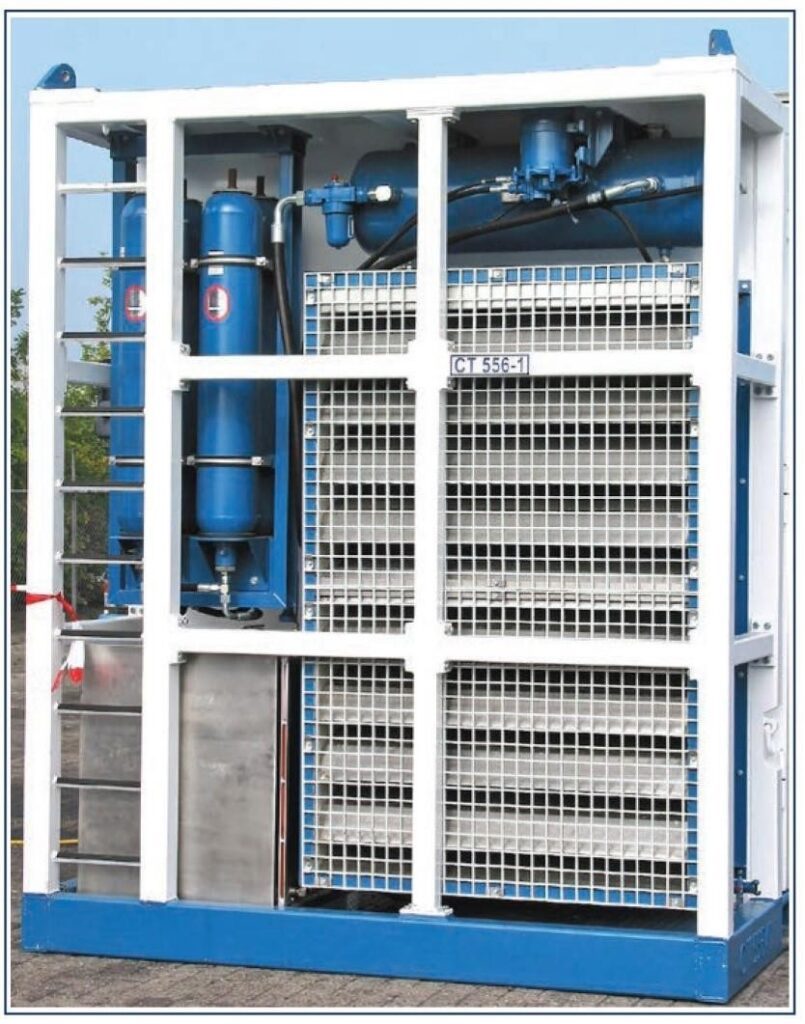
The Power Pack or Power Unit supplies hydraulic power to the coiled tubing equipment unit. Most conventional units use a diesel engine (examples are Scania DN14 and Detroit 8V71 engines) to power hydraulic pumps, which in turn drive the hydraulic motors in the injector head, tubing reel, and well control systems. The engine is independent of rig power and air systems. As an alternative, electric motors may be used to drive the hydraulic power pack.
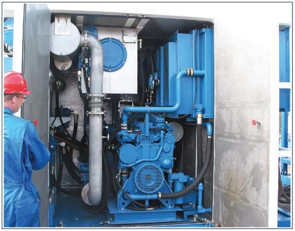
Mounted in the Power Pack are two nitrogen-charged hydraulic accumulators, which provide essential backup energy for the well control and auxiliary equipment, should the unit fail, or have to be stopped for any reason. The BOP accumulators are a standard bladder type and should retain the pre-charged nitrogen pressure even in extreme circumstances.
Diesel engines fitted to coiled tubing reel units must be fitted with the following safety devices to comply with hazardous zone 2 (Oil Rig Hazards) requirements (5m or16 ft from wellhead):
- Anti-static fan belts
- Exhaust spark arrester
- Explosion proof instrumentation
- Emergency shut down device
- Air or hydraulic starter
Engines will shut down automatically under conditions of High Temperature, Low Engine Coolant, Low Oil Pressure, etc. These conditions are monitored by actuators which sense either pressure loss or temperature increases. The actuators are linked, via trip indicators on the control panel, to the engine shut fuel shut off, and the engine air intake. The whole system is charged with low-pressure air, and this 4.1 bar (60 psi) of air pressure must be maintained to keep the system from tripping. If the actuators operate they vent the air pressure, and hence trip the system.
Coiled Tubing Power Pack Systems:
There are six systems typically supplied from the coiled tubing Power Packs:
- Main Injector Circuit – two hydraulic pumps at 227 LPM (60 GPM) and 113.5 LPM (30 GPM). Supplies to Injector Head motors at 207 bar (3000 psi).
- Reel Circuit – hydraulic power to reel motor only, variable to a maximum of 138 bar/60.5 LPM (2000 psi/16 GPM).
- Levelwind Circuit – the level wind is the leadscrew assembly that spools the tubing onto the drum, variable to 172 bar/113.5 LPM (2500 psi/30 GPM).
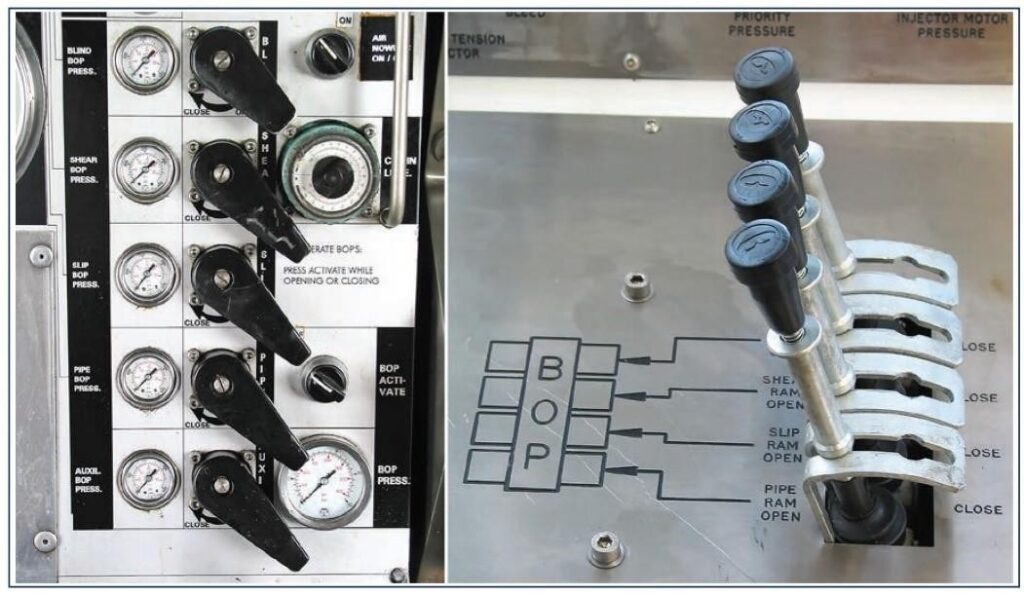
- BOP Circuit – The blowout preventer (BOP) is hydraulically operated by oil stored in a Nitrogen charged accumulator. A pressure-controlled activator maintains the charge in the accumulator, which when fully charged can typically operate the BOP through two complete cycles (max 207 bar/45.5 LPM or 3000psi/12 GPM). A hand pump is provided for emergency operations.
- Priority Circuit – supplies the various controls and ancillary features of the CT unit. Variable pressures up to 138 bar/45.5 LPM(2000 psi/12 GPM).
- Auxiliary Circuit – for additional pieces of equipment that require hydraulic supply. Preset up to 207 bar/106lpm (3000 psi/28 GPM).
Output pressure control valves are used to control the operation of the injector and reel, by imposing a given oil pressure on the hydraulic motors. This is converted directly into a maximum
attainable torque. Adjustable relief valves on the injector drive circuit can be set to limit pressure, restricting pull and thrust to a safe level. This is particularly important when operating small or medium coil sizes in large-size casings. In these instances, critical buckling loads may only be a few thousand pounds-force.
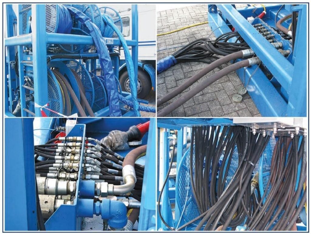
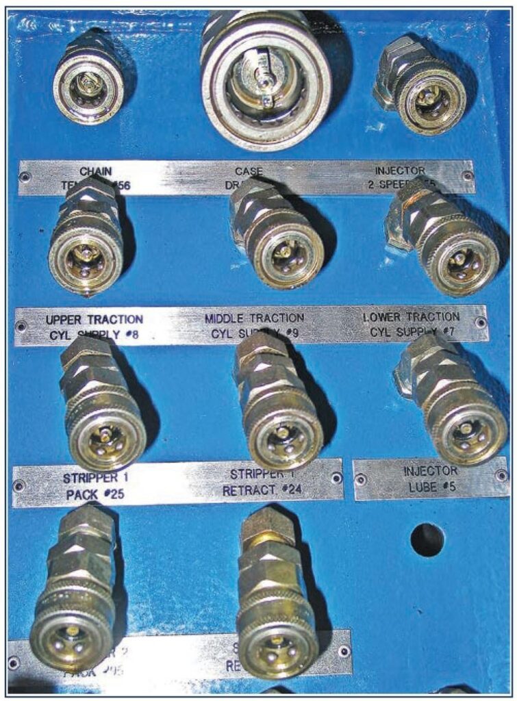
The hose connectors on the majority of CT units are a quick-connect type, known as a snaptite. The two main injector hoses are slightly different in that they are threaded and have to be screwed together. Both types of couplings have an integral poppet that prevents oil leakage when disconnected.
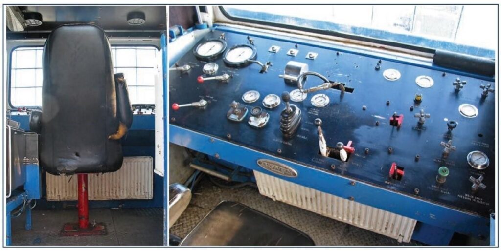
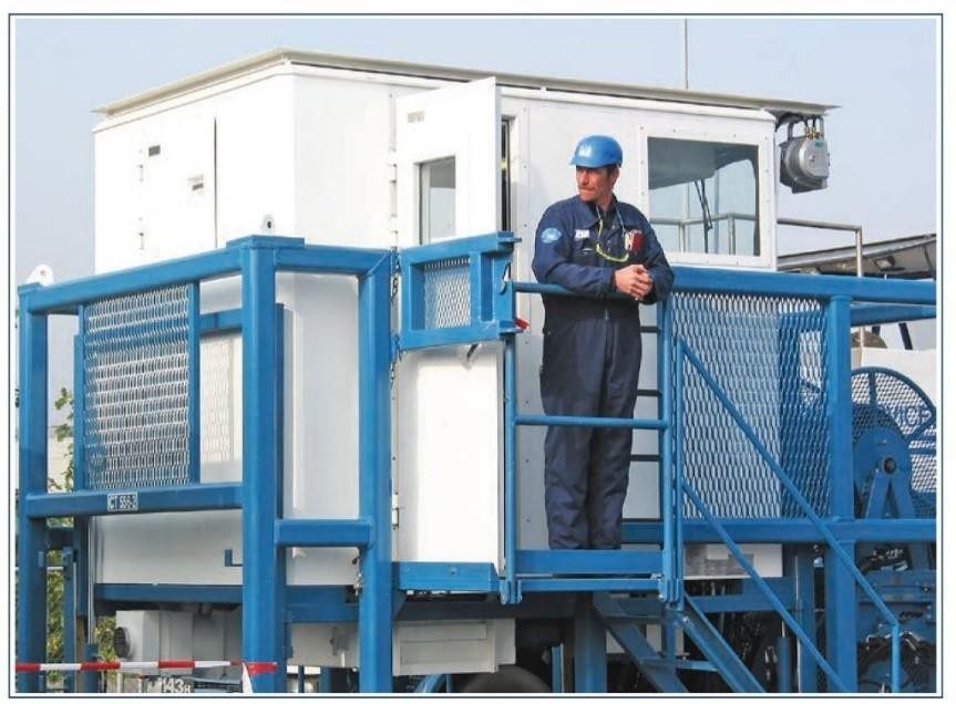
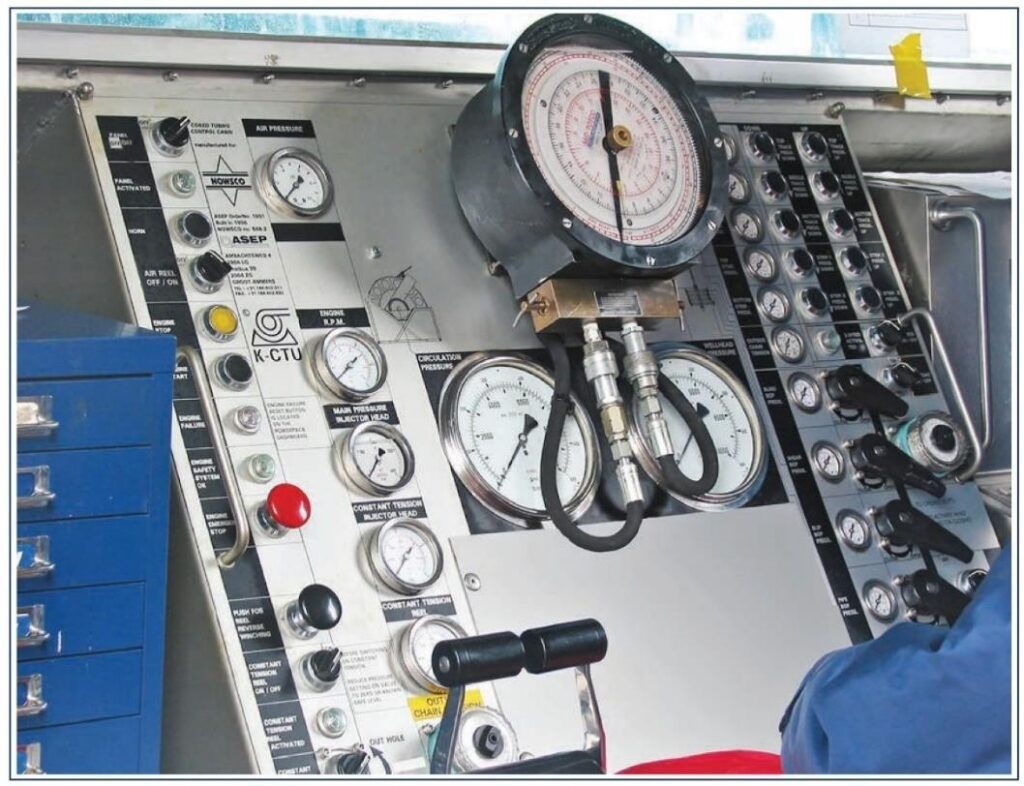
Control Cabin
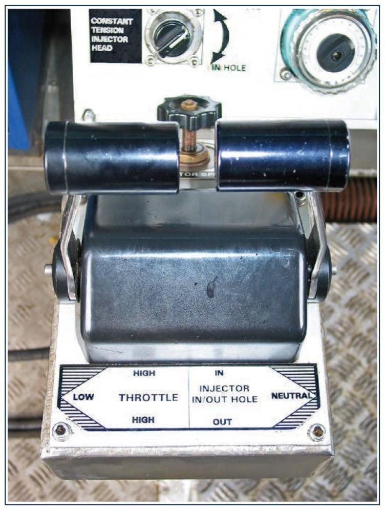
The control cabin is sited to provide a clear view of the wellhead, injector head, and the tubing reel. The CT operator controls all the equipment from within the Control Cabin using hydraulic pressure control valves.
The valves are predominantly remote pressure valves, i.e. solenoid actuators and to the main hydraulic control valves, the oil pressure and flow required. Relief valves on the main Injector Drive circuit, are set to a predetermined pressure to restrict the tubing “Pull Value”. This means that in the event of the tubing becoming stuck while pulling out of the hole, the applied torque will not exceed the tensile limit of the tubing. The Control Cabin houses all the controls relevant to the operation, which include:
All of the above systems are mounted within easy reach/view of the CT operator
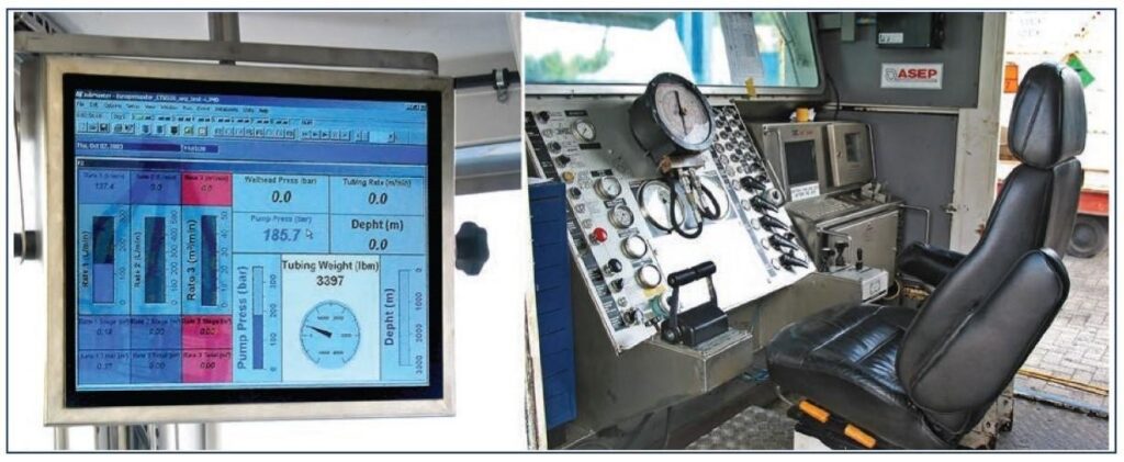
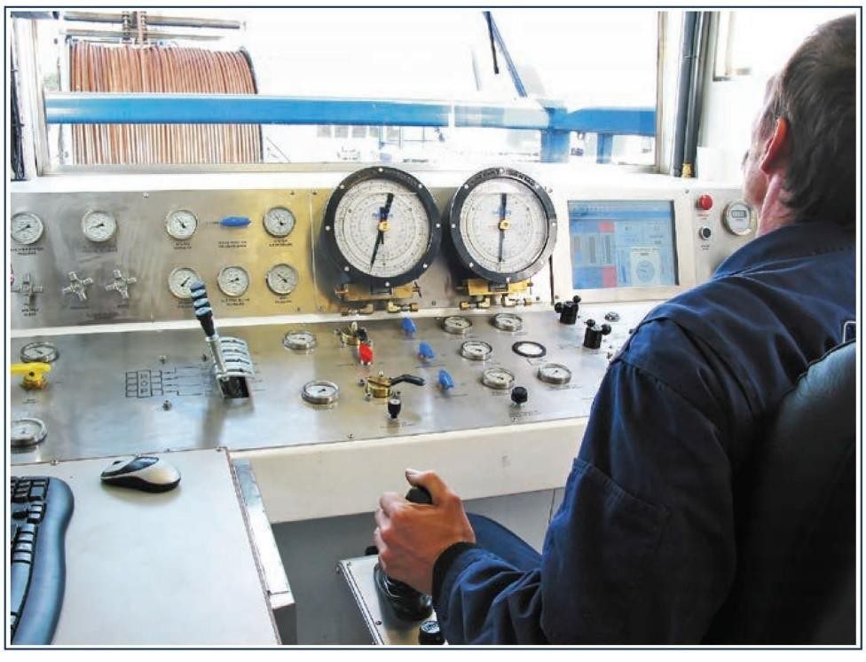
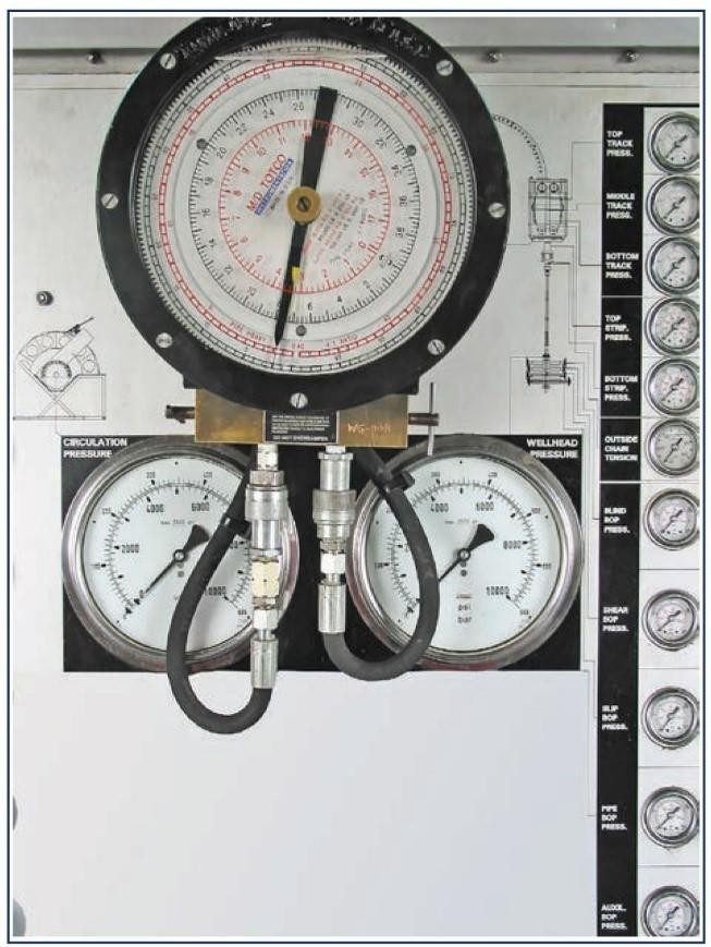
The main recording instrumentation generally includes:
- Hydraulic Pressure Gauges (injector traction cylinders, etc.)
- Tubing Depth Meter
- Tubing Load (Weight) Indicator
- Wellhead Pressure Gauge
- Coiled Tubing Power Pack Engine Temperature and Pressure Gauges
- Circulating (reel/pump) Pressure Gauge
- BOP Pressure Gauge
Control Cabins are becoming more complex with regard to electronic/digital displays and monitoring. There is quite a difference in 20 years between a basic Control Cabin (circa 1985) and a newer computerized control Cabin (circa 2005)!