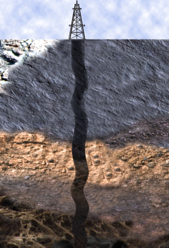
In oil and gas wells, hole deviation is a common drilling problem caused by a number of factors. This deviation results in the wellbore not being perpendicular to the target formation. Also, this can lead to a number of issues, including reduced productivity, lost circulation, and even well blowouts.
We can control hole deviation by a number of methods. Such as, proper bit selection, maintaining the correct weight on bit, and avoiding oil and gas doglegs. Additionally, proper well planning and execution are essential to keeping hole deviation under control.
In this article, we will discuss the causes of hole deviation and the methods that can be used to control it.
Mechanical Behaviour Of Drilling Assemblies
Mechanical Forces On The Bit
The principal mechanical forces which cause a drilling bit to deviate are called the “buckling” and “pendulum” effects. Figure 1 shows such mechanical forces.
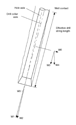
Forces Group # 1
W1, W2, and W3 are forces that occur when there is a displacement of drill collars center line from the hole axis. This is due to the bending of the assembly.
- W1 = the total weight-on-bit, acting along the axis of the drill collar.
- W2 = one component of W1 which acts along the hole’s axis.
- W3 = a component of W1, complementary and normal to W2, acting at right angles to the hole axis. This force acts laterally at the bit.
Forces Group # 2
The forces W4, W5, and W6 are due to gravity and the inclination of the hole. Also, they illustrate the pendulum effect (Also Check: BHA Types).
- W4 = the vertical downward force caused by gravity acting on the length of drill collars below the wall contact point.
- W5 = one component of the drill collar weight W4 which acts along the assembly axis. It also contributes to the total weight-on-bit, W1.
- W6 = a component of W4, complementary and standard to W5. It acts at right angles to the drill collar axis and back towards the vertical. Part of this force also has a lateral influence at the bit.
Drill Collars Bending Effect On Hole Deviation
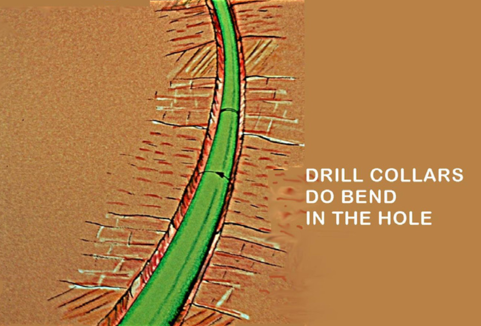
When applying weight to the bit, the drill collars lower part will bend to some extent under the compressive load. The direction of the force applied at the bit will then no longer coincide precisely with the hole center line. As the bit drills ahead, the lateral component of the bit weight, W3, will tend to deflect it.
The direction of W3 depends on the bending direction of the lowest part of the bottom hole assembly, which in turn depends on the geometry of the system – in particular, the position of the lowest two drilling stabilizers (which act as fulcrums). In figure 1, no stabilizer is present, the BHA is sagging towards the lower side of the hole, and the inclination at the lower end of the collars is greater than that of the hole. The inclination of the hole is thus likely to increase.
The amount of inclination change and the length of the assembly involved will depend on:
- The stiffness, i.e., the dimensions, of the drill collars.
- The hole diameter.
- The arrangement of stabilizers in the assembly.
- The compressive load applied
Bending Increase
Bending, and the corresponding directional force at the bit, W3, will increase by:
- Greater clearance between the drill collar assembly and the hole.
- Smaller, more flexible drill collars.
- More compressive force, i.e., weight-on-bit.
As bending increases, the length of the assembly mainly involved (from the bit to the first point of drill collar wall contact) tends to shorten. This is called the “active drill collar length”. In practice, the position of the first stabilizer determines this dimension. Usually, not more than the assembly’s bottom 50 m (150 ft.) is active in the absence of stabilizers or at a high inclination or with high bit weight, perhaps less than 20 m (60 ft.).
The Pendulum Effect Of Gravity On Wellbore Deviation
The effect of gravity on the drill collars below the wall contact point acts vertically downward. Part of this force is transmitted to the bit along the axis of the drill collars, and its complementary component, W6, acts towards the vertical, perpendicular to the axis of the assembly. This force is supported by the formation at the wall contact point and the bit (see Figure 1).
Considered separately, the influence of this lateral force at the bit reduces the inclination of the hole. Its magnitude increases:
- When the hole inclination is greater.
- When heavier drill collars are used below the contact point.
- When the active drill string length is increased.
In Figure 1, each of the above factors will tend to increase the value of the lateral component (W6) of the drill collar weight (W4) below the wall contact point.
Controlling Mechanical Factors & Hole Deviation
By changing the make-up of an assembly and altering the drilling parameters, it is possible to vary the magnitude of the lateral forces at the bits W3 and W6, which directly influence the tendency of the bit to deviate from the existing path of the hole in a vertical plane.
Note that W3 acts normal to the hole axis and W6 to that of the drill collars. For practical purposes, we can consider these forces to act in directly opposite directions.
Therefore, we can expect the inclination to increase if the effect of drill collar buckling is greater than the pendulum tendency, but it should decrease when the pendulum force predominates.
Formation Effects On Hole Deviation
Formation characteristics add considerably to the complexity of deviation problems. In addition, there are numerous theories to explain observed effects.
Formation Bit Interaction Or Abtisotropic Theory Of Rock Failure
In uniform rocks, equal chip volumes will form on each side of a bit tooth, and the bit drills straight ahead. However, in dipping laminated formations, larger chip volumes will form on one side of the tooth, pushing the bit laterally, with resultant wellbore deviation.
The magnitude of this effect varies with the degree of dip angle. Usually, the direction of deviation generated is up-dip for angles of dip up to 45° – 60° and down-dip for high angles of formation dip (over 60°).
There is no completely satisfactory explanation for naturally occurring deviation. However, theory and practice indicate that uncontrolled deviation will not exceed an angle perpendicular to, or parallel to, the formation dip.
Deviation Control In Vertical Hole
The overall objective in a vertical well is to achieve the most economical cost per unit length, consistent with keeping the inclination (among other essential factors) within acceptable limits.
This means selecting a drilling assembly that will produce an equilibrium of the deviating forces at the bit while allowing the maximum weight-on-bit and, therefore, the optimum drilling speed.
The two methods commonly employed to control inclination in vertical holes are:
- The pendulum technique.
- Packed-hole drilling assemblies.
More details about the above bottom hole assembly are in the rotary directional drilling BHA article.
The Pendulum Technique
Factors which determine the magnitude of the hole straightening force are:
- The drill collar’s weight below the wall contact point.
- The active drill string length.
- The weight-on-bit.
The use of heavier drill collars above the bit increases the lateral corrective force (W6). Larger collars are also stiffer and more resistant to buckling, and their larger outside diameter allows less displacement of the assembly from the centre line of the hole.
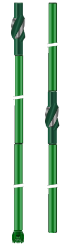
Raising the wall contact point by including a stabiliser at a specified distance above the bit increases the active drill string length, and also therefore the lateral force (W6). This will again reduce the displacement of the drill collars from the axis of the hole, and the deviating force (W3). This approach is limited by the possibility of buckling below the stabiliser if this is placed too high, which would then necessitate a reduction in bit weight.
Reducing bit weight alone will cause less buckling and encourage the correcting force (W6) to exceed the inclination building effect (W3), but less weight-on-bit will produce a lower rate of penetration and higher cost per meter.
Woods & Lubinski
In 1953/1955 Woods and Lubinski published data which recommended optimum stabiliser positions for the fastest penetration rate within given wellbore deviation limits. For quoted hole sizes and inclinations, combined with values for formation dip and an index which represents the severity of the formation effect, the tables specify:
- Drill collar diameter,
- Position of the first stabilizer above the bit,
- Allowable weight-on-bit,
all for a condition of zero hole deviation, i.e. equilibrium of the forces at the bit, and no increase in inclination.
Computer Programs
Modern developments of such research provide computer programs which evaluate a comprehensive range of forces acting at the bit and at other points in the assembly. In particular, we can predict the magnitude of the transverse forces exerted by the bit on the formation, perpendicular to the hole axis. A positive transverse force tends to increase inclination. The value of this force, and the tendency of the formation influence, together determine whether existing inclination will remain constant or change. Such predictions can be very helpful when selecting a drilling assembly to control inclination and obtain the best possible progress.
Packed Hole Drilling Assemblies
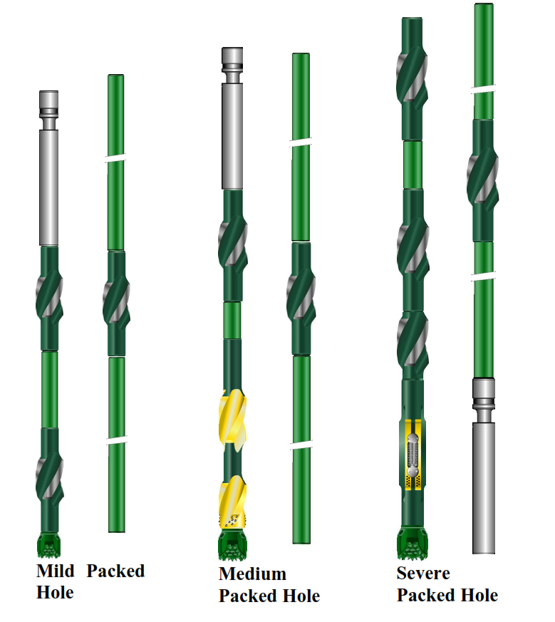
This technique seeks to prevent further wellbore deviation by preventing displacement of the assembly from the centre line of the hole. Progressive application of the principle would involve:
- the use of drill collars with the largest practicable outside diameter.
- using a high concentration of stabilisers.
- using square drill collars (the maximum development of the first two points) having a diagonal dimension equal to the bit size.
Square drill collars are effective in hard rock when natural deviating effects are severe, but they can be difficult to trip, liable to stick, and most difficult to fish.
Packed-hole assemblies minimise deviating (direction) trends, but it will be difficult to bring inclination back. In addition the minimum annular clearance substantially increase swabbing risks, overpulls, and the chances of sticking the tools; also extra handling time is involved on the rig floor.
Minor Effect On Inclination
The factors described above consider the composition of the assembly, formation effects, and weight-on-bit. Varying the other drilling conditions, particularly rotary speed and bit hydraulics, may also influence the behaviour of the assembly.
Such effects are difficult to predict or quantify, but in general terms, if more hole is made due to increased RPMs or bit hydraulics, then the same magnitude of directional deflection will be achieved by the bit over a longer drilled interval. Therefore the rate of inclination change (dogleg severity) will be reduced. Conversely, reducing the rate of penetration by using less rotary speed or hydraulics will tend to increase the wellbore deviation rate.
When it is essential to keep the inclination of a vertical hole within tight limits, and the techniques described are not sufficiently effective, the only alternative remaining is to employ corrective directional drilling methods.