Planning & calculating a horizontal wellbore differs from planning normal directional drilling wells for oil and gas. In a typical directional wellbore, the target is usually described as a departure at a certain TVD. The target has tolerances in the horizontal plane (North and East). In a horizontal well, the target is commonly described by the TVD plus or minus a tolerance. The departure target is usually more flexible than the TVD target. If the horizontal well also has a tight departure target, drilling is more difficult.
For example, a formation top may be at a true vertical depth of 4,000 feet, and the formation is 20 feet thick. Placing a horizontal well in this formation will require the wellbore to be horizontal at a TVD of 4,010 feet, plus or minus ten feet. Some horizontal wells have been drilled with a TVD target tolerance of plus or minus 1.5 feet. The wellbore must stay within a three-foot vertical zone. As you can see, target tolerances for horizontal wellbores are much smaller than typical directional oil/gas wells. Consequently, they are a little harder to hit, and greater care must be exercised in drilling a horizontal wellbore. dr
Horizontal Directional Drilling Planning Calculations Steps
Gathering Data
The first step in planning a horizontal wellbore is to gather all the information possible about the well and the formation to be drilled. Available data from offset wells, even vertical wells, should be collected. Items of interest are well logs, bit records, mud logs, directional data, daily reports, and any other data that might be helpful. Even vertical offset wells can provide valuable information for drilling a horizontal well, including target depths. There are few horizontal exploratory wells; therefore, offset well information is always available.
Indicate The Reason Of Horizontal Directional Drilling
The reason for drilling the horizontal wellbore must be defined. Is the horizontal well drilled to prevent water or gas coning or to intersect vertical fractures? The reason for drilling the horizontal well often drives the completion, which drives the drilling program. The type of completion must always be considered in horizontal well planning.
Target Geology
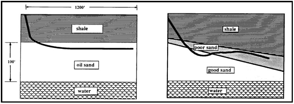
The geology of the target is significant. Remember, TVD targets can be very small, and bed dip is a major consideration. A bed dip of only two or three degrees can cause the horizontal wellbore to fall outside the target interval in only a short distance. Also, the geology of a formation can be slightly more complicated than originally expected. Figure 1 shows what can happen in a horizontal oil/gas well. The left side of the figure was the planned wellbore path and geology. The right side is the actual wellbore path and geology. The actual conditions in the formation did not match the predicted conditions. As a result, the operator ended up with a poor horizontal well. Knowing the exact geology of the formation is extremely important.
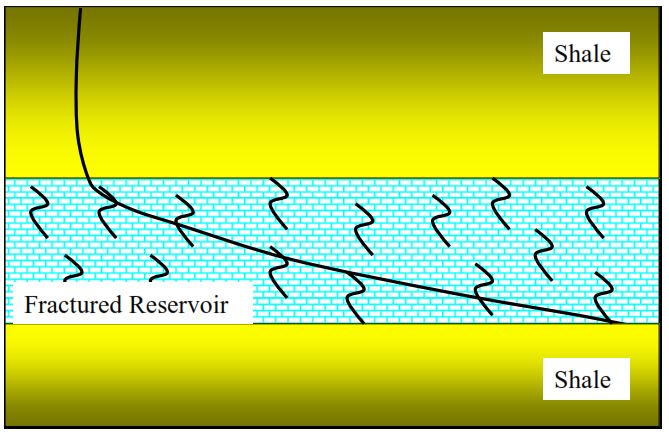
Calculating or planning a directional horizontal wellbore path must consider all the geologic constraints in drilling. It must also take into consideration the reason for drilling the horizontal well. If the well is drilled to prevent water coning, the wellbore will be placed away from the water near the top of the producing interval. Gas coning requires the well to be placed near the bottom of the producing interval. If the well is being drilled to intersect natural fractures, the wellbore may be drilled from the top of the reservoir at the end of the build curve to the bottom of the formation at the end of the horizontal section, as shown in Figure 2.
It may also be that the geology of the formations is not precisely known. The planning may require the formation to be drilled vertically, logged, and/or cored before drilling horizontally. The vertical well or pilot hole defines the target TVD and provides information about the lithology changes within the formation. Then, the wellbore is plugged back, sidetracked (also check: sidetracking well), and drilled horizontally in a more favorable position.
Remember, a lot of money is being spent to drill the well horizontally. If the geologic data is inadequate, the chances of a commercially viable horizontal wellbore decrease significantly.
Casing Seat Calculation For Directional Horizontal Drilling
Once the target constraints have been defined, the wellbore must be planned. Review the offset data to determine where the casing must be set (Casing Setting Depth). Decide what bit size will be required to drill the horizontal section. In many horizontal wells, the casing is set through the build curve to eliminate any potential problems with formations above the pay zone. However, casing set through the build curve is not a requirement. It depends upon the stability of the formations above the pay zone and the completion method. The horizontal oil/gas well takes longer to drill than a vertical well. Formations above the pay zone may deteriorate with time. Even though these formations may not be a problem in a vertical well, they may start to be a problem due to the longer drilling time in a horizontal well. Each well must be considered individually.
Open Hole Or Liner Completion?
If the horizontal oil/gas drilling well is to be completed open hole or with a slotted casing liner, water-producing formations above the pay zone may have to be cased. They can be cased before drilling the horizontal section or after the horizontal section is drilled. Casing the section after the horizontal portion has been drilled will require running an external casing packer for isolation and cementing above the packer. In open-hole completions, the formation above the pay zone may not be stable over a long period. For example, a horizontal well must be drilled in a limestone formation. The limestone is sufficiently stable to allow an open hole completion. However, the shale section immediately above the limestone may not be stable and must be cased.
Horizontal directional Drilling Calculations
Planning the build rate has to take several considerations into account.
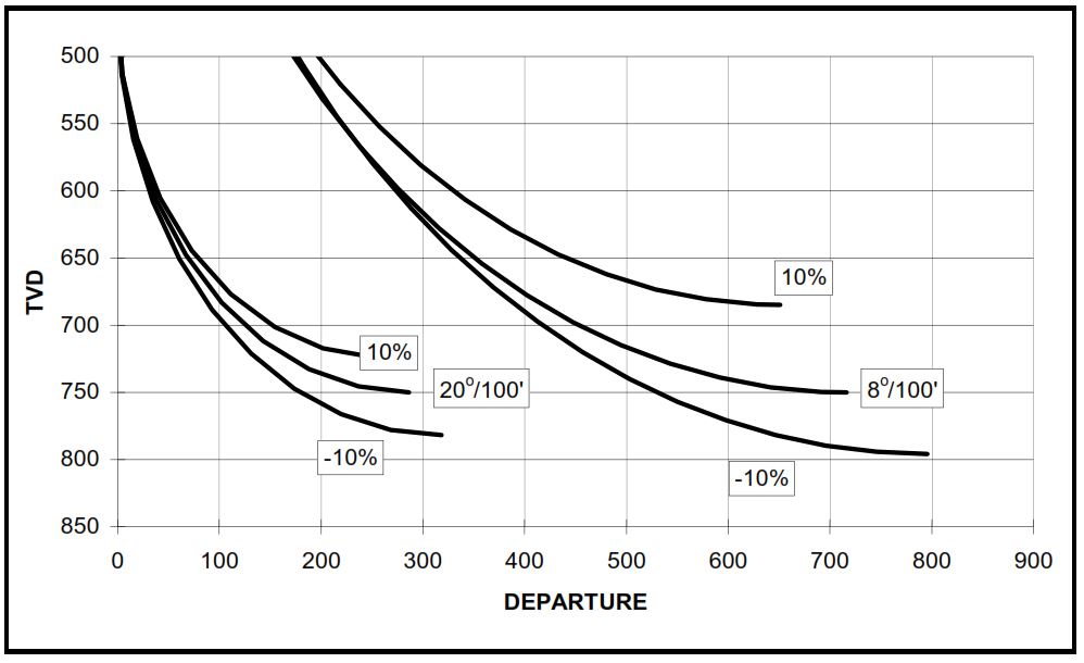
- Firstly, long-radius builds are time-consuming and more expensive, and it is more difficult to hit the desired TVD target unless drilled with a steerable system. Figure 3 shows how the TVD of the wellbore will change when the actual build rate is ±10% of the planned build rate. A long radius is not used very often on land wells. A long radius is the method of choice in most offshore applications because it can be used when the departure of the horizontal wellbore needs to be farther away from the surface location.
- Secondly, Short radius build rates make it easier to hit the target but bending stresses in tubular and restrictions around a curve limit drilling and completion alternatives. Also, the short radius build will yield the shortest horizontal wellbore length. A short radius is more frequently used when sidetracking out of an existing wellbore.
- Thirdly, a Medium radius is a compromise between the long and short radius. It uses near conventional equipment, allows hitting smaller target intervals, is not relatively costly, and allows most completion options. A medium radius is preferred for most horizontal drilling oil/gas wells.
Remember : Each method has its applications.
Build Up Rate
The actual build rate is usually based on preference or available kickoff points. Typically, higher build rates are used in smaller-diameter holes, and lower build rates are used in larger-diameter holes. The dogleg severity limit to prevent fatigue of 4½ inch drill pipe is about 18º/100 feet, whereas the limit for 3½ inch drill pipe is 24º/100 feet. Above these limits, fatigue can be a problem, although the drill pipe can still be rotated at higher dogleg severities. Also, the tools used to build inclination cannot build as fast in a large-diameter hole as in a small-diameter hole.
- An 8½-inch hole is limited to 15 to 18º/100-foot build rates depending on the motor configuration used. There are intermediate radius tools available that can build up to 50º/100’.
- A 6-inch hole is limited to about a 25º/100-foot build rate, though some short radius tools are now available for higher build rates.
- The maximum build rate for a 12¼-inch hole will be about 12 to 14º/100 feet. There are always exceptions to the above numbers.
The operator must decide in his calculation of horizontal directional drilling upon what build rate to use. Generally, the higher build rates will yield less time drilling and, therefore, less cost. The build rate may also be determined by hole problems or casing setting depths. In either case, the operator selects the build rate or kickoff point. If the kickoff point is selected, the build rate is calculated, and vice versa.
In most offshore rig applications, the operator must do the necessary calculations to drill a directional well to get to the portion of the reservoir where the horizontal needs to be located. Therefore, most offshore horizontal drilling oil-gas wells are directionally drilled with the calculation of long radius or lower build rates.
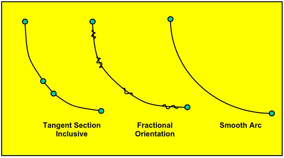
When the target requirements are small, adjusting the build curve to hit the intended target may be necessary. Nowadays, the build rate of most motor assemblies is predictable to within ten to fifteen percent. The build rates are even more predictable with previous experience in a specific area. In areas with little experience drilling horizontal wells, planning the well with a tangent section, fractional orientation, or soft landing is not uncommon. A tangent section is a short portion of the build curve drilled at a relatively constant inclination, as shown in Figure 4. For example, the wellbore may build inclination at 12º/100 feet to 45º. Then, a 100-foot section is drilled at 45º before continuing to build inclination at 12º/100 feet.
Tangent Section
The tangent section allows for differences between planned and actual build rates. If the build rate exceeds the planned build rate, the well reaches 90º too deep. If it exceeds the planned rate, the wellbore will reach 90º too shallow, as shown in Figure 3. The tangent section can be used to compensate for the differences. If the build rate exceeds anticipated, the tangent section can be lengthened to consume more TVD. Conversely, if the build rate is less than anticipated, the tangent section is shortened, providing more TVD to work with.
At one time, planning a tangent section for a medium radius horizontal well was widespread, but they are not as common as they used to be. Tangent sections are not needed for wells with large TVD targets. A tangent section is not used in areas where the build rate of a motor assembly has been demonstrated through experience. Tangent sections cost money if the drill string has to be tripped to drill the tangent section and should be avoided if possible. Drilling the tangent section requires two trips unless the build curve is drilled with a steerable mud motor assembly. On the first trip, the angle build assembly is pulled from the hole, and an assembly is run to drill the tangent section. At the end of the tangent section, the assembly is pulled, and the angle builds assembly run to continue building inclination.
Avoiding Tangent Section
A tangent section can be avoided by running a steerable motor assembly capable of building the desired build rates. A curve with a steerable motor assembly is designed to build at a higher rate than the planned rate. As the inclination increases, the assembly can be rotated to drill small tangent sections in the build curve as required. This is normally termed fractional orientation, as illustrated in Figure 4. No tripping pipe or trip is made to change the assembly, resulting in cost savings. Unfortunately, higher build rates cannot be obtained with a steerable system or rotary steerable system. Some motor assemblies can be rotated at the lower end of the medium radius.
If the build rate of the medium radius motor has been demonstrated through experience in the area, a tangent section can be deleted. Most operators will kick off slightly higher than necessary to hit the TVD target. The assembly drills ahead, building inclination close to but slightly ahead of the planned rate. While drilling the build curve, the motor can be alternately oriented left and right to kill some build rates. If the toolface is not pointed to the high side, the build rate will decrease even though the dogleg severity is the same. It does, however, change the direction of the wellbore. That is why the motor must be alternately oriented left and right. The change in direction caused by drilling with the toolface to the left of the high side will be canceled by orienting the toolface to the right and drilling a comparable length of the hole. The number of holes drilled with the toolface oriented to the left and right of the high side must be calculated based on the toolface setting.
Take The Decision
The operator must decide whether or not to put a tangent section in the build curve. That decision must be based on experience with the equipment and target tolerances. The tangent section is a more conservative approach but is also more expensive if additional trips must be made to drill the tangent section. If the build section can be drilled with a steerable motor assembly or rotary steerable, the tangent section is one of the most economical alternatives.
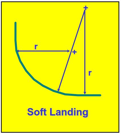
Soft Landing
Another alternative is to use what is termed a soft landing. Figure 5 illustrates a soft landing. A higher build rate is used in the first 70 o to 75o. Then, a steerable system is run in the hole, and the last portion of the well is drilled at a lower rate. The soft landing will yield higher departures since departure is significantly above 70.
The Team Required For Horizontal Directional Drilling Planning & Calculations
As should be evident, directional horizontal drilling calculations & planning is a multi-disciplined project. Horizontal planning must include personnel from
- Geology
- Drilling
- Reservoir
- Production and
- Service Companies
The effect of geology on the horizontal drilling of oil/gas wells has already been discussed. The reservoir and production personnel should be involved in the planning. Certain reservoir portions may be where the horizontal wellbore will be more effective. What are the pressures within the section that the horizontal well will penetrate? What kind of formation damage can be expected from the drilling fluid? Will the horizontal wellbore require stimulation to produce effectively? Will the well have to be produced using the artificial lift, and what volumes can be expected? Many questions must be answered before the drilling plan can be finalized, and the reservoir and production groups will have to help answer these questions.
Service company personnel must be involved in the planning phase. They have more experience with their equipment than anyone and can help the operator during the planning phase. It is best to know the limits of the equipment before the drilling operations begin. This includes the equipment used to drill the well and the equipment used to complete the horizontal drilling oil/gas well. It has been said many times that “failing to plan is the same as planning to fail.” In horizontal drilling, this is certainly true. Planning and calculations are among the most important steps in drilling a directional horizontal well.
How To Do Horizontal Directional Drilling Calculation Planning
Certain information is required in planning any directional well profile (Check well trajectory calculation), . Horizontal drilling is no different. As stated earlier, the critical target for a horizontal well is usually a TVD target, and the departure is seldom as critical unless drilled from a platform (platform rigs) or pad. With a platform or pad, the wellbore must first reach the reservoir portion where the horizontal oil/gas well will be placed. In that case, the upper portion of the well is drilled like a normal directional well, and the lower portion is drilled like a normal horizontal oil/gas well.
Additionally, in offshore applications, the azimuth required to get to the portion of the reservoir where the horizontal will be located is usually not the same as the horizontal azimuth. However, the same can be true when drilling a horizontal well onshore. The final build will also include a turn. Generally, planning the directional drilling profile is a trial-and-error process if the equations in this article are used. However, many good computer programs can do three-dimensional planning. It is just beyond the scope of this article.
In horizontal drilling, the kickoff point or the build rate must be specified to plan & do the calculation of the directional horizontal oil/gas well. Usually, the inclination of the horizontal section is determined by bed dip and thickness. Example 1 illustrates planning a horizontal wellbore.
First Example
Given:
- A horizontal well with a TVD target of 4,800 feet
- The build rate is 12º/100 feet
- The tangent section at 60º
- The tangent section will be 50 feet of TVD.
Determine:
Calculate the kickoff point for this horizontal oil/gas well.
Solution:
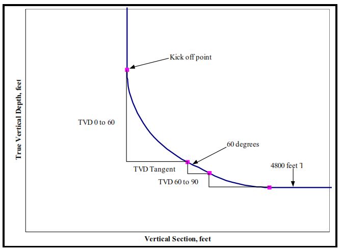
The first action should be to draw a picture of the well, as shown in Figure 6. Once a picture has been drawn, determine the available information and what can be calculated. First, the TVD of the tangent section was given as 50 feet. All that remains to calculate the kickoff point is the TVD from 0 to 60 degrees and from 60 to 90 degrees. These can be calculated using the radius of curvature equations or the 12-degree build-up table provided at the end of the article.
TVD 0 to 60 degrees
I2-I1
Δ MD = ———-
Br
Δ MD = (60-0) / (12/100) = 500 ft
(180) Δ MD ( sin I2 – sin I1)
Δ TVD = ——————————–
π (I2 – I1)
Δ TVD = 180 x 500 x (sin 60 – sin 0) / π ( 60- 0 ) = 413.5 ft
TVD 60 to 90 degrees
I2-I1
Δ MD = ———-
Br
Δ MD = (90-60) / (12/100) = 250 ft
(180) Δ MD ( sin I2 – sin I1)
Δ TVD = ——————————–
π (I2 – I1)
Δ TVD = 180 x 250x (sin 90 – sin 60) / π ( 90 – 60 ) = 63.97 ft
Since the TVD of the tangent section is 50 feet, the kickoff point can be calculated by subtracting the TVD of each section from the target TVD:
Kickoff Point = TVD Target- TVD 0 to 60 – TVD Tangent – TVD 60 to 90
Kickoff Point = 4,800 – 413.50 – 50 – 63.97 = 4,272.53 feet
Second Example Considering Bed Dips
When bed dips are considered, calculation & planning the horizontal directional drilling oil/gas well can be more complicated. The inclination of the horizontal section will be a function of the apparent bed dip in the plane the well is being drilled. It is not the bed dip perpendicular to the bed strike. Generally, the apparent dip can be obtained from the geology department. The inclination of the horizontal section also depends upon the position of the horizontal section within the producing formation.
If the well is to be drilled from top to bottom, as shown in Figure 2, the inclination of the horizontal section will be different from the apparent bed dip. The second example illustrates calculating the kickoff point and horizontal inclination with bed dip drilling from the top to the bottom of the producing formation.
Given:
- The apparent dip of formation in the plane of horizontal is 5º
- The well is to drill down dip.
- The build rate is 14º/100 feet
- Bed thickness is 50 feet
- TVD of the target directly below the surface location is 4,000 feet.
- Want to drill from the top of the formation to the bottom of the formation in 2,000 feet of horizontal section
Determine:
- The inclination of the horizontal section.
- The kickoff point.
Solution:
It is best to draw a picture, as represented in Figure 7, to simplify the calculation of horizontal directional drilling. This figure is not drawn to scale, so differences in angles can be seen. Note that the TVD where the horizontal wellbore enters the producing formation is not the same as the TVD of the producing formation at the surface location. The TVD where the wellbore enters the formation must be calculated.
Determine the inclination of the horizontal section based on the 5º bed dip and drilling from top to bottom of the producing formation. From Figure 7, it can be seen that the inclination of the horizontal section must be less than 85 degrees.
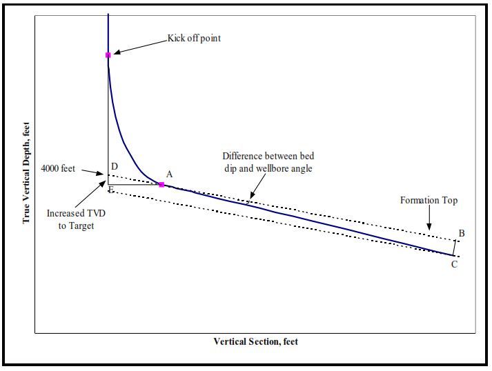
A right triangle can be seen as described by the points “ABC.” Angle “A” is the difference between the bed dip and the inclination of the wellbore. The hypotenuse length is the length of the horizontal section, which is 2,000 feet. Side “BC” is the thickness of the formation, which is 50 feet. The sine can be used to determine the angle “A.”
BC
A = sin-1 x —–
AC
A = sin-1 x 50 / 2000 = 1.43o
The inclination of the horizontal section would be:
90 – 5 – 1.43 = 83.57º
Five degrees is used as the bed dip because the inclination is measured from the vertical and bed dip from the horizontal.
The true vertical depth of the target will change as the wellbore moves away from the surface location. The right triangle, “ADE” represents the difference between TVD and DEP. Side “AE” is the departure, and side “DE” is the increased TVD to the target. Side “AE” is the departure to get to 83.57º. It can be calculated using the radius of curvature equations or interpolating in the build-up charts.
I2-I1
Δ MD = ———-
Br
Δ MD = (83.57-0) / (14/100) = 596.93 ft
(180) Δ MD ( cos I1 – cos I2)
Δ DEP = ——————————–
π (I2 – I1)
Δ DEP = 180 x 596.93 x (cos 0 – cos 83.57) / π ( 83.57 – 0 ) = 363.42 ft
Angle “A” in the right triangle is still related to the dip and is five degrees. Since one side and angle is known, the length of side “DE” can be determined based on the tangent of angle “A.”
DE
tan A = ——
AE
DE = tan A x AE
DE = tan 5 x 363.42 = 31.80 ft
So the target depth will be 31.80 feet deeper than the target depth at the surface location. Therefore, the target depth is 4,031.80 feet. The change in TVD required to go from vertical to 83.57 degrees can be calculated using the radius of curvature calculations as follows:
(180) Δ MD ( sin I2 – sin I1)
Δ TVD = ——————————–
π (I2 – I1)
Δ TVD = 180 x 596.93 x (sin 83.57 – sin 0) / π ( 83.57- 0 ) = 406.68 ft
The kickoff point can then be calculated as follows:
Kickoff point = TVD Target – TVD 0 to 83.57
Kickoff point = 4,031.80 – 406.68 = 3,625.12 feet