Mudline Suspension Systems (MLS) are commonly used for jack-up and platform drilling, where the elevation of the drill floor above the sea bed would impose unacceptable buckling forces on the unsupported casing type above the sea bed if the weight of the casing pipes were supported by a surface wellhead. MLS allows hanging off the casing weight at the sea bed instead of at the surface, while the casing strings are tied back to a conventional surface wellhead and BOP system.
Advantages
The following advantages are gained:
- The buckling load of each casing string will not be transmitted to the unsupported section of the previous casing string extending from the sea bed to the surface.
- It allows a simple and effective means of temporarily abandoning a well at the sea bed, which may subsequently be re-entered and completed either as a sub-sea well or tied back to a newly installed production platform.
- Abandonment of the well is greatly simplified.
- A conventional surface wellhead and BOP system can be utilized. The stack is accessible and has short choke and kill lines, allowing the same well control procedures as on land drilling rigs.
Having run landed and cemented a casing string, the annulus is sealed using a slip and seal assembly set in the surface wellhead. The surface wellhead is the same as that used in land operations. When a mudline suspension system is used, the only weight supported by the surface wellhead will be that of the casing between the surface wellhead and mudline, plus a small excess to prevent buckling.
Surface Tie-backs on a Jack-up
Several factors relating to well control must be considered when utilizing surface tie-backs on a jack-up. Although wellhead and BOP operations are greatly simplified compared to sub-sea operations from a floating rig, jack-up rigs will utilize a surface diverter system when drilling through the marine conductor and conductor string. This makes the rig extremely vulnerable in case of a shallow gas kick. Loss of well control and subsequent handling of large amounts of gas at the surface and possible sea bed cratering around the well can, and on several occasions, have caused the total loss of the rig with the associated danger to life. Stability is immediately lost when cratering extends to the rig supporting area. A floating rig drilling with returns at the sea bed could move off location in this situation, but a bottom-supported rig does not have this option.
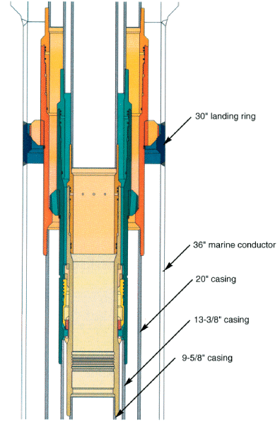
DRIL-QUIP MS-15 MLS System
There are two basic mudline suspension system designs: the ‘stack-up’ and ‘stack-down,’ each with its advantages and disadvantages. The stack-down system became the most popular among the two and has the following advantages:
- Each tieback thread and seal area is fully exposed, making tieback operations simple and minimizing the chance of damage.
- Tiebacks can be individually tested.
- Each set of washout ports is lower than on the previous casing string, ensuring no cement in the hanger area.
- Every temporary abandonment cap is fully covered by the subsequent cap.
Several manufacturers produce MLS. The operational features of a typical MLS system based on the Drill Quip MS-15 system (see Figure 1) will be discussed below as an example. Please refer to the manufacturer’s literature for detailed information on the actual system in use on your rig.
Marine Conductor Operations
When using the mudline suspension system, it is essential to accurately position the first hang-off shoulder at a predetermined position near the sea bed, usually 6-7 m (20-25 ft) below the mudline, to assist later abandonment. However, if the marine conductor is driven, it is impossible to predict its final penetration, making it impossible to run a hang-off shoulder to the required depth. In this case, the hang-off shoulder can be left out of the driven pipe and run with the subsequent string (the conductor string), which can be run to the required depth and cemented in place with the correct space out. If the well needs to be suspended or abandoned at the sea bed after drilling, then the extension of the marine conductor from the sea bed to the surface needs to be cut by divers.
Alternatively, the marine conductor can be run and cemented in place in a pre-drilled hole, allowing it to be spaced out and the MLS hang-off shoulder to be positioned at the correct depth. Removal of the marine conductor after drilling must also be done with diver assistance. Still, it can be simplified by running a quick-release conductor connector above the hang-off sub. Conductors with an OD of 20″ or smaller have a running/tie-back thread that can be backed out from the rig floor, eliminating the need for diver assistance during abandonment.
Mudline Suspension System Operations
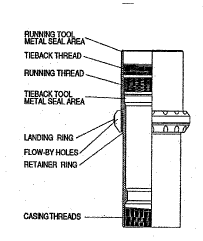
The MS-15 system utilizes two different types of hangers: the shoulder type (Figure 2) and the expanding split ring hanger (Figure 3).
Shoulder Type
The shoulder-type hanger lands on a butt-weld shoulder welded into the previous casing string or a matching shoulder profile in the previous hanger. This design is used where annular clearance between casing strings is large and provides a high load capacity and centralization while maintaining a large flow by area for circulation.
Expanding Split Ring Type
The expanding split ring hanger is utilized where annular clearance is small (i.e., smaller casing sizes) and located into a special profile that is machined into the bore of the previous hanger. It also provides a high load capacity at the split ring/hanger interface by providing full circumference bearing while maintaining a flow by area for cuttings. The detent ring design eliminates premature vertical movement of the split ring and provides automatic re-setting while eliminating troublesome shear pins. Both types of hangers only support the weight of the casing strings. Annular access and seals are provided by the surface wellhead.
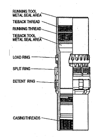
Figure 3: Split ring hanger
Clean Out Tool For Mudline Suspension System
When a split ring hanger is to be run, it is recommended to clean the landing profile in the previous casing at the mudline with a hanger profile clean-out tool (see Figure 4). Although the split ring hanger profile mechanism is designed to land and support the casing, even if there is some debris in the profile, it can not land if the profile is so full of cement or gumbo that the spilt ring can not expand into the profile.
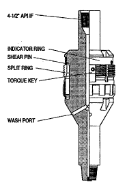
The hanger profile clean-out tool can be run on drill pipe and provides a thorough and complete clearing of the profile using clean-out dogs that match the landing profile and wash ports. Once the dogs lock into the landing profile, indicating complete cleanout, a shear ring moves upwards into a small groove. This position of the shear ring verifies complete clean-out after retrieval of the tool to the surface.
Casing Running Operations
Running casing is done conventionally, and the hanger and a running tool (Figure 5) are made up at the correct depth in the casing string. All casing thread connections above the running tool in the landing string should be torqued to the maximum allowable torque and/or should be tag welded. This is necessary due to the requirement to apply a certain amount of left-hand rotation to this running string to wash out the annular area after the cementation.
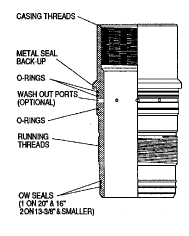
Figure 5: Casing running tool
The landing string is lowered into the hole until the hanger lands into the previous hanger. A weight loss of 20 – 30,000 lbs will be observed when using a split ring type hanger as the detent ring is depressed. The weight loss will be regained, and the pipe will travel 1 1/2″ downward until the split ring engages the hanger profile. The inner body forces the split ring into full engagement with the outer hanger and provides for positive backup of the split ring. No rotation or lifting is required, and full string weight can now be set on the hanger. The casing can then be cemented (without reciprocation) by using a conventional cement head installed on the running string at the surface.
Cement Displacement
Cement returns above the mudline suspension system housing and possible settling of solids from the fluid in the annulus between the sea bed and surface may interfere with future tie-back operations and must be washed out. The right-hand rotation of the running string (6 turns) opens the left-hand 3-pitch square thread on the running tool, exposing the washout ports (see Figure 6). This allows displacement of any cement or drilling fluid in the annulus above the hanger until clear returns are observed. The wash ports are located approximately four inches apart and are machined at an angle to cause swirling action, virtually eliminating the chances of channeling. A cement retarder is sometimes spotted before closing the ports to combat cement expansion from below the hanger.
Washout Ports Seals
The seal below the washout ports is located sufficiently from the ports so that no cement returns can be washed into the threads. A one-way seal at the running tool’s bottom protects the tie-back seal areas. This seal stays engaged in the seal bore during the washout operation to keep well fluids from the thread. The wash ports can be closed by left-hand rotation (6 turns) of the running string until a low positive torque of 500 to 1000 ft-lbs over rotation has built up. Two resilient seals and a metal-to-metal seal are located above the wash ports to ensure re-sealing after wash out. Should the metal-to-metal seal be required between the running tool and casing hanger after closing the wash ports, then the make-up torque will be significantly higher. Hence, there is a requirement to lock the connections of the running string above.
Hanger running tools are, as an alternative, also available without wash ports to minimize possible problems associated with re-sealing after washing operations. In large-size annuli, it is then possible to run small-diameter tubing down the annulus to the mudline hanger for flushing. Again, cement retarders can be spotted above the hanger.
Surface Annular Seal
After closing the wash ports, the casing and running tool seal can be pressure tested to the required pressure. An annular seal can now be installed in the surface wellhead, depending on the type of wellhead. This will usually be a type AW or WC slip and seal assembly or equivalent. Type CA slips can not be used because they require weight to set the packing. This weight is unavailable as the running string is free-standing from the mudline up.
Mudline Suspension System Final Status
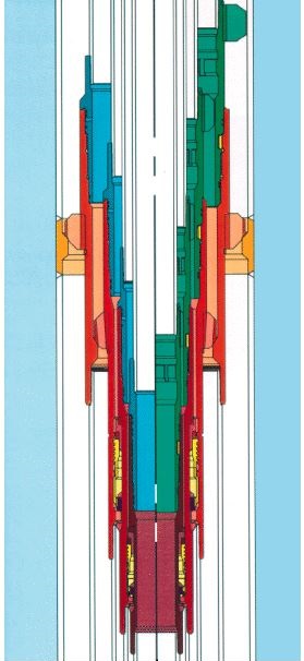
Subsequent casing strings are landed and cemented in a similar way, each mudline hanger ‘stacking down’ from the previous one, fully exposing the tie-back preparations and seal areas. The well can now be completed, abandoned, suspended or re-entered (see Figure 7).
A surface completion utilizes the surface wellhead and casing running strings extending from the mudline suspension system hangers at the sea bed to the surface wellhead, as installed during the drilling phase. The well can be completed with a tubing string and surface X-mas tree.
A subsurface completion requires the removal of the surface wellhead and casing running strings. The running strings can be retrieved with ten right-hand turns of the running string, which releases the running tools from the running thread above the hangers. A sub-sea completion now requires tailor-made conversion equipment to suit the planned completions and sub-sea X-mas tree requirements.
The well can also be abandoned or temporarily suspended at the sea bed. Abandonment is greatly simplified if the MLS hangers are positioned some 6-7 m (20-25 ft) below the sea bed so that no sub-sea obstructions remain after removing the surface wellhead and casing running strings. A sonar pinger and marker buoys can be attached to the well to assist in re-positioning a rig over the well at a later stage.
After setting the required abandonment plugs in the well, the blow-out preventers and upper casing spool can be removed. Then, the inner extension string is retrieved by backing off the running tool from the MLS hanger by 11 turns of right-hand rotation. The running thread now exposed in the MLS hanger can be used to install a Temporary Abandonment cap (T/A cap) covering the innermost casing string.
Mudline Suspension System T/A Caps
T/A caps are installed on the drill pipe with a J-slot running tool. The running tool is prepared with a centralizer to ensure centralization within the next larger running string, and all threads are designed to be fully aligned before thread contact, eliminating the possibility of cross-threading. Six or seven left-hand turns will install the cap, and not more than 500-1,000 lbs-ft of torque is required as there are no metal-to-metal seals to energize. Weight set stab-in T/A caps are available as an alternative, requiring only 1/4 turn to make-up.
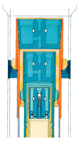
Subsequent caps can be installed after the corresponding casing spools and running strings are removed. Every T/A cap is completely covered by the next outer cap (see Figure 8) and has a vent port to avoid trapping pressure underneath. The innermost cap contains a back pressure valve to monitor and release trapped pressure from the production casing. The valve can be operated with a T/A cap running tool, venting pressure through the drill pipe without using a wireline.
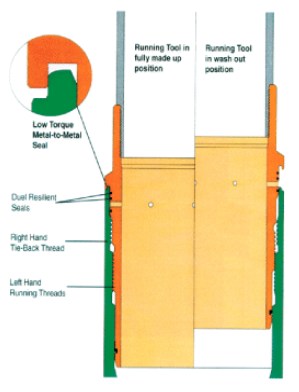
Temporary abandonment with T/A caps allows the well to be re-entered and tied back to the surface later. Removal of the caps exposes the right hand 2 or 3 pitch square tie-back threads in the mudline suspension system hanger, which are utilized to connect the tie-back casing strings to the surface. Tie-back tools can be a rotation set (7-8 right-hand turns) or a stab-and-lock set (weight set lock). The stabbing in tie-back tool will automatically lock into the tie-back profile threads and require a minimum of 5,000 lbs-ft right-hand torque to energize the metal seal.
Torque Tool
A torque tool that engages a torque slot in the stab-in tool can be run on a drill pipe to energize the metal seal, eliminating torque on the connections of the tie-back riser. Both tools have a metal-to-metal seal, two resilient seals to contain internal pressure, and two resilient seals to contain external pressure. The metal-to-metal seal preparations used by the tie-back tools are separate from the ones used by the running tools. Dedicated cleanout tools are available to assist in installing and removing T/A caps and clean-out tie-back profiles.