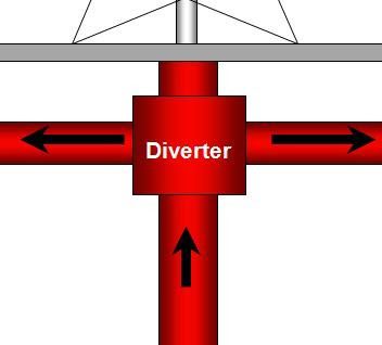
The function of a diverter system in oil and gas rigs (Check also types of drilling rigs) is to provide a low-pressure well flow control system to direct controlled or uncontrolled wellbore fluids or gas away from the immediate drilling area for the safety of personnel and equipment involved in the drilling operation. The diverter system is not designed to shut in or halt well flow.
Diverter system equipment that can be exposed to a hydrogen sulfide environment should comply with NACE MR-01-75: “Material Requirements Sulfide Stress Cracking Resistant Metallic Materials for Oil Field Equipment”, latest edition.
What Is The Main Application Of Diverter Drilling System on the Rig?
Where shallow casing strings or conductor casing pipes are set, fracture gradients will be low. It may be impossible to close the blowout preventer on a shallow gas kick without breaking down the formation at the casing setting depth (shoe). If a shallow gas kick is taken while drilling the top hole on the rig then the kick should be diverted through an oil and gas well control diverter system.
Drilling shallow sand too fast can result in large volumes of gas cut mud in the annulus and cause the well to flow, also fast drilling can load up the annulus increasing the Equivalent circulating density leading to lost circulation problems and if the level in the annulus drops far enough then well may flow which is considered one of the causes of kick.
When drilling the top hole a diverter should be installed and it is good practice to leave the diverter installed until 13 3/8″ casing has been run.
Aramco Well Control Manual
If any of the kick warning signs are observed while drilling the top hole, close the diverter immediately as the gas will reach the surface in a very short time and it is inadvisable to attempt a flow check.
Drilling Diverter System Usage In Well Control
Where shallow casing strings are set, fracture gradients are often very low and wells may not be able to be safely closed in on a kick without danger of lost circulation and possible broaching to the surface. Gas from shallow sands can be abnormally pressured, increasing the possibility of lost circulation and the possibility of vertical fracturing of shallow formations allowing formation fluids to vent to the surface outside of the drilled hole.
The time needed to get formation fluids to surface from shallow formations may be less than one minute. This short amount of time leaves the driller little time to react. It is absolutely necessary that the driller know the signs of and the appropriate actions to take in the event of a shallow gas kick.
Drilling shallow sands too rapidly can cause excessive gas-cutting of the drilling fluid with cuttings gas to the extent that expansion while being pumped to the surface lowers the hydrostatic pressure enough to cause formation flow because of the lack of Bottom-Hole pressure.
Conversely, large amounts of drilled cuttings in the drilling fluid from drilling at high rates of penetration may cause the drilling fluid density to increase to a point that circulation may be lost. When lost circulation occurs the level of fluid may fall in the well, causing the hydrostatic head to drop to a point that may allow the well to flow.
A drilling diverter system may be used in those areas with possible shallow gas sands to direct well flow away from the rig during kicks. the diverter should be arranged so that a diverter linc automatically opens or is open when the diverter is closed in order to divert the kick fluids and prevent back pressure on the hole.
Diversion is usually away from the rig, resulting in lost circulation of drilling fluid from the circulating system. Under these conditions, formation fluid flow continues during the well control operation until the hole bridges or hydrostatic pressure can be built enough to regain primary well control or until the formation is depleted.
Pumping at a fast rate tends to improve the drilling fluid/gas ratio and also creates a small increase in bottom-hole pressure due to annular friction pressure. Increasing the drilling fluid density at a fast rate increases hydrostatic pressure and may eventually stop flow. Thus, whoa a shallow gas flow occurs, the following actions should be taken immediately:
- Pump as fast as possible.
- Increase drilling fluid density as rapidly as possible while pumping.
- If drilling fluid supply should be exhausted, continue by pumping water.
- Divert the well fluids in a safe path away from the rig floor.
On large drilling rigs in areas with possible shallow gas, a reserve supply of drilling fluid weighted above the current mud weight may be carried in reserve for use in shallow gas kick remediation. Immediate pumping of a pre-weighted kill mud into the well by using wait and weight method, if shallow gas kick occurs, should be considered as part of a shallow-gas kick contingency plan.
If the drilling fluid supply is exhausted, a plug may be attempted. This procedure may serve to
- increase the hydrostatic pressure
- to form a super viscous pill,
- to form a fast hardening concrete pill depending on the plug type
Diverter System | Typical Operating Pressures Recommendations & Consideratrions
The diverter packer regulator will provide a maximum pressure of 1200 psi on the packer.
- For normal pressure use 750 psi.
The manifold pressure regulator provides a maximum pressure of 1650 psi.
- For normal operation do not exceed 1250 psi.
Recommended pressure settings generally are:
- Hydraulic supply pressure 3000 psi
- Manifold pressure 1250 psi
- Drilling Diverter System packer pressure 750 psi
Diverter System Components & Specifications
A diverter system is comprised of the following components:
Annular Sealing Device.
The annular sealing device is available in three different designs. These designs are:
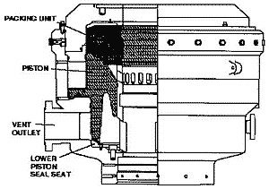
Annular Packing Element.
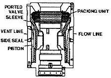
Figure 1 is an example of an annular sealing device that utilizes an annular packing element as the sealing mechanism.
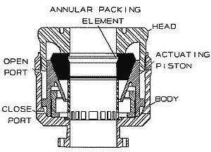
The annular packing element can affect a seal on any pipe or kelly size in the wellbore, or can affect a seal on open hole where no pipe is present. This is oftentimes referred to as “complete shut-off” (CSO).
Insert-type Packing Element.
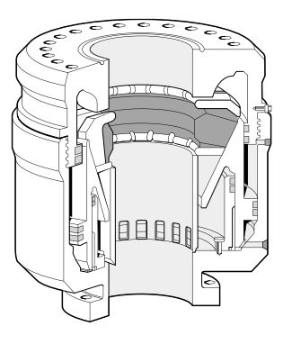
Figure 2 is an example of an annular sealing device that utilized an insert-type packing element as the sealing mechanism.
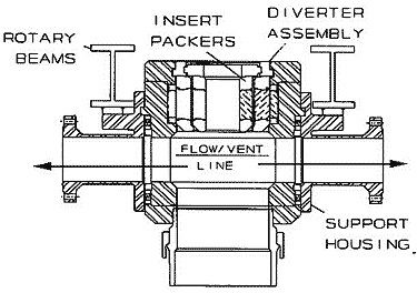
An insert-type packing diverter element uses a group of inserts. The inserts are placed one inside the other. Each insert in the group is designed to close and seal on different ranges of pipe diameters. A hydraulic or mechanical function serves to latch each insert in place. The correct size insert should be in place for the pipe size in use. In order to pass large bottom hole assemblies, it is necessary to remove some or all of the inserts. An insert-type packing element can not CSO.
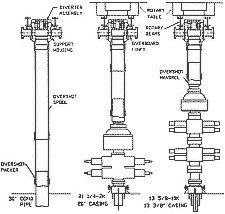
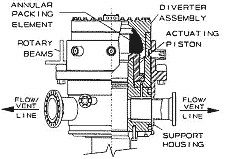
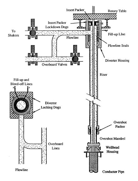
Rotating Head
A rotating head can be used as a drilling diverter to complement a blowout preventer system. The stripper rubber is energized by the wellbore pressure to seal the rotating head element against the drill pipe, kelly, or other pipe to facilitate diverting return wellbore media and can be used to permit pipe movement.
Vent Outlet(s)
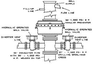
Vent outlet(s) for the oil and gas diverter system are located below the annular packing element. One or more vent outlets can be used in a system. Vent outlet(s) may either be incorporated in the housing of the annular sealing device or may be an integral part of a separate drilling spool/mud cross that is assembled using a flange or clamp type connection just below the annular sealing device.
Design considerations for the connection between the vent outlet(s) and the vent line(s) should include ease of installation, leak-free construction, and freedom from solids accumulation. Regarding the size of the vent outlet(s), different regulator bodies have different requirements, depending on the area of operation. For example, the requirements for drilling operations that utilize a surface wellhead configuration in areas regulated by the U.S. Minerals Management Service (reference CFR 30, Chapter II, 7-1-88 Edition, paragraph 250.59) require that no spool outlet or drilling diverter line shall have an internal diameter less than 10 inches; except in the case where dual outlets are provided, in which case the minimum internal diameter of each vent outlet is 8 inches. For drilling operations where a floating or semi-submersible type drilling vessel is used, the vent outlet internal diameter shall not be less than 12 inches. For drilling activity outside the United States, the drilling contractor is advised to become familiar with the regulations for that particular area of operation.
Drilling Spool/Mud Cross.
If a drilling spool/mud cross is utilized under the annular scaling device, the through bore diameter of the drilling spool/mud cross should be equal to the through-bore diameter of the diverter annular sealing device. The design working pressure rating of the drilling spool/mud cross should be equal to the design working pressure rating of the annular sealing device.
Valves
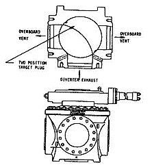
Valves used in a diverter vent line(s), or in the flow line to the shale shaker in a floating drilling operation, should be full-opening, have at least the same through-bore opening as the vent outlet that it is attached to, and should be capable of opening with maximum anticipated pressure across the valve sealing mechanism. Several types of full-opening valves which can be used in this application are gate valves (various types), ball valves, knife valves, switchable three-way targeted valves (see Figure K1-3F), and valves that are integral to the annular sealing device.
Any valve used in oil and gas diverter system application should be fitted with remote actuators capable of operation from the drilling rig floor. The actuators can be operated either with hydraulics or pneumatics. The actuator should be sized to open the valve with the maximum system rated working pressure across the closed valve sealing mechanism, with hydraulic or pneumatic pressure that is available from the diverter system remote control unit. The trim of the internal components of the valve actuator should be suitable for the media that is going to be used to operate the actuator. If a water-based fluid is the media, the actuator trim should be suitable for water service; corrosive. Excessive resistance due to drilled solids in the valve should be kept in mind, especially if using a pneumatic system where variations in rig air pressure are common.
Vent Line Piping.
There are various considerations that need to be investigated for the vent line piping in a drilling diverter system. These considerations are as follows:
Sizing
The vent line piping in a diverter system should be sized to minimize back pressure on the wellbore while diverting wellbore media. The vent line should be run as straight as possible, keeping in mind that bends, tees, and elbows not only create higher back pressure than straight pipe, but are more susceptible to erosion during a diverting operation than straight piping. Just as with the vent outlet(s) discussed in the above paragraph, government regula- tory bodies have minimum requirements for the internal diameter of the vent line piping. The drilling contractor should be familiar with the requirements for the area where the drilling operation is going to take place.
Flexible Lines
Flexible lines with integral end couplings can be employed in a diverter vent line piping system. If used, the flexible lines should have the same or larger internal diameter as the vent outlet and valve, they should be resistant to fire and erosion, have end couplings that are compatible with those utilized in the hard piped section(s) of the vent line piping system, and supported adequately.
Routing
The vent line(s) used in a diverter system should be routed so that at all times one line can vent wellbore media to the downwind side of the oil and gas rig. Routing changes should be as gradual as possible. Long radius bends are preferred over short radius bends. In the ease of a 90
Drilling Diverter Types
Diverter Types Brief Description:
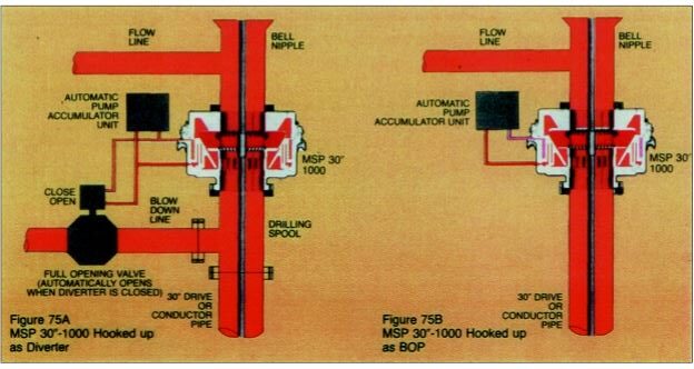
Hydril MSP
NORMAL AUTO SEQUENCE:
Placing the diverter packer control valve in the close position automatically opens the pre-selected overboard valve.
NORMAL SAFETY INTERLOCK:
Hydraulic pressure to close the diverter packer is prevented until at least one overboard control valve has been shifted to open.
OPERATING FEATURES
- Will close on open hole and hold 2000 psi (but not recommended).
- Primary usage is in diverter systems.
- Automatically returns to the open position when closing is released.
- Sealing assistance is gained from the well pressure.
- Greater stripping operations capability of the packing unit since (fatigue) wear occurson the outside of the packing unit.
Vetco KFL
NORMAL AUTO SEQUENCE:
Placing the diverter packer control valve in the close position automatically opens the pre-selected overboard valve and locks The insert packer.
NORMAL SAFETY INTERLOCK:
Hydraulic pressure to close the diverter packer is prevented until at least one overboard control valve has been shifted to open and the insert packer control valve has been shifted to lock.
Hydril FSP
NORMAL AUTO SEQUENCE:
Not required in the control system. NORMAL SAFETY INTERLOCK — Not required in the control system.
NOTE: The FSP diverter is designed so that when the piston moves up to close the diverter packer closing the flow line out of the top mounted bell nipple, it clears the bottom outlet to the vent line which is blocked when the piston is down (diverter packer open). The vent line cannot be closed. There is a selector deflector to select port or starboard.
Vetco KFDJ
NORMAL AUTO SEQUENCE:
Placing the diverter packer control valve in the close position automatically shifts The pre-selected overboard control valve to the open position, and ensures The inflowing valves shifts to the position indicated if they are rot already in that position:
| Insert Packer | Lock |
| Diverter Lock Dogs | Lock |
| Flowline Seals | Pressurized |
| Overshot Packer | Pressurized |
| Flowline / shaker Valve | Close |
| Drilling Trip Tank Valve | Close (if applicable) |
| Fill-Up Valve | Close (if applicable) |
NORMAL SAFETY INTERLOCKS:
Hydraulic pressure to close the diverter packer is prevented until the following pilot signals are sensed:
- At least one overboard valve has been actuated to open.
- The insert packer has been actuated to lock.
- Pressure is applied to both the flowline and overshot packer seals.
TIME DELAY CIRCUITS:
The following circuits should be designed so they can be overridden after a 10 to 60 second delay:
- Overboard valve can be shifted to port open / starboard close or starboard open / port close.
- Flowline valve can be opened or closed at the operators discretion.
- Trip tank valve can be opened or closed at the operators discretion.
- Drilling Riser fill valve can be opened or closed at the operators discretion.
NOTE: If overriding these functions is desired by the operator with the overboard valves closed, the diverter-test valve can be placed in the test position interrupting the auto sequence. This is normally required for low pressure testing of the diverter lines.
Additional Features Common To Platform Diverters:
- Safety circuit to prevent venting the flowline seals or overshot packer when the diverter packer is closed.
- Optional divert/strip function.
- Divert/test mode function allows closing all diverter functions for low pressure testing.
- Low deadband failsafe pneumatic motor driven remote controlled regulators. Normally only the diverter packer pressure regulator is remotely operated. All regulators can be remotely operated. Remotely operated regulators should be sensitive to down stream pressure changes within plus/minus 150 psi.
- KFDJ and KFDS diverter control systems should include a “Diverter Ready” indicator to indicate when the safety interlock circuits have been preset to their proper position.
- Hydraulic safety logic should be used to reduce the dependence on pneumatic circuitry.
- Pneumatic circuits should be minimized for safety. Air supply for a minimum of two times the volume to se- quence the diverter controls should be check, valved in and stored in the panel for emergency operation.
- Low air supply pressure and low hydraulic supply pressure warning lights should be included in diverter control systems with electric remote control. Function position status indication should also be included.
Vetco KFDS
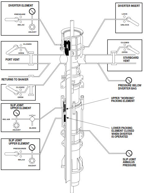
The normal auto sequence, safety interlocks, delay circuits and additional features described in the KFDJ diverter brief descriptions are generally applicable to the KFDS diverter controls for subsea systems. KFDS systems usually have more hydraulic functions than the KFDJ and will include a slip joint packer which may be energized by air or hydraulic pressure.
Automatic Diverter Drilling System
An automatic diverter system should first:-
- Open an alternative flow path to overboard lines.
- Close shaker valve and trip tank valve.
- Close diverter annular around drill pipe.
- If there are two overboard lines then the upwind valve should be manually closed.
The Diverting Procedure in Well Control
Suggested diverting procedures in the event of a shallow gas kick (well control) on oil and gas drilling rig are as following:
- Maintain maximum pump rate and commence pumping kill mud if available.
- Space out so that the lower safety valve is above the drill floor.
- With drilling diverter line open-close shaker valve and diverter system packer.
- Shut down all nonessential equipment, if there is an indication of gas on rig floor or cellar area then activate deluge systems.
- On jack-up rigs and platform rigs monitor sea for evidence of gas breaking out around the conductor.
- If mud reserves run out then continue pumping with sea water.
- While drilling top hole a float should be run. This will prevent gas from entering drill string if a kick is taken while making a connection. It will also stop backflow through the drill string on connections.
Diverter Remote Controls In Drilling Rigs
The master hydraulic diverter control manifold or control panel should be located off the drill floor in an area relatively safe from gas, fire, and falling debris and should be accessible to the drilling crew for operation in an emergency. This means that the diverter control functions should be capable of remote control from the driller’s location. On offshore drilling rigs, the control panel at the driller’s location should as a minimum include the following features:
- Control and status position indication of all diverter control functions.
- Control of the diverter packer regulator to increase/decrease function.
- Low hydraulic supply and low air supply to the master panel alarms. If the diverter control system is a “self- contained” unit, low reservoir level of the diverter control fluid reservoir should be included.
- Electric pump running light. (Self-contained units with electric pump.)
- “On battery power” indicator (units so equipped with emergency battery back-up).
- Nitrogen back-up initiated (if so equipped).
- Indication of all system pressures.
- Function controls oriented and represented in a graphic display of the diverter system.
The driller’s remote control panel should be designed in accordance with the recommendations of API RP16E.2.6 (see API RP16E.5.6). Driller panels should be suitable for installation in explosive gas environments.
Diverter control panels can frequently be incorporated with the B.O.P. control system panels to conserve space. Diverter functions should be electrically independent of the B.O.P. control functions.
Diverter Back-up Systems
The response time recommendation to sequence the diverter system and close the diverter packer within 30 seconds for diverter packers up to 20 inch nominal bore size and 45 seconds for diverter packers over 20 inch nominal bore size (Ref. API RP16E.5.1) can be met with a nitrogen back-up system or dedicated hydraulic BOP accumulators (Ref. API RP16E.5.3.2). The backup system can have manual intervention as long as it is selectable on-demand (remote control from the driller’s panel) or otherwise, automatic. Automatic hydraulic backup systems sense the loss of a hydraulic pilot signal and automatically open the backup accumulator supply into the hydraulic control manifold of the diverter control system.
Automatic nitrogen backup systems likewise sense the loss of hydraulic pilot pressure and automatically inject stored nitrogen pressure into the manifold circuit for sequencing the diverter functions and closing the diverter packer.
Either system can be “unit” mounted or “separate skid” mounted. Hydraulic backup systems, whether the unit mounted or separate skid-mounted, must be designed with consideration of the reservoir size for the additional fluid volume of the backup accumulators.
Pump-up time for initially charging the backup system accumulators need not be considered when sizing pump systems in accordance with API RP16E.5.31. The backup accumulators will remain charged after the initial charging unless operated in an emergency according to their design intent.
ENI Recommendations For Diverter Drilling Sytem In Oil & Gas Rigs
- Whenever possible, there must be at least two discharge lines always ending laterally in opposite points of the rig to enable the possibility of blowing to the leeward side.
- Diverter outlets and lines shall have a minimum internal diameter of 12” for oil and gas offshore rigs and 10” for land rigs. Welded flanges or clamped connections are mandatory.
- Diverter lines shall maintain a uniform diameter throughout, and should be as straight as possible to reduce erosion and back pressure (90° or greater bends are to be avoided). Diverter lines should be securely anchored, especially at bends and at the end of the lines.
- Diverter valves shall be full opening valves, preferably ball valves, and pneumatically or hydraulically actuated. The use of butterfly valves is forbidden.
- The automated system shall be set, to allow for the immediately automatic opening of the discharge lines, followed by closure of the shale shaker line and before closing the diverter packing.
- In the panel, bright indicators must show the working pressure of the accumulators and the actual pressure of the various functions. A regulator must permit changes from, the minimum to the maximum closing pressure of the diverter seal.
- Each diverter system should incorporate a kill line (including a valve) to be able to pump water through the diverter system. Pumping water or mud through this line is important to reduce the risk of explosion or fire during a blow out. This line is also needed to fill up the hole, at all times, so that it can be kept full in the event of losses to the formation.
- It should be possible to control pumping operations at the pumps as well as on the drill floor.
- The control system of diverter should be capable of closing any diverter smaller than 20” within 30sec, and any diverter/annular of 20” or larger within 45sec. Diverter valves should be opened before the diverter element is completely closed.
- The diverter control system should be capable of operating the diverter system from two locations, one to be situated near the drillers position. All control functions must be clearly labelled for identification.
- When both the diverter system and BOP stack are employed as on oil and gas floating rigs, control/accumulator systems of diverter and BOP stack shall be separate units and fully independent.
- The control panel of the diverter assembly must be able to operate the diverter packing, the discharge valves, the shale shaker valve (if installed) both simultaneously and/or separately.
- The telescopic joint should incorporate double seals to improve sealing capability.
Diverter Drilling System Diagrams In Onshore & offshore Wells
Refrences:
- Shell Well Control Manual For Equipment
- WELL CONTROL for the Oil and Gas Rig-Site Drilling Team
- Eni Well Control Manual
- IADC Drilling Manual