So far we have discussed directional drilling wells & horizontal wells (check also horizontal directional drilling calculations) in previous articles. This knowledge can be extended to understand multiple horizontal or directional wellbores drilled from a single wellbore. This technology, called multilateral drilling wells, allows reaching target depths at different bottom-hole locations.
The technology of drilling multiple wellbores from a single well has existed since the 1920s. However, its widespread use in the industry began with the directional drilling improvements made in the late 1980s. Initially, multilateral technology was associated with horizontal drilling. From the build curves, open-hole sidetracking well were drilled. These laterals gave good production results, creating the industry’s interest in this technology.
Multilaterals can be drilled from existing wells or as a new well using special multilateral equipment. The complexity of the multilateral drill depends on the integrity of the formation, the prevention of water or gas coning, the requirements to isolate the main wellbore from the laterals, the requirement to reenter each lateral, and the requirements to isolate production from the laterals.
Multilateral Drilling Wells Terminologies
Multilateral technology uses special terminology that needs to be enumerated here to better understand this section. Figure 1 lists the various terms used in multilaterals.
Laterals are wellbores drilled from the main wellbore. Not all multilateral wells are horizontal; they may only be deviated. Wellbores drilled from a horizontal lateral into the horizontal plane are branches, and those drilled from the horizontal lateral into the vertical plane are splays. Splays are often called either fish hook or herringbone. Thus, a multilateral well is one in which multiple boreholes or laterals are drilled from a single wellbore. A multilateral well can follow different well trajectory: horizontal or deviated, as shown in Figure 1.
Junctions are the intersections of the laterals with the main wellbore or branches and splays with the lateral. The multilateral junctions have two categories:
- uncased junctions
- cased junctions.
As the name suggests, an uncased junction has no casing in the lateral. The main wellbore may or may not have casing either. The uncased junction is more commonly used as it is easier to construct and is less expensive than a cased junction. Because of its simplicity, the uncased junction was one of the earliest multilateral wells used in the naturally fractured Austin Chalk formation. However, an uncased junction requires that the formation be competent so that the borehole wall does not collapse, nor the wellbore is filled with sand produced from the formation at the junction. A cased junction, on the other hand, has a casing in the lateral that connects to the main wellbore. A cased junction can be prepared mechanically by proper positioning and cementing or with expandable metals or by drilling larger holes and installing pre-manufactured junctions. The cased junctions are more expensive to install and hence, are selected where the uncased junctions can’t be used.
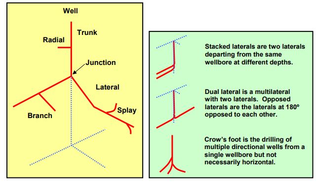
Multilaterals can also be classified by the way the laterals are positioned. There are three configurations in Fig 1, but multilaterals are not limited to the three configurations. Stacked laterals are laterals departing from the main wellbore at two different depths and usually intersect two different reservoirs. A dual lateral is a multilateral with two laterals, usually in the same reservoir. If the azimuth of the laterals are 180º apart, they are often termed opposed laterals. A crow’s foot is the drilling of multiple directional wells from a single wellbore to drain different parts of the reservoir or different reservoirs.
Reasons For Drilling Multilateral Wells
There is really only one reason for drilling a multilateral: the return on investment (ROI) for the operator is more than the alternative. Multilaterals are more expensive to drill, so production rates have to be higher for a longer period of time to payout the difference. Generally, multilateral wells are more effective in low to moderate-permeability reservoirs. Retnanto and Economides10 showed that the cumulative production ratio for a low to moderate permeability reservoir was maintained for a longer period. In higher permeability reservoirs, production interference will occur between laterals at an earlier time reducing the effectiveness of the laterals. Additionally, production in the parent wellbore would be limited by tubing diameter for high permeability wells.
Multilaterals can also be used in compartmentalized reservoirs or reservoirs with varying heterogeneities. Multilaterals will contact more of the producing formation, increasing production and probably reserves. Again, multilaterals must generate a higher ROI than multiple wells. Additional costs associated with multilaterals will depend upon the complexity of the multilateral and the cost of individual vertical or horizontal wells (also check oil well drilling well cost per foot). If surface locations or slots (in the case of an offshore platform or subsea template) are unavailable, then the economics become much more acceptable.
Multilateral Drilling Wells Classification System
In a multilateral well, the wellbores are either cased (check also Types Of Casing In Drilling Oilfield Wells) or open hole. The multilaterals can, therefore, have numerous configurations based on whether the main wellbore and laterals are cased or left open hole. These configurations allow the installation of a variety of junctions in a well. This variety necessitated the development of a classification system for users to compare, differentiate and select the multilateral applicable for their respective requirements.
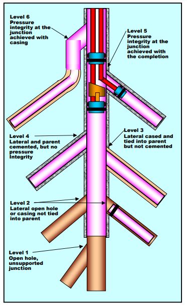
The TAML (Technology Advancement of Multilateral drilling wells) categorizes multilaterals based on the type of junction used. Figure 2 shows six types of junctions: Level 1 through Level 6. As the level increases, the complexity of the junction increases, and the cost and risks increase.
Level 1 Junction
A Level 1 junction has the main wellbore and the lateral left uncased at the junction, as shown in Figure 2. It is one of the simplest and least expensive multilateral and, hence, is one of the most common categories. Because of its simplicity, this type of junction can be placed in any hole size and any wellbore configuration. It can also be drilled by all directional service companies in oil and gas. However, a Level 1 junction has a few shortcomings. Since this is an open hole completion, it can only be used in a competent formation; otherwise, the borehole wall will collapse, or sand produced from the formation will fill up the wellbore. The open-hole laterals have limited reentry capabilities. There is no guarantee that any lateral can be reentered after pulling above the junction. There is no isolation of the laterals, and production must be commingled.
Several Austin Chalk wells are constructed as opposed to laterals. After drilling the first lateral, the motor assembly is brought up to the top of the build curve. The motor is oriented in the opposite direction. An open hole sidetrack is accomplished by time drilling. Depending upon the hardness of the formation, time drilling can take a few hours. Time drilling at a slow rate allows the bit to cut into the wall of the hole. Once enough of a ledge is generated below the bit, weight can be added to the bit to drill ahead.
Branches and splays can also be drilled off the wellbore’s horizontal portion. The parent horizontal wellbore is drilled first, and a dogleg is placed where the well will be sidetracked. If a multilateral is to go to the left of the parent wellbore, the parent wellbore will have a right-hand curve at the proposed junction. This makes it easier to make an open-hole sidetrack.
If a tripping pipe or a trip is required before the second lateral is finished, entry back into the second lateral is not guaranteed. Before getting to the junction on the trip in the hole, the toolface of the motor should be oriented in the direction of the desired lateral. Hopefully, the drill string will go into the intended lateral. Survey data from the MWD will indicate which lateral the drill string has entered
Level 2 Junction
In a Level 2 junction, the main wellbore is typically cased and cemented, while the lateral, or at least the junction, is left uncased (see Figure 2). This type of junction is the second most popular multilateral wells system used today since they can be drilled from an existing vertical well. In an existing well, it is typically drilled using a drilling whipstock to sidetrack out of the existing casing. Most service companies offer a retrievable whipstock to sidetrack out of the existing casing. The whipstock should be placed in the body of the casing to prevent milling a connection (check also: Milling In Drilling Operations).
On a new well, the sidetracks can be accomplished with pre-milled window joints. However, the pre-milled windows are much more expensive, more difficult to install, and in some cases, they require drilling a larger hole to accommodate a pre-milled joint. A casing liner can be dropped off outside the window to case the lateral if desired, but the liner does not connect back into the casing of the parent well. There are other shortcomings of a Level 2 junction. This junction allows limited reentry capabilities. The laterals, being open-hole, must be located in consolidated formations. Also, the laterals are not isolated.
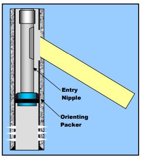
Reentry is likely but not guaranteed unless some selective completion equipment is used. If an orienting packer or liner hanger is placed below the window, an entry nipple can be oriented and placed opposite the window as illustrated in Figure 3. With this system, thru-tubing reentry is possible. During production, the production is commingled, and any tools or coiled tubing run in the hole will proceed through the packer. If entry into the upper lateral is desirable, a deflector is placed in the entry nipple with wireline or coiled tubing. Anything runs in the hole will then be deflected into the upper lateral. Additionally, production from the main wellbore can be isolated by setting a plug in the packer. Production from the lateral can be stopped by placing a sleeve into the entry nipple.
Level 3 Junction
The main wellbore in a Level 3 junction of multilateral drilling wells technology is cased and cemented, while the laterals are not cemented but cased only, as shown in Figure 2. The Level 3 junction has mechanical integrity at the junction but has no hydraulic isolation. This type of junction is created by mechanically tying the lateral to the main wellbore or installing casing strings in both the laterals and the main wellbore. The level 3 junctions are installed where the formations are not competent at the junction and where water or gas production into the junction is not problematic. There are a few shortcomings of the Level 3 junction. It may or may not have access to both the lateral and the main wellbore. Selective reentry may or may not be possible. The level 3 junction can be substantially more expensive depending on how it is accomplished.
Figure 4 (a) shows a relatively inexpensive Level 3 junction. A liner was run in the upper lateral and hung inside the parent wellbore. Flow from the lower lateral is around the upper liner or through slots in the liner that extend into the parent wellbore. As a trade-off for cost, there is no access to the lower lateral, but it can be accomplished in an existing well.
Figure 4 (b) shows a more expensive lateral using Sperry Sun’s LTBS system. The pre-milled window joint is run as part of the casing string. The LTBS requires drilling a slightly larger hole for the casing since the window joint has a larger OD than the normal casing coupling. A latch coupling is placed below the window joint to check the orientation of the casing and to orient the whipstock. The window in the casing is oriented in the desired direction before the casing is cemented
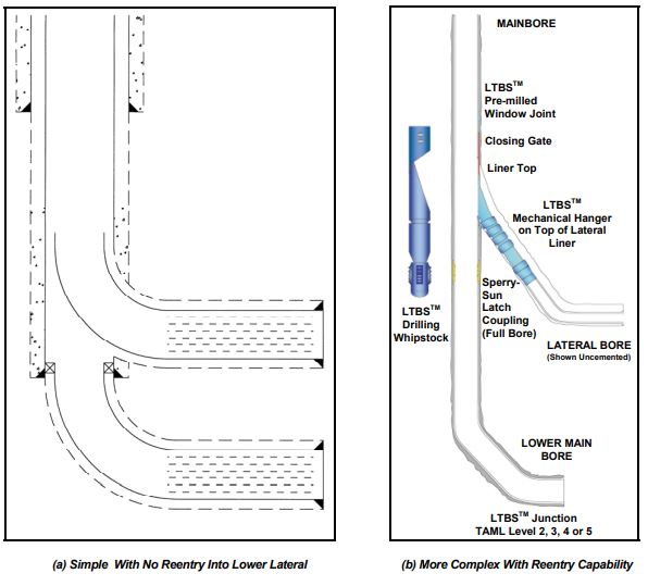
After completing the lower main bore, a whipstock is placed in the latch coupling, and the upper lateral is drilled through the window joint. After the drilling process, a liner is run in the hole. The liner is hung in the pre-milled window joint and locked in place without restricting the inside diameter of the casing. Then, the whipstock is removed. Access to both laterals is a virtual certainty. A diverter whipstock is placed in the latch coupling whenever full-bore access to the upper lateral is required. The diverter whipstock is removed from the latch coupling when the workover is complete. Production can be commingled or separated with packers and tubing.
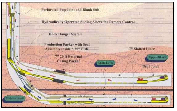
Other drilling systems are available for Level 3 multilateral wells, such as the Baker Oil Tools Hook Hanger system. The pre-milled window joint is required with this system. After completing the main bore, the well is sidetracked with a retrievable whipstock, and the upper lateral is drilled. A liner is run with the Hook Hanger system that hangs on the casing window. The figure illustrates that a main bore exit window can be installed in the liner to allow access to the lower lateral. It is all a matter of cost and the requirements of the well.
Level 4 Junction
A drilling multilateral wells Level 4 junction has both the main wellbore and the laterals cased and cemented, as shown in Figure 2. This type of junction involves running a whipstock, drilling a lateral, and running and cementing a liner in the lateral. Then, there are at least three options to install. One option is to wash over the liner top from the main wellbore, recover the liner and the whipstock, and return the main wellbore to full ID (Sperry Sun RMLS and Baker Root System). The second option is to mill a hole through the lateral liner and hollow whipstock. This option results in the loss of one hole size in the main wellbore but is usually the same size as the second lateral. The third option is to run a hollow whipstock and then, perforate the casing and the hollow whipstock. However, this option results in no access to the lower laterals.
The level 4 junction has mechanical integrity but is assumed to have no pressure integrity. Cement cannot always provide pressure integrity. Another advantage of this junction is that reentry is possible in most cases through the main bore or the tubing.
Level 5 Junction
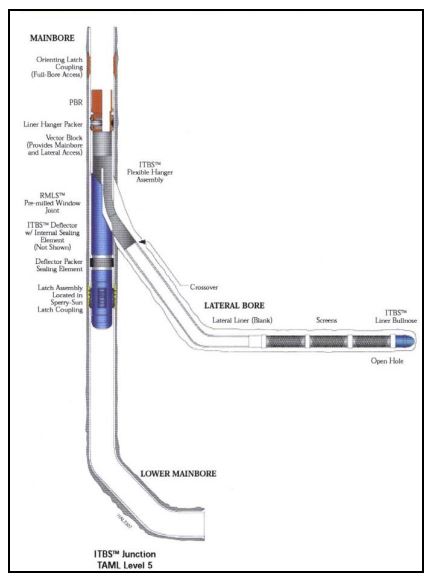
A Level 5 junction builds upon the Level 4 system by providing pressure integrity at the junction. The pressure integrity is achieved in the completion by running tubing and isolation packers, as illustrated in Figure 2. However, the pressure integrity is lost if a problem develops in the tubular above the packer. This type of junction allows access to both wellbores, usually through tubing. Another system uses a diverter packer assembly. The liner is run and diverted into the lateral. When the liner reaches the target depth, it stings into the diverter assembly, as shown in Figure 6. The level 5 junction, however, has a few disadvantages. It is much more expensive and is more risky to run. The more complex a system, the more likely there will be a mechanical failure during the installation.
Level 6 Junction
Level 6 junction is one in which full pressure integrity is achieved with the main casing string. There are two types of level 6 junctions: expandable metal junctions and splitter. They are used in new installations only because the expandable metal junction or splitter must be run as part of the casing string. The expandable metal junction requires under-reaming the hole where the junction will be placed to expand the junction before setting cement. The splitter junction requires drilling a much larger diameter hole from the surface down to run the splitter. For this reason, splitters are usually run at shallower depths.
References
- Karlsson, H. and Bitto, R.; “Worldwide Experience Shows Horizontal Well Success,” World Oil, March 1989, pp 51-56.
- Lang, W. J. and Jett, M. B.; “High Expectations for Horizontal Drilling Becoming Reality,” Oil and Gas Journal, Sept 24, 1990, 70-79.
- Moore, P.L.; Drilling Practices Manual, Petroleum Publishing Co., Tulsa, 1974, Chapter 8.
- Walker, R.E. and Mayes, T.M.; “Design of Muds for Carrying Capacity,” Journal of Petroleum
Technology, July 1975, pp. 893-900. - Chien, S.F.; “Annular Velocity of Rotary Drilling Operations,” Journal of Rock Mechanics, Min. Science, 1972, 9, pp.403-416.
- Tomren, P.H., Iyoho, A.W., and Azar, J.J.; “Experimental Study of Cuttings Transport in Directional Wells,” SPE Drilling Engineering, Feb 1986, pp. 43-56.
- Zamora, M. and Hanson, P.; “Rules of Thumb to Improve High-Angle Hole Cleaning,” Petroleum Engineer International, two-part series, Jan 1991, pp. 44-51 and Feb 1991, pp. 22-27
- Saasen, A., Marken, C., Sterri, N. and Jakobsen, J.; “Monitoring of Barite Sag Important in Deviated Drilling,” Oil and Gas Journal, Aug. 26, 1991, pp. 43-50.
- Chambers, M.R.; “Multilateral Drilling Wells Technology Gains Broader Acceptance,” Oil and Gas Journal, November 23, 1998, 47-52.
- Retnanto, A. and Economides, M.J.; “Performance of Multiple Horizontal Well Laterals in Low to Medium Permeability Reservoirs,” SPERE, May 1996, 73-77
- Chambers, M.R.; “Junction Design Based on Operational Requirements,” Oil and Gas Journal, December 7, 1998, 73-84.
- Rump, P., Bairagi, R., Fraser, J. and Mueller, K.; “Multilateral / Intelligent Wells Improve Development of Heavy Oil Field – A Case History,” IADC/SPE Drilling Conference, 2004.