Pulling production tubing means recovering the production string from an existing well. The packer may come out with it, remain set while the tubing seals are withdrawn, or require a separate retrieval operation. The result depends on the installed tubing-to-packer connection, the packer’s recovery design and the condition of the equipment. [1, 2]
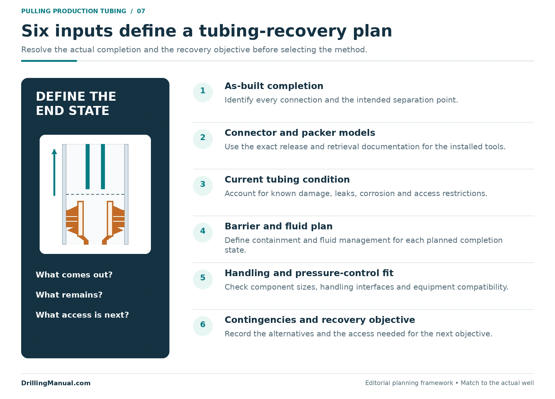
Start with the repair objective and the actual completion drawing. “Pull the tubing” describes a surface activity; it does not identify every component that must be recovered or the access that will remain afterward. This guide explains how to define that scope before selecting equipment and writing the well-specific program.
Why Is Production Tubing Pulled?
Possible reasons include replacing damaged or leaking tubing, recovering an integral completion component, changing tubing size, changing an artificial-lift installation, or gaining access for a different completion. Deposits or equipment failures can also justify recovery when a suitable repair cannot be performed through the installed string. The fault and the access requirement must both be established. [1]
For example, replacing a removable valve insert is different from replacing the body into which that insert lands. Some work can be performed through the tubing; other work requires recovery of the string itself. The broader workover operations guide discusses that access decision.
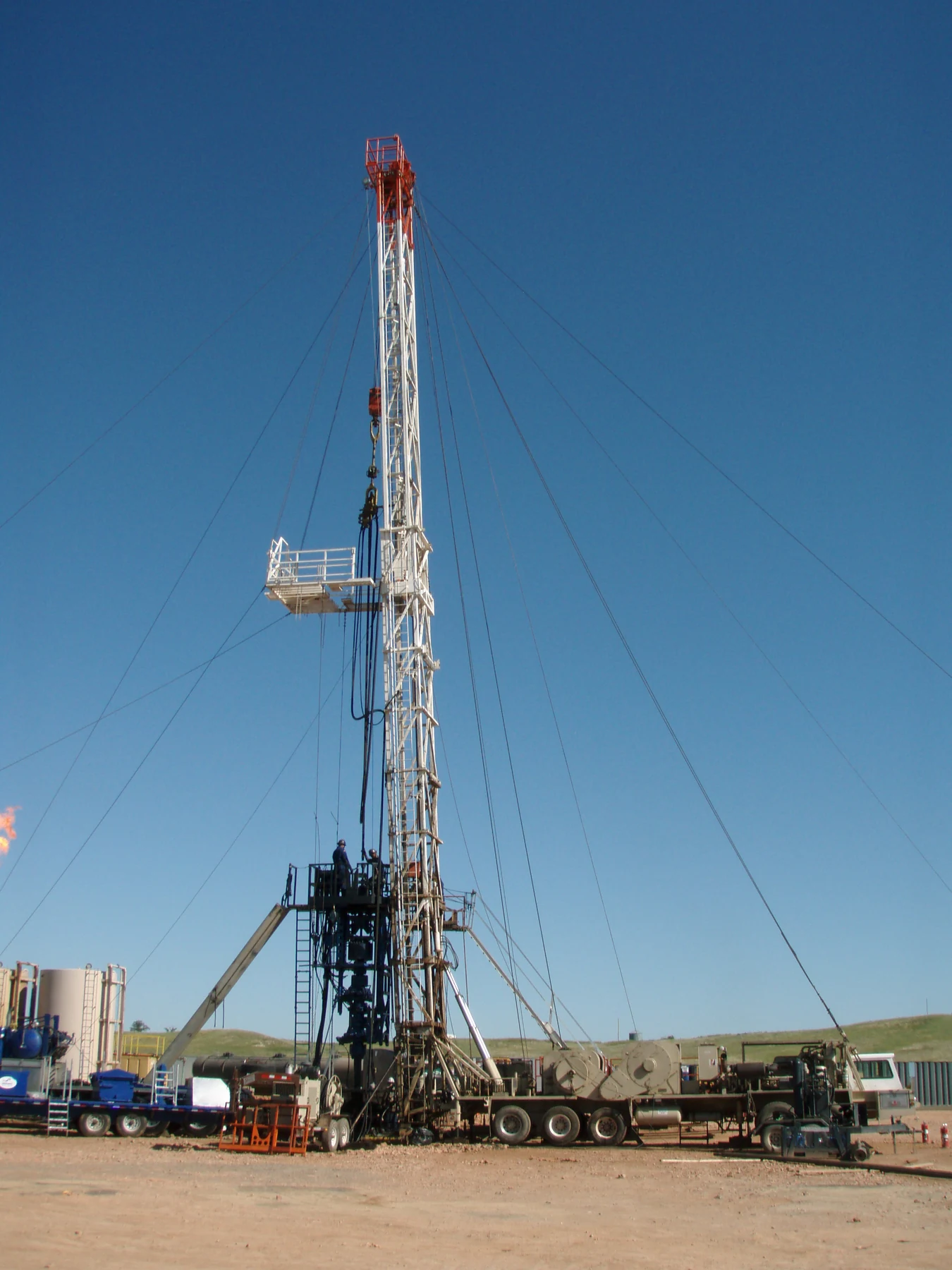
Photo: Joshua Doubek / Wikimedia Commons, CC BY-SA 3.0. Resized and converted from JPEG to WebP; no crop or content alteration.

Does the Packer Come Out With the Tubing?
There are three useful recovery arrangements to distinguish. They are examples of completion architecture, rather than universal release sequences. In each case, the intended result still depends on the installed equipment, its condition and successful execution of its specified release method. [1, 2]
1. Tubing Connected to a Retrievable Packer
Where the packer is an integral part of the production string, the tubing can provide the connection through which the packer is released and recovered. The released packer and any tailpipe still attached to it can then form part of the recovered assembly. However, the word “retrievable” does not specify the required manipulation or prove that the existing string can transmit it. [2]
Petroleum Well Construction describes several retrieval arrangements, including tubing manipulation and a separate retrieving tool. It also points out that a completion cannot necessarily transmit rotation when a release design requires it. Identify the model and the complete load path before treating the packer as part of the tubing pull. The retrievable packer guide provides equipment background. [2]
2. Tubing and Seals Withdrawn From a Retained Packer
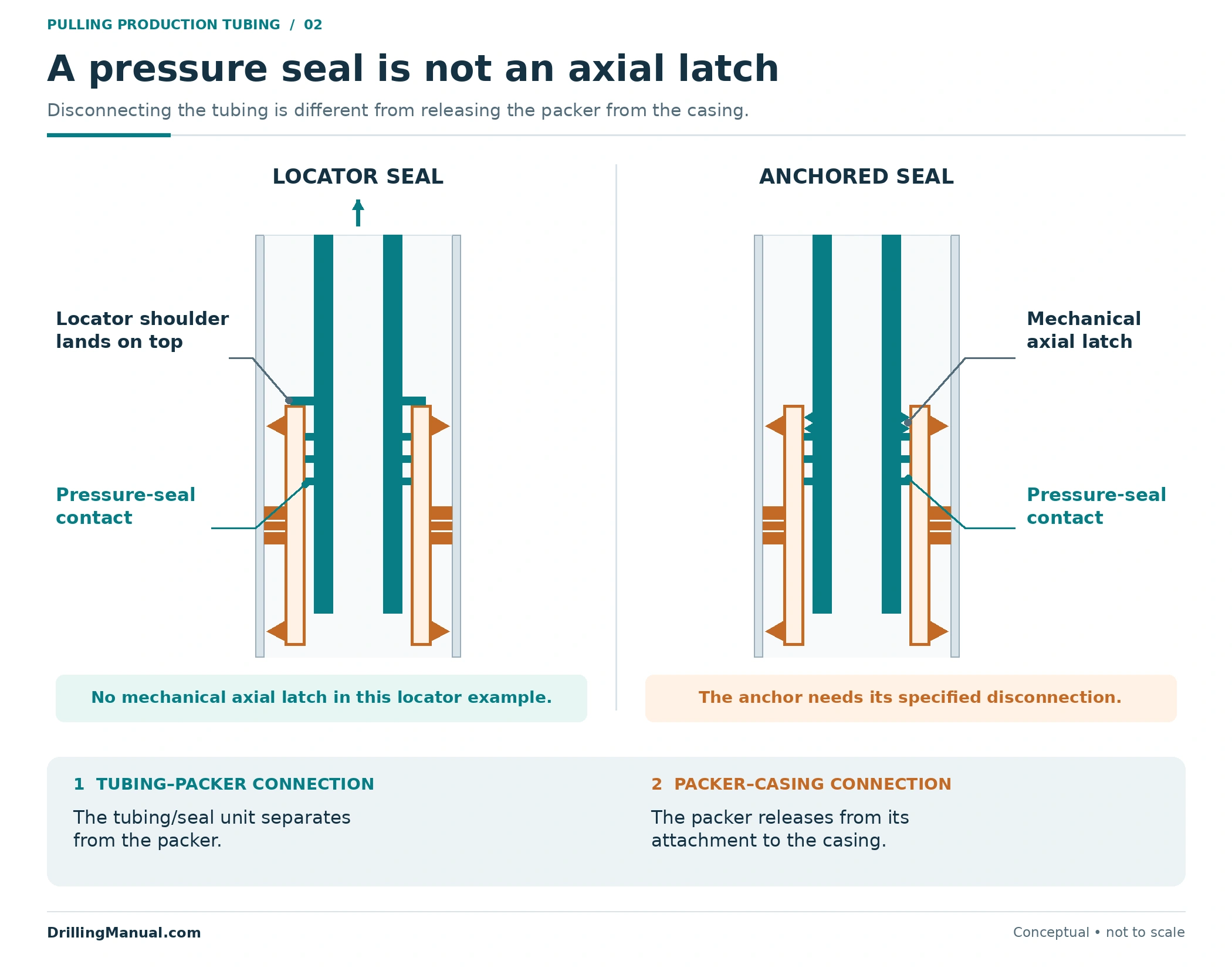
A production seal unit can connect the tubing to the bore of a packer that remains set in the casing. In a suitable arrangement, recovery separates the tubing and its seal unit from the retained packer. Equipment attached below that packer remains with the lower assembly. Recovering the tubing therefore does not, by itself, recover the packer or the tailpipe. [2]
The seal connection may be free to move or mechanically anchored. A seal-and-anchor arrangement needs its own disengagement method; it must not be treated as a plain sliding seal. Perrin makes this distinction explicitly when discussing removal of completion equipment. See the permanent packer and seal-assembly guide for the component terminology. [1, 2]
3. Tubing Removed Before a Separate Packer Retrieval
Some sealbore packers are retrievable with a dedicated retrieving tool. Their tubing and seals can be recovered as one scope, with packer recovery treated as another. This is why “retrievable packer” and “packer recovered on this tubing trip” are not interchangeable descriptions. The repair may require both scopes, or only the first. [2]
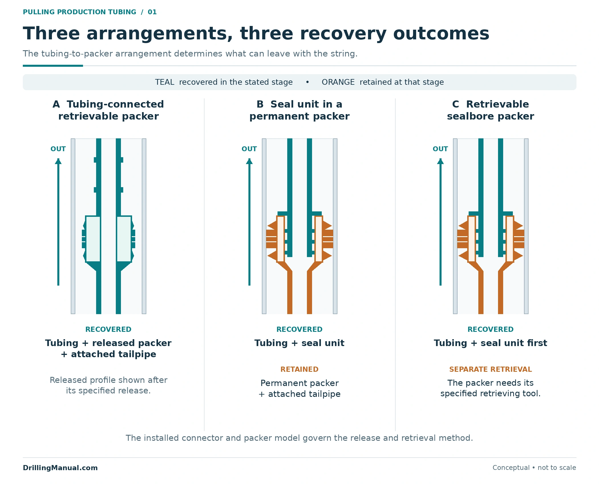
| Example arrangement | Recovered in the described scope | What may remain downhole |
|---|---|---|
| Integral tubing connection to a retrievable packer | Tubing, successfully released packer and still-attached lower components | Equipment outside that connected assembly |
| Removable tubing seal unit in a retained packer | Tubing and the seal unit after the specified disconnection | Packer, its attached tailpipe and lower equipment |
| Sealbore packer requiring a separate retrieving tool | Tubing and seals first, where the design permits | Packer until a separate successful recovery operation |
These outcomes assume an intact connection path and successful planned release. A parted string, damaged latch or stuck assembly changes the scope. [1, 2]
A Pressure Seal Is Different From an Axial Connection
Two questions explain much of the apparent confusion: what seals the pressure path, and what mechanically restrains the tubing? A stab-in seal stack forms a pressure seal inside its mating bore. An anchor or latch adds a mechanical connection. A locator shoulder can establish a landing position without providing the same axial restraint as an anchor. [2]
Consequently, withdrawing seals from a bore and releasing a packer from the casing are different events. A tubing connection can disengage while the packer remains set. Conversely, a tubing-connected packer may need its setting mechanism released before the combined assembly can be recovered. [1, 2]
A polished bore receptacle also requires the actual seal and restraint arrangement to be identified. The presence of a polished bore does not establish whether the installed seal assembly is free, latched or connected through another movement device. For the effects of restraint on the string, use the separate tubing movement calculations article. [2]
Which Components Come Out With Production Tubing?
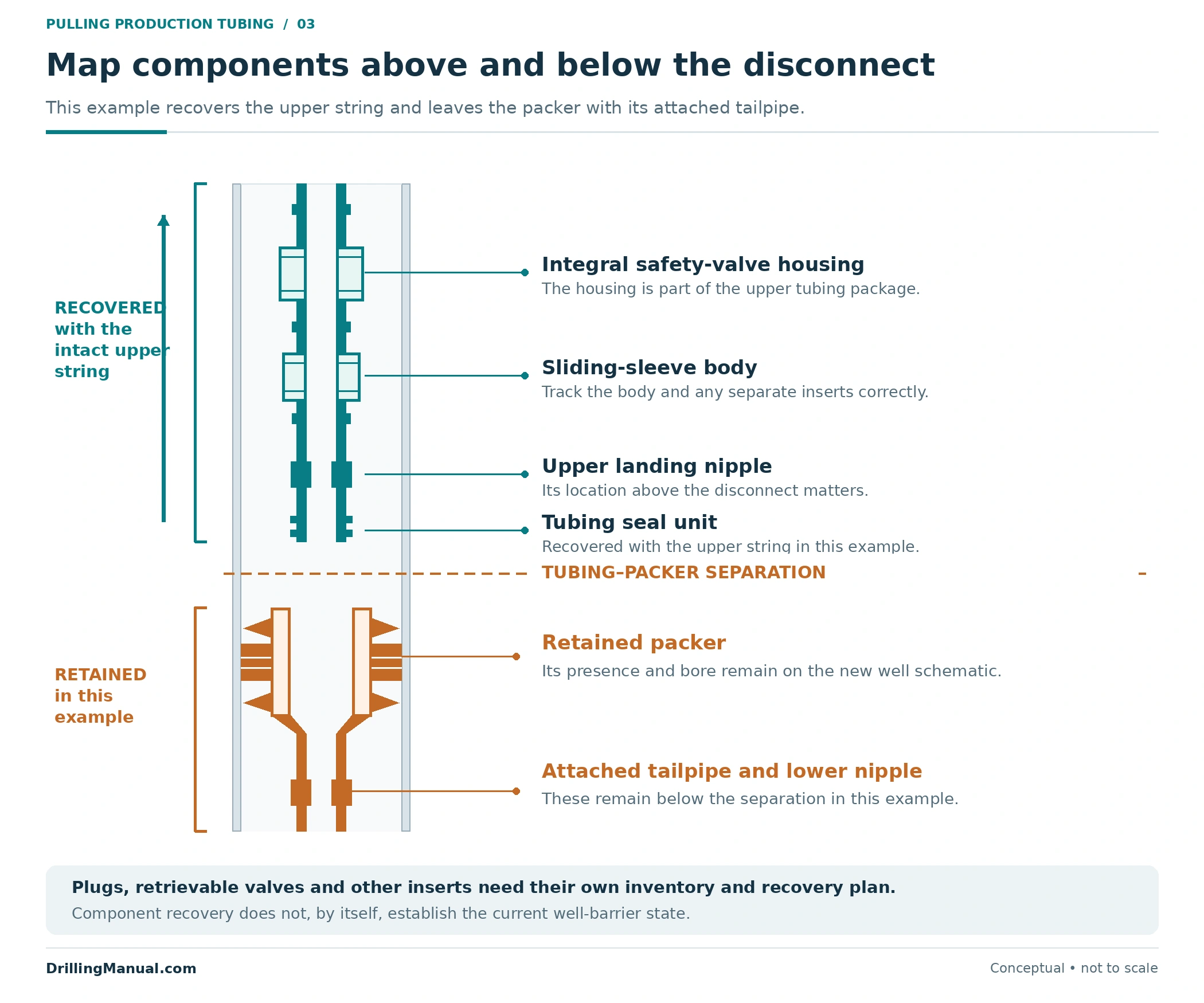
Trace the actual mechanical connections from the top of the string to the intended separation point. Then distinguish integral bodies from removable inserts. The following table is a planning aid assembled from the completion arrangements in the references; it does not replace the as-built equipment list. [1, 2]
| Component | Recovery implication | Evidence to check |
|---|---|---|
| Tubing joints, pup joints and integral nipples | Normally follow the intact string to which they are connected | Installed tally, connection locations and any planned disconnect |
| Tubing-retrievable safety-valve body | Its body is part of the tubing string | Exact valve arrangement and associated control system |
| Wireline-retrievable valve or plug | A separate insert; its retrieval can be independent of the tubing body | Installed position and whether it remains in place |
| Side-pocket gas-lift mandrel | The mandrel is in the string; its valve may be separately retrievable | Mandrel and valve types, rather than the label “gas lift” alone |
| Production seal unit | Can follow the tubing after the intended connection is disengaged | Seal bore, locator, anchor and movement-device arrangement |
| Packer | May follow the tubing, remain set or need another retrieval tool | Packer design and the planned recovery method |
| Tailpipe and lower nipples | Follow the assembly to which they remain attached | Connections below the packer and the actual separation point |
| Externally attached cable and protectors | Add a handling scope to the tubing-recovery task | Attachment arrangement, equipment size and recovery plan |
For a tubing-retrievable safety valve, distinguish recovery of the integral valve body from servicing a separate insert. Similarly, the gas-lift valve and mandrel arrangement determines whether a valve can be retrieved through the tubing or requires recovery of the string. [2]
A conventional ESP installation illustrates why an inventory cannot stop at the tubing bore. In the tubing-deployed arrangement shown in the reference, the pump and motor assembly are part of the connected recovery scope. The power cable is banded to the tubing, and the reference describes cable protection and a possible drain arrangement above the pump. The actual cable, attachments and drainage configuration therefore belong in the recovery review. This example does not describe every ESP deployment system. [2]
What Must Be Established Before Pulling Production Tubing?
Perrin identifies installed equipment, equipment condition, job objective and execution method as reasons why workover sequences vary. Preparation may include checking access, identifying deposited material, checking integrity and establishing how fluids can circulate. Turn those inputs into decisions, rather than treating a generic list of operations as a ready-made program. [1]
| Planning input | Decision it supports | Uncertainty it should resolve |
|---|---|---|
| Current schematic and installation tally | Define the intended separation point | What is actually connected above and below it? |
| Packer, seal and latch identification | Select the applicable release and retrieval method | Does tubing disconnection also recover the packer? |
| Tubing condition and intervention history | Assess the proposed load path and contingencies | Can the existing string transmit the required action? |
| Pressure, fluid and barrier information | Plan containment through each changed configuration | Which volumes and flow paths will be exposed? |
| Access, circulation and restrictions | Match tools and fluid paths to the actual completion | Can the intended tool or circulation route be used? |
| Recovery objective and acceptance evidence | Define when the tubing-recovery scope is complete | What must be at surface, and what can remain? |
The capability review includes hoisting, rotation, pumping, pressure control and tools suited to the tubular dimensions. Use the existing workover rig versus drilling rig comparison for unit selection and the pipe handling equipment guide for lifting and connection-handling functions. A hook rating alone does not establish that the complete recovery package is suitable. [1]
Why Packer Release or Seal Withdrawal Changes the Well
The completion separates fluid spaces as well as supporting equipment. Perrin cautions that hydrocarbons can remain below a packer after the main well-killing operation. Releasing the packer or separating the tubing seals from a retained packer can change communication with that lower volume. Circulation through one route must not be assumed to have displaced every isolated space. [1]
A retained packer has an outer seal against the casing and a bore through its body. The production seal unit provides another seal between the tubing and the mating bore. Removing that seal unit changes the configuration even if the packer’s outer sealing elements remain set. The retained packer alone does not close its central bore. Any installed isolation device and the actual flow paths must be assessed separately. [2]
Both the tubing bore and the annular spaces therefore belong in the pressure-control review. The applicable barriers, their verification and the handling of any trapped fluids must be specified for the actual well and the stage of recovery. The well integrity guide explains the broader barrier framework. [1]
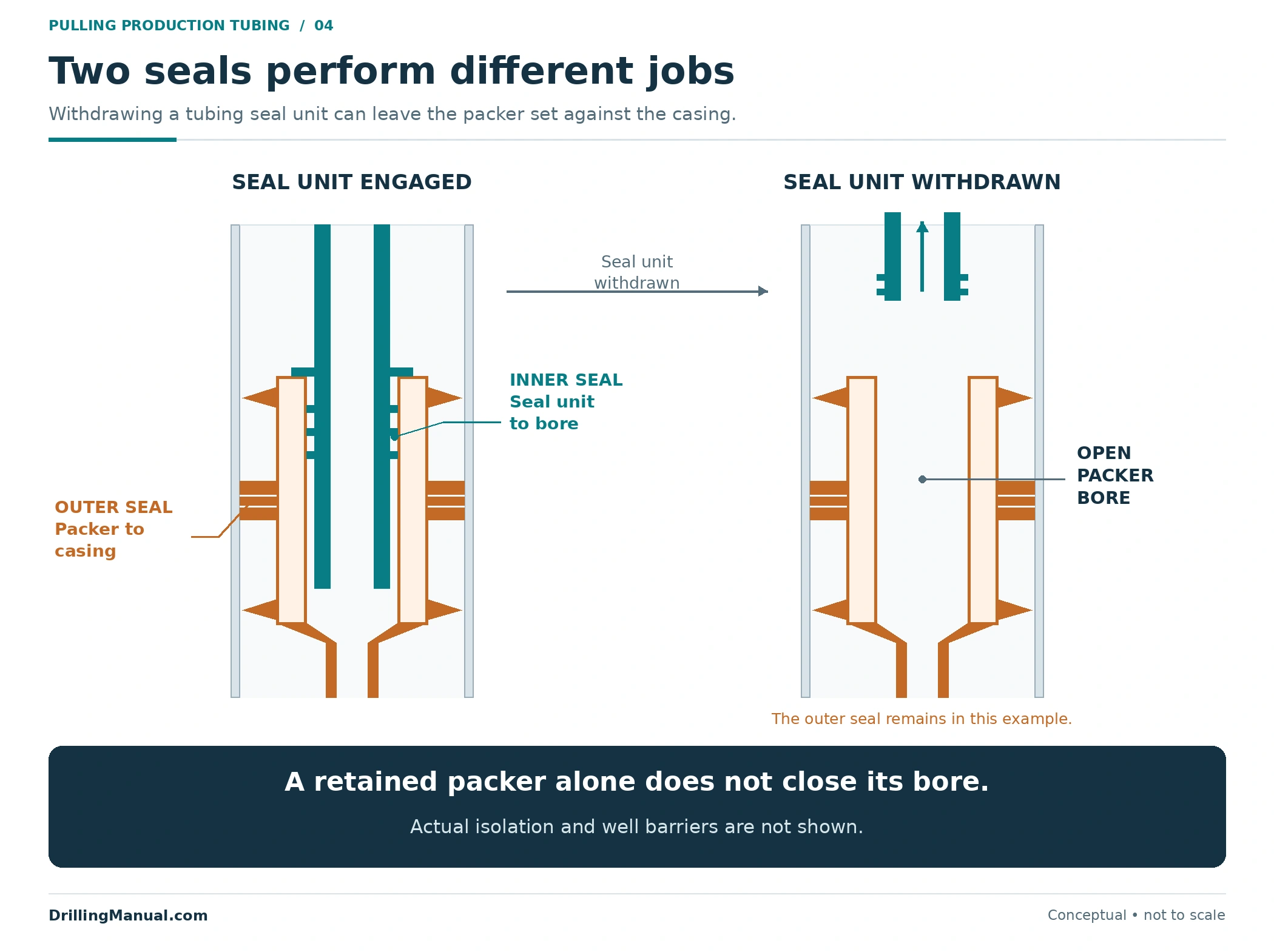
This is a planning explanation. Equipment-specific release actions, allowable loads, pressure limits and the operating sequence belong in the approved well program and the applicable equipment instructions.
Fluid Balance: An Illustrative Steel-Displacement Calculation
Removing tubulars changes the volume occupied in the well. Perrin discusses replacing displaced steel volume, avoiding swabbing and checking stability while pulling. That principle requires a correctly defined fluid-accounting case; one steel-volume calculation cannot describe every plugged, closed or fluid-retaining assembly. [1]
Consider an idealized length of uniform tubing that drains freely back into the well as it is recovered. Assume an outside diameter of 2.875 in., an inside diameter of 2.441 in. and a recovered length of 1,000 ft. These are illustrative dimensions, not a quoted tubing specification. Ignore couplings, accessories, losses, influx and any volume retained inside the recovered assembly.
Using the geometry of a hollow cylinder, the steel volume in oilfield barrels is:
Vsteel = (OD² − ID²) × L / 1029.4
Here, diameters are in inches and length is in feet. The conversion uses a 42-US-gallon barrel. Substituting the assumed dimensions gives (2.875² − 2.441²) × 1,000 / 1029.4 = 2.24 bbl, approximately 0.356 m³. This is an original geometry calculation illustrating the book’s steel-displacement concept.
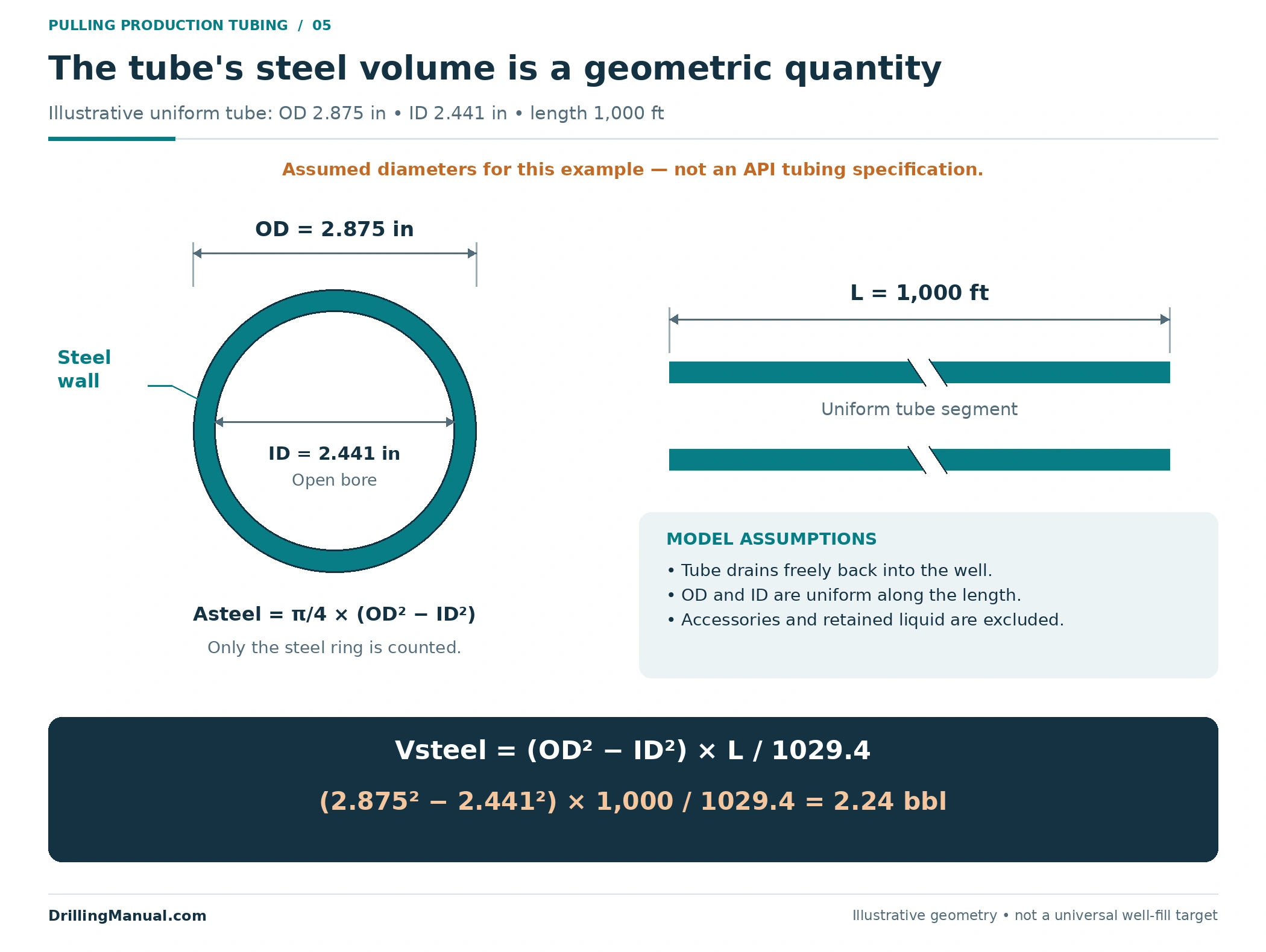
The result is a calculated steel volume for the stated case. It is not a universal fill target. If tubing retains liquid, a valve prevents drainage, or other components are being recovered, the accounting changes. The actual program must use the assembly’s dimensions and fluid condition, while observations of fill and returns are interpreted against the well’s expected behavior.
Likewise, a geometrically correct volume does not establish a permissible pulling speed. Swabbing is a separate pressure effect; Perrin specifically highlights it during recovery, particularly when removing a packer. [1]
Worked Planning Example: Two Wells, Different Recovery Scopes
The following hypothetical comparison applies the book-described arrangements. It is not a field case or a release procedure. Assume that both wells need the same upper tubing package replaced, that the installed connections are confirmed, and that the specified releases are achieved without leaving a fish. [1, 2]
Well A: the tubing is connected integrally to a retrievable packer, with a tailpipe attached below. The planned recovered inventory includes the upper tubing package, the released packer and the attached tailpipe.
Well B: the tubing terminates in a removable seal unit inside a permanent packer. The packer and tailpipe are intended to remain. The planned recovered inventory includes the upper tubing package and the seal unit, after its specified disconnection.
| Recovery check | Well A | Well B |
|---|---|---|
| Upper tubing package | Recovered | Recovered |
| Packer | Recovered after its designed release | Retained in the casing |
| Tailpipe attached to that packer | Recovered with the intact assembly | Retained with the packer |
| Important recovered interface | Released packer assembly and connected equipment | Seal unit and any relevant connection hardware |
| Access below the former tubing end | Assess the well after packer removal | Still limited by the retained packer and lower assembly |
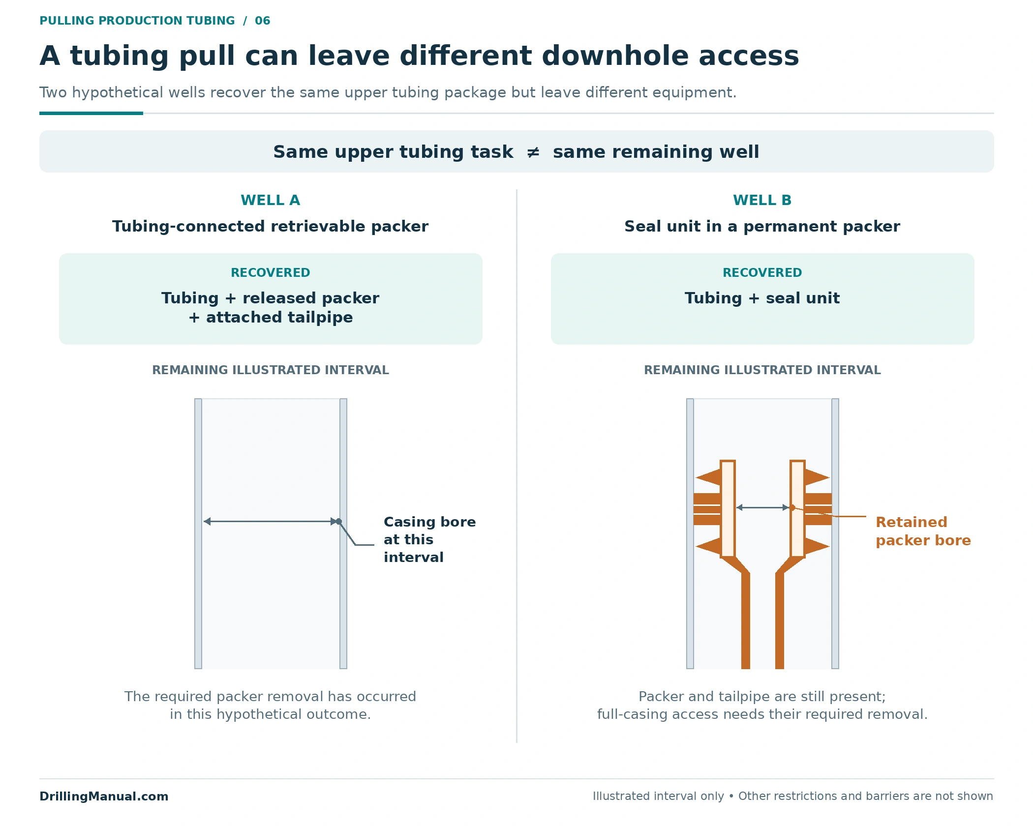
Suppose the next objective changes to a job requiring access larger than the retained packer bore. Well B now needs a further access decision: its completed tubing pull has not removed that restriction. Well A also requires an updated schematic and confirmation of remaining restrictions; recovery of its packer does not prove that the entire well is unobstructed.
The useful comparison is therefore the resulting well configuration. Joint count alone misses the different lower assemblies and any additional retrieval scope. The planned inventory and the actual recovered inventory should agree before the next operation relies on the assumed configuration.
What If the Tubing or Packer Will Not Release?
A recovery design describes what equipment is intended to do. Its condition determines whether that action remains feasible. Perrin specifically identifies questionable tubing condition as a reason to reconsider using the existing string to transmit packer-release forces. Petroleum Well Construction also distinguishes ordinary retrieval from separate packer-removal work. [1, 2]
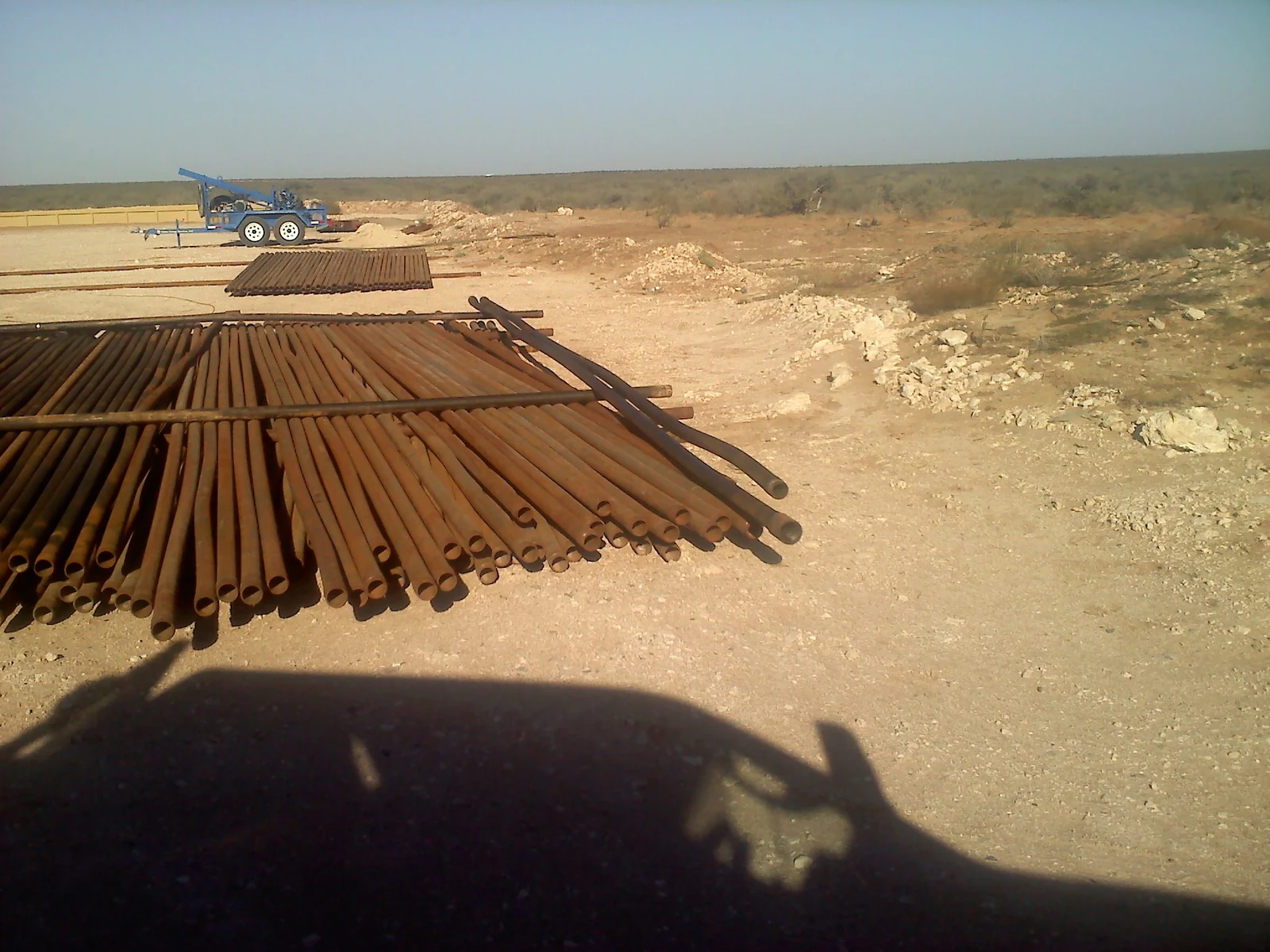
Photo: Schwindj / Wikimedia Commons, CC BY-SA 3.0. Resized and converted from JPEG to WebP; no crop or content alteration.

The response should follow the approved contingency and the evidence from the well. Reassess the identified connection, the existing tubing’s condition, the equipment load path and the need for a different retrieval approach. A larger available hookload does not restore strength to damaged tubing or establish that a latch has disengaged. [1]
Separate fishing or milling work can require a different toolstring, access and equipment capability. If the operation leaves part of the assembly downhole, the remaining inventory becomes part of the next work scope. Do not continue to describe the well using the original complete-string assumption. [1, 2]
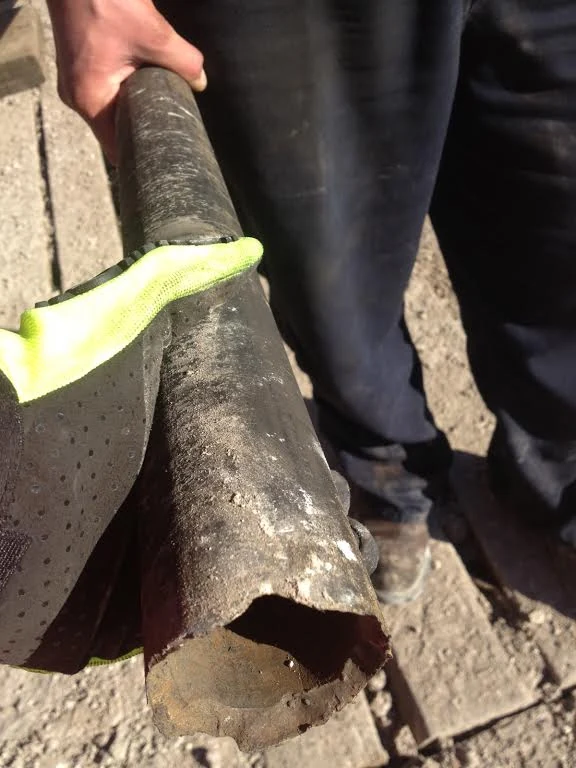
Photo: Schwindj / Wikimedia Commons, CC BY-SA 4.0. Converted from JPEG to WebP; no crop or content alteration.

How to Verify What Was Recovered
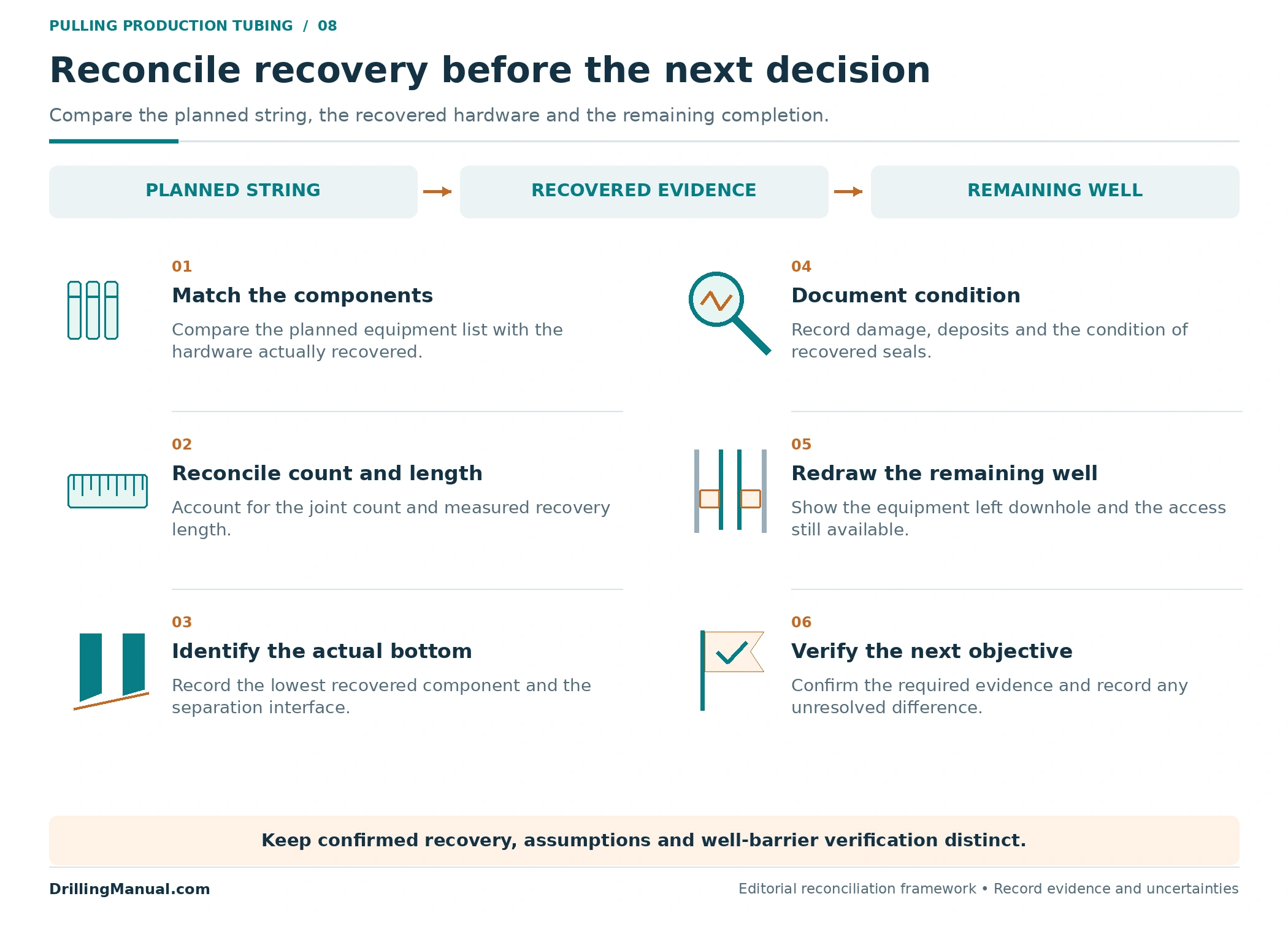
Use the intended separation point to organize the recovery record. The following is an editorial reconciliation method based on the references’ connection and condition distinctions. It helps turn “tubing out” into a description of the actual well left for the next operation.
- Compare the recovered tally with the installed tally. Reconcile lengths and components, including pup joints and equipment bodies.
- Identify the bottom of the recovered assembly. Establish whether it ends at the intended seal unit, disconnect, packer or another location.
- Record the observed condition. Describe damage, deposits and the condition of recovered connection and seal components without assuming that appearance alone proves the original failure mechanism.
- Account for what remains. Record retained packers, tailpipes, plugs or other equipment relevant to the next scope.
- Revise the completion drawing. Show the configuration and restrictions that subsequent tools and operations will actually encounter.
What Determines Pulling Time and Cost?
The number of joints is one input, but it does not define the whole job. The required release method, component condition, separate packer work and the equipment needed to complete the objective can change the scope. Perrin emphasizes that a unit’s daily rate alone does not establish the lowest overall job cost. [1]
A useful estimate therefore separates the planned tubing-recovery scope from identified contingencies and later operations. The example wells above can require similar upper-tubing handling while leaving different access work to be completed. A single “hours to pull tubing” figure would hide that distinction.
Frequently Asked Questions
Can Production Tubing Be Pulled Without Removing a Permanent Packer?
Yes, where the completion provides a suitable disconnect or removable seal connection. The tubing and seals can be recovered while the packer remains. An anchored connection needs its specified disengagement method; it must not be assumed to behave as an unlatched locator seal. [1, 2]
Does a Retrievable Packer Always Return on the Production Tubing?
No. Some arrangements permit recovery on the connected tubing, while a retrievable sealbore packer may require a separate retrieving tool. Identify the installed design and the intended sequence of recovery scopes. [2]
Is the Well Isolated Just Because the Packer Remains Set?
A set packer is not automatically a closed-bore plug. Its outer seal and the tubing-to-packer seal are different interfaces. The retained equipment, bore closures and applicable verified barriers must be assessed in the actual configuration. [1, 2]
What Is the Difference Between Pulling Tubing Wet and Dry?
The fluid-accounting distinction is whether the recovered tubing retains liquid or drains as intended. “Dry” does not mean that the well itself is empty. Verify valves, plugs and drainage arrangements before selecting the volume basis; the steel-only example above applies solely to its stated draining case. [1, 2]
How Much Overpull Should Be Applied to Release a Packer?
This article cannot supply one valid value. The installed release design, current string condition, complete load path and approved operating limits determine the permissible action. Perrin’s discussion of doubtful tubing condition is a reason to reassess the recovery approach, rather than add an arbitrary pull. [1]
Must Tubing Be Pulled to Replace Every Safety Valve?
No. A tubing-retrievable valve body is integral to the string, while a wireline-retrievable valve is a separate device installed within it. Identify the failed component and the actual completion arrangement before deciding that the production tubing must be recovered. [2]
Why Can Hydrocarbons Remain Below a Packer After Circulation?
The packer and completion can separate the lower volume from the route that was circulated. Packer release or seal withdrawal may change that communication. The program must therefore account for the actual flow paths and isolated fluids, rather than rely on circulation alone. [1]
When Is the Tubing-Recovery Scope Complete?
When the required recovery result has been demonstrated against the program: the intended components are accounted for, unexpected retained equipment is identified, and the revised well configuration is documented. A surface tally is part of that evidence; it does not by itself prove the condition or clearance of everything still downhole.
Technical References
[1] Perrin, Denis, with Michel Caron and Georges Gaillot. Well Completion and Servicing. Editions Technip, English edition, 1999. Chapter 5, especially printed pp. 255–257 and 293–296; physical PDF pp. 267–269 and 305–308 in the consulted copy. Used for workover objectives, preparation, equipment condition, completion removal, isolated fluids, swabbing and fluid balance.
[2] Economides, Michael J.; Watters, Larry T.; and Dunn-Norman, Shari, editors. Petroleum Well Construction. John Wiley & Sons; consulted digital copy. Chapter 11, especially digital PDF pp. 501–504, 511, 517–523, 525–526 and 543–545; Chapter 13, PDF pp. 608 and 628. Used for connections, retrieval arrangements, seal bores, completion components and the brief ESP/gas-lift examples. These page numbers refer to the 903-page digital copy, not the pagination of a printed edition.
The technical explanations above are based on these books. The completion examples, comparison tables, reconciliation method, geometric calculation and diagrams are original educational constructions. For separate occupational-safety reading, see the OSHA well-servicing overview. Photograph sources and licences are identified in their captions.