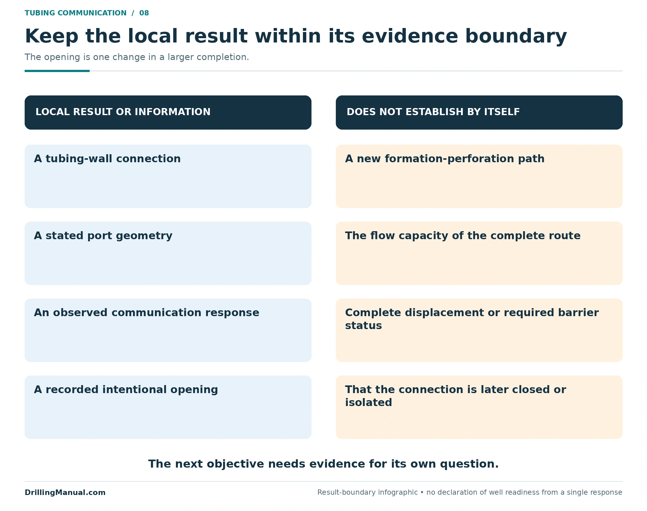
A tubing punch creates an intentional opening between the tubing bore and the space immediately outside the tubing. In a workover, that connection may be part of establishing a circulation route. It does not, on its own, show that fluid can travel through the complete intended circuit or that the well has reached the required condition. Perrin describes tubing perforators as communication devices; the well-intervention handout distinguishes a newly created opening from an installed sliding sleeve. [1, printed p. 274; PDF p. 286] [2, printed/PDF p. 102]
The most useful review starts with the two spaces being connected. Which annular compartment lies outside the target depth? What separates that compartment from the proposed return path? What evidence will establish the result needed for the next workover task? Answering those questions keeps the opening itself separate from circulation, displacement and barrier verification.
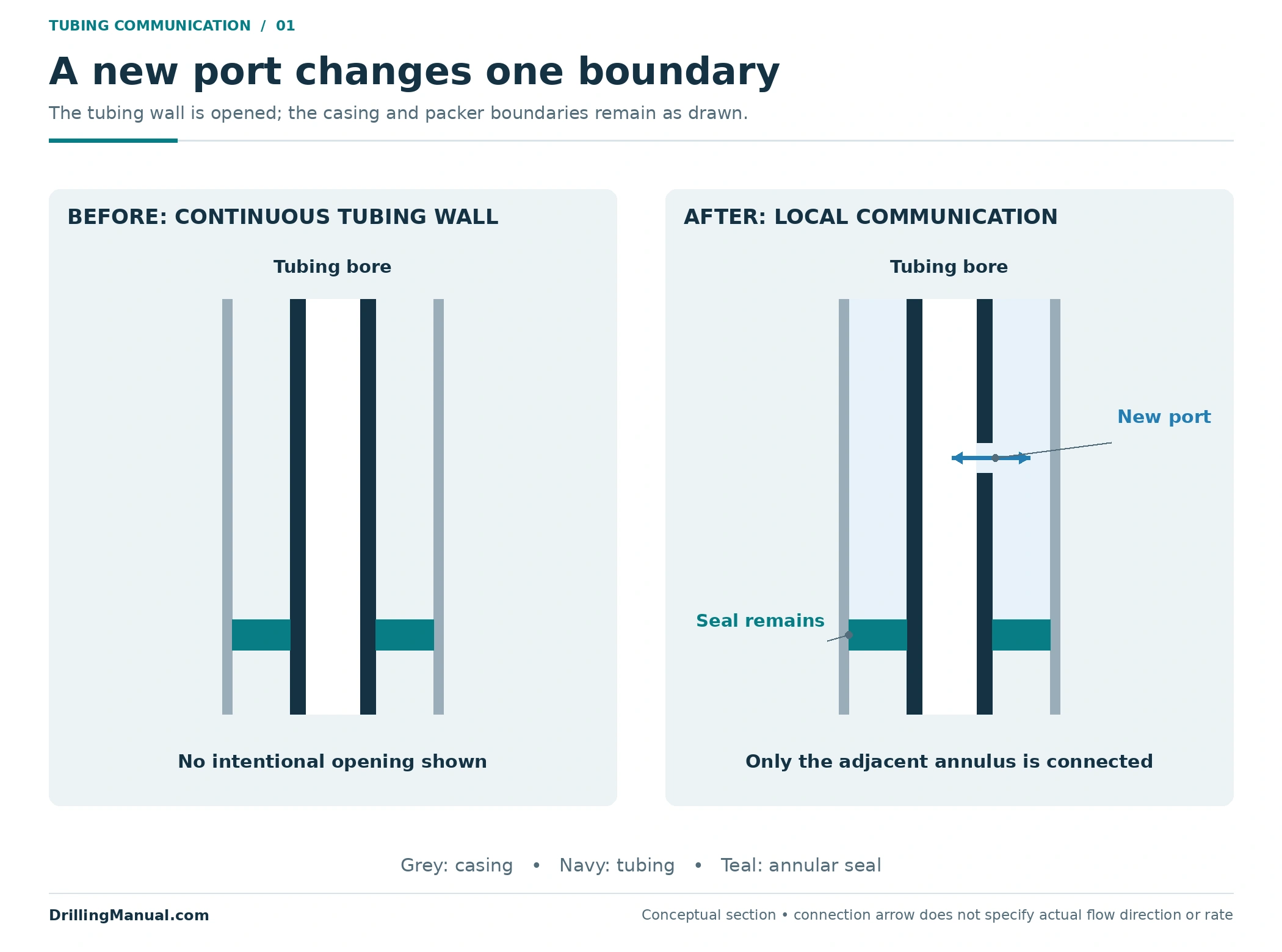
What does a tubing punch change?
It changes the tubing wall at a selected location so that the tubing bore can communicate with the adjacent annulus. Perrin places this application among downhole circulating devices and describes its use before a workover, as well as applications in a completion not originally equipped for a particular communication requirement. The purpose belongs to the completion as a whole; the physical change remains a local opening. [1, printed p. 274; PDF p. 286]
The source includes mechanical perforators and gun-type equipment. Those are different tool families, not alternative names for an identical mechanism. A generic explanation should not take the activation method or capability of one design and apply it to every tool. This article therefore addresses the connection being created, the completion geometry and the interpretation of the result. It does not describe firing arrangements, forces, tool assembly or a field sequence. [1, printed p. 274; PDF p. 286]
For a tubing punch review, a simple before-and-after drawing should leave every unaffected boundary unchanged. The tubing wall has a new opening; the casing wall has not thereby been perforated, a packer has not thereby been removed, and an existing valve has not thereby changed position. This is a conceptual drawing rule, but it prevents a common reasoning error: drawing the desired complete route as though the local operation had established all of it.
The broader workover operations guide explains where completion changes fit within an intervention. The narrower question here is how one intentional connection affects the interpretation of that completion.
Tubing punch geometry does not establish capacity
Perrin notes that some mechanical equipment can produce a calibrated opening. That is a feature of particular equipment, not a property to assume for every tubing punch. A stated port geometry describes one part of the connection. It does not describe the entire flow path through the completion or document the flow that the completed route has actually carried. Keep those statements separate in the review. [1, printed p. 274; PDF p. 286]
This is why a nominal opening description should retain its source. Was it an equipment specification, an intended result, or a documented condition? Each answers a different question. The distinction avoids using a planned opening as though its final condition had been observed, and avoids converting either description into an unsupported circulation-capacity claim. No generic port size or pressure requirement follows from this article’s conceptual drawings.

A tubing punch is different from shifting a sleeve
A sliding sleeve is an installed device with a designed communication arrangement. Opening it exposes its existing ports. The intervention handout describes sleeve-equipped completions and notes that an intentional tubing opening can be used where a sleeve has not been installed. The distinction is between operating a purpose-built device and creating a new connection through the tubing wall. [2, printed/PDF p. 102]
That distinction matters afterward. The presence of a hole does not provide the movement, sealing arrangement or selectable positions of a sleeve. Do not describe the new opening as a valve that can simply be shifted closed. Any later isolation of the connection is a separate equipment and verification question. The existing sliding sleeve guide owns the detailed explanation of sleeve construction and operation.
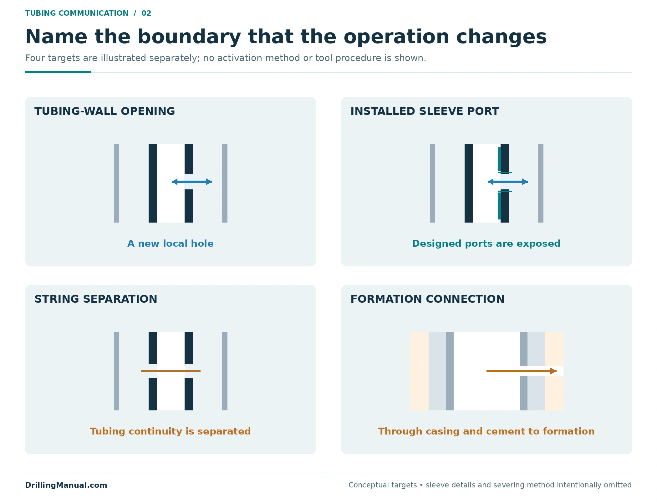
| Operation concept | Principal target | Intended local change | Do not infer |
|---|---|---|---|
| Intentional tubing opening | Tubing wall | Communication with the adjacent annulus | A complete surface circulation circuit |
| Sleeve opening | Installed sleeve and its ports | A designed device changes communication state | That every sleeve has the same positions or mechanism |
| String severing | Mechanical continuity of the string | A separation into distinct string sections | That making a local wall opening achieves this objective |
| Formation perforation | Casing, cement and the formation beyond | A wellbore-to-formation connection | That a tubing-to-annulus opening has reached the reservoir |
Keep the formation target separate
The perforating chapter in Petroleum Well Construction describes the formation connection through casing and cement. That target is outside the tubing-to-annulus relationship discussed here. A diagram can show both operations in one completion, but their openings must not be merged into a single symbol. The well perforation methods guide covers that larger subject. [4, Chapter 10 introduction, visible/PDF p. 452]
Similarly, “punch,” “cut” and “perforate” are inadequate job descriptions unless the intended boundary is named. State whether the objective is a local communication opening, axial separation of tubing, or a new formation connection. The operation title cannot replace that physical definition.
Locate the tubing punch within the actual completion
The annulus is not always one uninterrupted space. A packer separates the tubing/casing annulus on one side of its seal from the casing space on the other side. Multiple installed sealing elements can therefore make the phrase “opens into the annulus” incomplete. The target depth has to be related to the packer positions and other boundaries shown on the actual completion. [2, printed/PDF pp. 102–103]

In the illustrative two-packer arrangement, a wall opening above both packers connects to the upper annular compartment. An opening between them connects to the intermediate compartment. Neither local opening, by itself, creates a passage through a packer seal. The central tubing bore and the annular compartments must be traced separately. The sketch is a teaching construction, not a recommendation to place an opening at either location.
| Location in the illustrative completion | Immediate connection | Additional question |
|---|---|---|
| Above the upper packer | Tubing to the upper annular compartment | What is the actual route from that compartment to the intended return point? |
| Between two packers | Tubing to the intermediate annular compartment | Which existing paths, if any, connect that compartment elsewhere? |
| Below a packer | Tubing to the surrounding space below that seal | What is that space connected to in this particular completion? |
The well packer overview explains the sealing function. For this decision, the important information is the installed arrangement rather than the packer family alone. A proposed tubing punch location should be marked on a drawing that identifies the adjacent compartment explicitly. If the compartment is uncertain, the effect on the complete route is uncertain too.
Depth information needs a common reference. A target written against one datum cannot be compared reliably with a packer depth recorded against another without reconciling them. The ENI–Agip manual’s planning material includes completion drawings, dimensions and reference information. Its historical operational details are not reproduced here; the relevant lesson is to preserve the geometry and depth basis used for the review. [3, printed/PDF pp. 102–103]
A local connection is not a complete circulation route
A tubing punch can supply one missing connection, but a circuit also depends on the paths leading into and away from that connection. Consider the two original sketches below. Both have the same tubing-wall opening. In one, the proposed annular return path is interrupted above the opening. In the other, the drawn paths are continuous. The first cannot support the illustrated complete route; the second shows only that the simplified drawing contains a possible route.
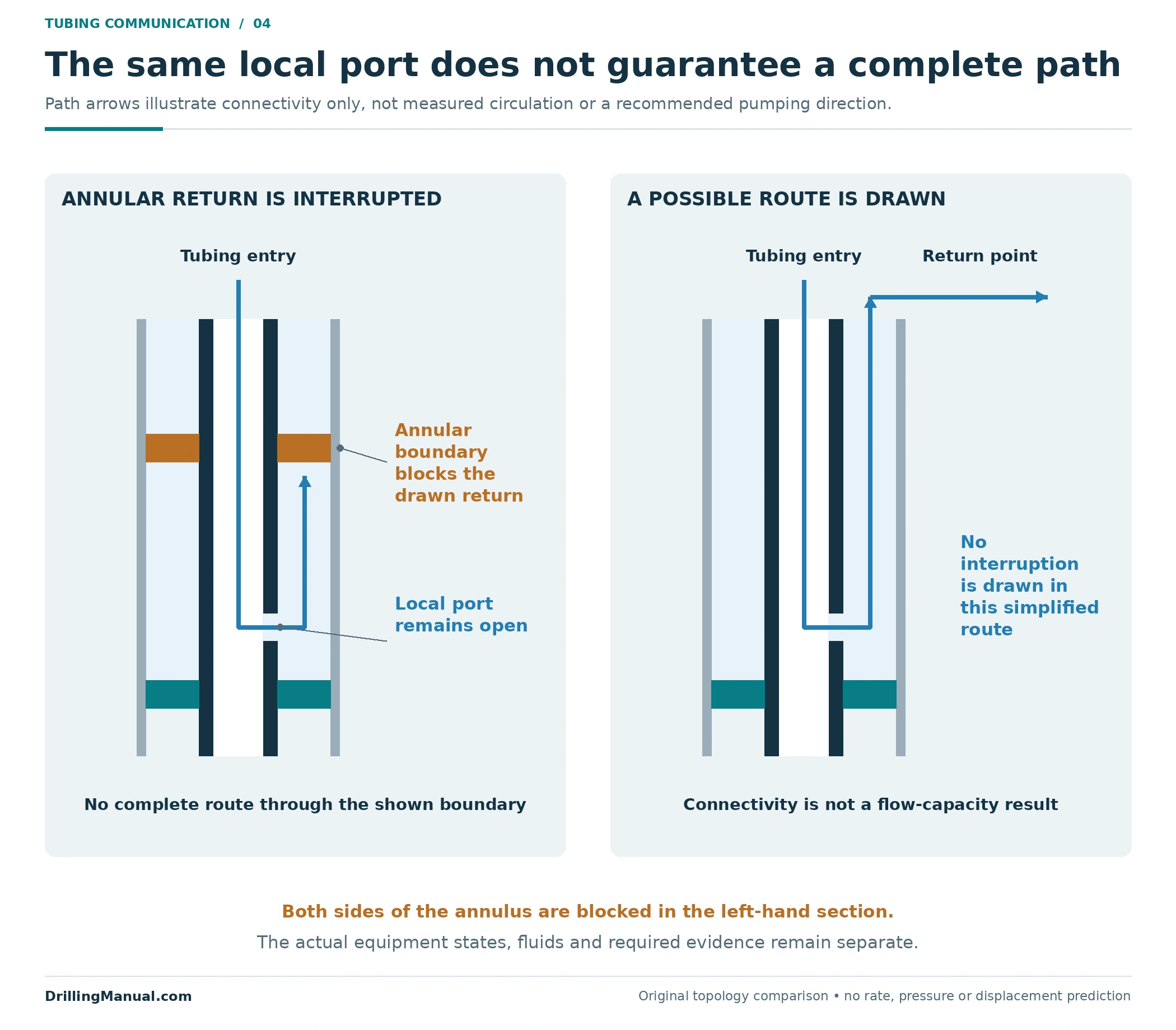
Neither sketch predicts a flow rate. It omits resistance, the actual fluids, pressure conditions and the detailed state of the completion. A continuous line on a diagram is a connectivity statement. Demonstrating the required circulation behavior is an additional evidence question. The handout’s separate descriptions of circulation devices, sleeves and packers provide the component basis for tracing those paths without treating all connections as equivalent. [2, printed/PDF pp. 101–103]
This distinction is useful when a workover report uses “communication established” as shorthand for a much larger objective. Ask what was actually observed and which part of the intended path that observation addresses. A connection at depth, a measured surface response and a documented circulation result are different pieces of information. Their labels should not be exchanged just because they occur in the same job.
The model also explains why an opening must be considered alongside existing devices. A circulation valve may have a direction-dependent function, and a sleeve has its own state. The handout describes different circulation devices; it does not justify drawing every device as an unrestricted two-way connection. Use the actual equipment function in the completion map. [2, printed/PDF pp. 101–102]
What does the observed response establish?
For a tubing punch, evidence should be matched to the intended result. A response interpreted as communication addresses whether two parts of the completion are connected under the observed conditions. It does not by itself describe the capacity of that connection, how completely a specified fluid has displaced another fluid, or the condition of every barrier. Those are separate claims requiring their own basis.

The ENI–Agip source calls for a record of tubing and annulus pressures and relevant well information. Keeping those records preserves the context of an observation. It does not turn an individual pressure reading into proof of all the outcomes expected from the intervention. The article’s evidence table is an original reasoning framework built around that distinction, not a set of test acceptance criteria. [3, printed/PDF pp. 102–103]
| Claim | Question the evidence must address | What the claim does not automatically establish |
|---|---|---|
| Communication | Are the specified spaces connected under the observed conditions? | Required circulation capacity or complete displacement |
| Circulation | Has the stated route carried the documented flow? | That every relevant volume has the required fluid condition |
| Displacement | Has the defined fluid-replacement objective been established? | Isolation of an opening or the integrity of unrelated barriers |
| Isolation or barrier verification | Does the required boundary meet its applicable verification? | That a different communication path has also been assessed |
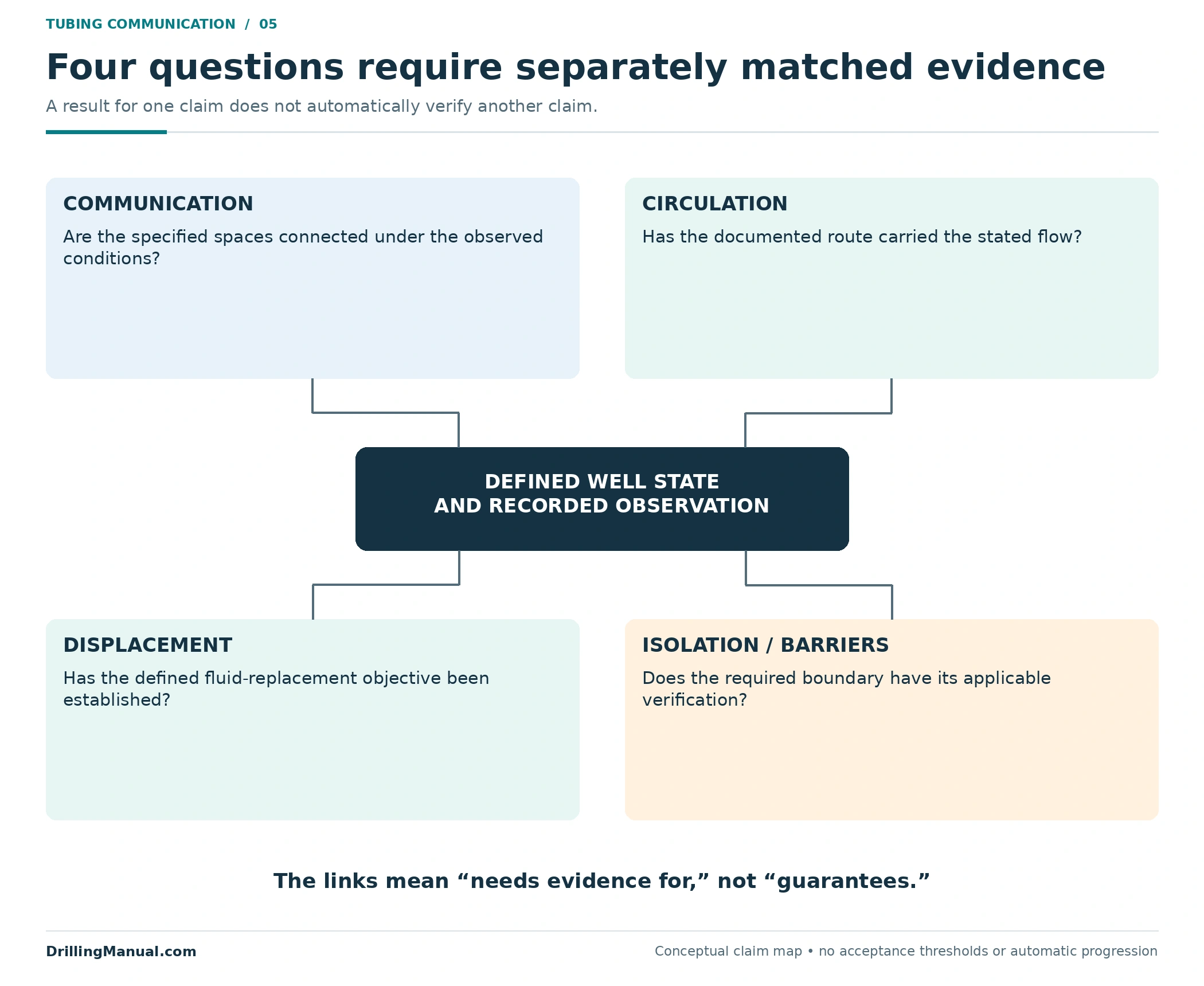
The distinctions are deliberately not shown as a ladder in which success at one level guarantees the next. A completion can have evidence for one question and unresolved uncertainty about another. Report the observed condition and the remaining uncertainty together. For the broader barrier framework, consult the well integrity guide; this article does not set a universal pressure threshold or declare a well safe from a single response.
Tubing punch planning needs both geometry and records
Tool access and the intended communication are different geometry questions. An assembly must be compatible with the passage and the applicable equipment at the target. The resulting opening must connect the intended spaces. Establishing one does not answer the other. The historical wireline manual addresses completion dimensions, equipment compatibility and the location of the operation; those inputs remain useful for explaining the distinction without reproducing its operating instructions. [3, printed/PDF pp. 102–103]
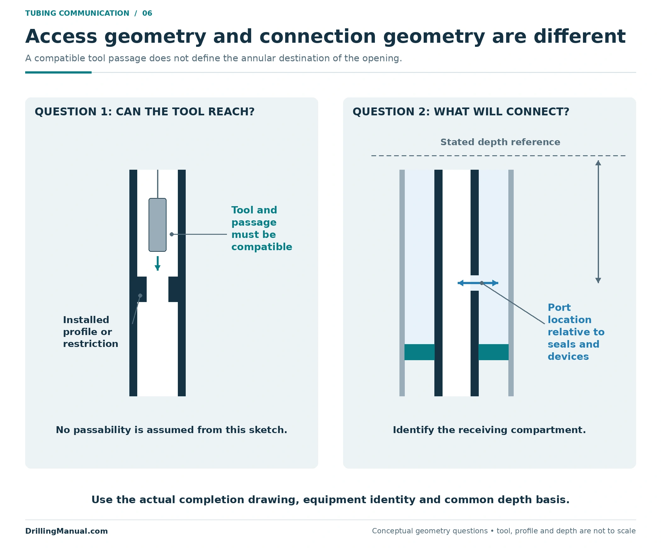
A landing nipple or lock profile is therefore relevant as an installed feature, not as proof that any selected assembly can be supported or located in it. The tool family and its compatible equipment must be identified. The absence of a familiar profile is likewise not resolved by relabelling a different completion feature. This discussion is about the information needed for a review, not a tool-selection recipe. [1, printed p. 274; PDF p. 286] [3, printed/PDF pp. 102–103]
Before assessing a tubing punch proposal, bring the drawing, depth reference, tubing information, known restrictions and existing communication devices into the same record. Preserve the stated well and fluid conditions alongside the intended opening. The ENI–Agip planning pages also refer to prior job information. A drawing reconstructed from memory is not equivalent to a completion record that identifies which features and dimensions have actually been confirmed. [3, printed/PDF pp. 102–103]
When records disagree, the disagreement is itself useful information. For example, a target described as above a packer in one document but between two packers in another has a communication ambiguity, not merely a drafting error. The purpose of reconciling the record is to establish which compartment the opening would enter. No assumed successful tool response can repair an undefined target on the drawing.
Record the changed completion, not only the operation name
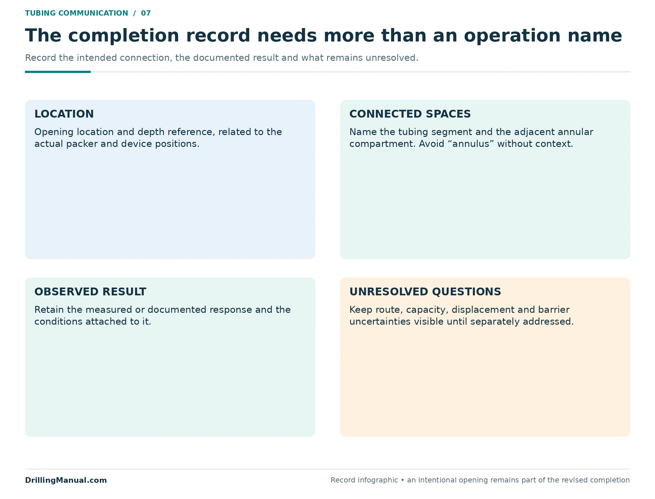
After a tubing punch operation, later interpretation needs to know that the connection was intentional. A future investigation of tubing–annulus communication should not begin with a drawing that still shows an uninterrupted tubing wall at that location. The updated record should identify the documented opening and distinguish its intended purpose from the evidence actually obtained.
| Record element | Why it matters to the next review |
|---|---|
| Location and depth reference | Places the opening relative to packers and other completion features |
| Connected spaces | Identifies the annular compartment rather than using “annulus” without qualification |
| Documented observation | Separates the actual response from the intended circulation or displacement result |
| Remaining uncertainty | Prevents an unresolved route, capacity or barrier question from becoming an assumed fact |
This record is also where the local result meets the next objective. If the next task requires a particular circulation route, record the evidence for that route. If it requires a particular isolation condition, retain that separate verification. The new connection should remain visible in both the completion drawing and the explanation of the well’s current state.
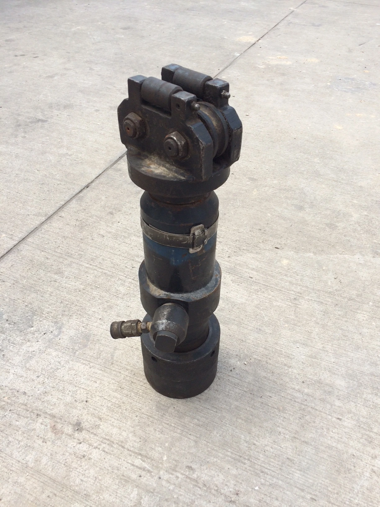

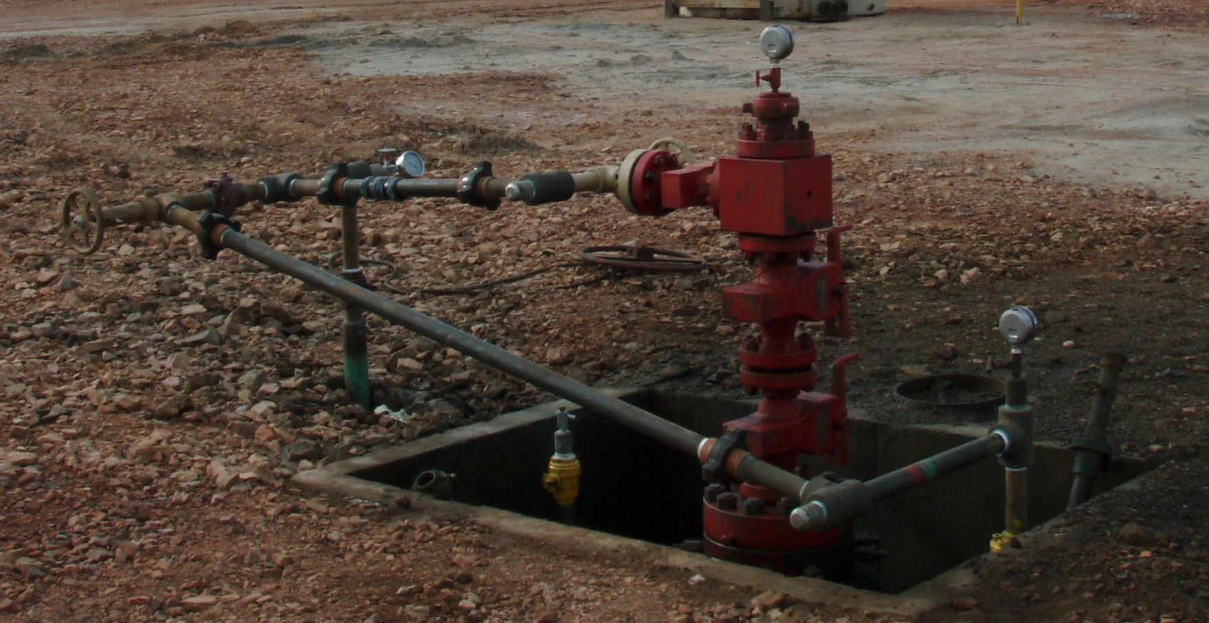
The surface pressure-control photograph provides equipment context only. It does not depict the downhole opening or demonstrate its condition. The same distinction applies to the wireline vehicle and gauge photographs: they illustrate the work environment and measurement context, while the original diagrams explain the hidden connections.
Frequently asked questions
What is a tubing punch used for?
It creates a deliberate tubing-to-annulus connection at a selected location. Perrin describes tubing perforators among communication devices used in servicing contexts. The purpose of the opening must be related to the actual completion; the local connection alone is not the complete workover result. [1, printed p. 274; PDF p. 286]
Does a tubing punch perforate the formation?
The intended target discussed here is the tubing wall. Formation perforation has a different target through casing and cement into the formation. These operations should be drawn and described separately so that an annular connection is not mistaken for a newly established reservoir connection. [1, printed p. 274; PDF p. 286] [4, visible/PDF p. 452]
Is making an opening the same as opening a sleeve?
No. A sleeve is installed equipment with a designed port and sealing arrangement. A new wall opening does not inherit that mechanism or its ability to change position. The handout identifies tubing perforation as a possible communication approach where a sleeve is absent, while treating the devices separately. [2, printed/PDF p. 102]
Does communication prove full circulation?
No. The local connection is only part of the route. The paths on both sides and the actual equipment states matter. Even a simplified tubing punch drawing with a continuous route establishes connectivity only; the required flow behavior needs evidence under the relevant conditions.
Why does position relative to the packer matter?
The packer divides annular spaces. An opening above its seal and an opening below it connect the tubing to different locations in the completion. With multiple packers, the intermediate compartment also has to be identified. A local tubing-wall opening does not itself bypass the packer seal. [2, printed/PDF pp. 102–103]
Can one pressure response prove the well is ready for the next task?
Not as a universal rule. The observation must be related to the specific question being tested. Communication, circulation, displacement and required barrier verification are distinct claims. Record the result that the evidence supports and preserve any unresolved condition relevant to the next operation.
Technical references
- Denis Perrin, in collaboration with Michel Caron and Georges Gaillot. Well Completion and Servicing. Éditions Technip, 1999. Printed p. 274, physical PDF p. 286: downhole communication devices and tubing perforators.
- Well Intervention Pressure Control, training handout, “Completion Equipment.” Printed and physical PDF pp. 101–103: circulation devices, sliding sleeves and packers. Undated handout; author not identified in the referenced copy.
- ENI S.p.A., Agip Division. General Wireline Procedures Manual, STAP-P-1-M-7110, Revision 0, issued 28 June 1999. The referenced copy has 318 PDF pages. Printed/PDF pp. 102–103: completion information, equipment context and reporting.
- James Barker and Phil Snider, “Perforating,” Chapter 10 in Petroleum Well Construction, edited by Michael J. Economides, Larry Watters and Shari Dunn-Norman. John Wiley & Sons. Chapter introduction, visible and physical PDF p. 452: the distinct casing–cement–formation target.