A steerable downhole drilling mud motors system allows directional changes (azimuth and/or inclination) of the well without tripping pipe to change the Bottom hole Assembly BHA, hence its name. This article is one of the Directional Drilling guide articles I recommend visiting to understand other deflection tool mechanisms.
It consists of a drill bit, a stabilized steerable PDM / Mud Motor, a stabilizer; and a directional surveying system that monitors and transmits to the surface the hole azimuth, inclination, and toolface (read also Surveying Calculations Methods) on a real-time basis.
The Major Components Of Steerable Downhole Mud Motors
There are five major components in a Steerable Drilling System. These components are:
- Drilling Bit
- Downhole Mud Motor
- Navigation Sub
- Navigation Stabilizers
- Survey System
Drill Bit
Steerable systems are compatible with different types of drilling bits: Roller cone Drill Bits or PDC Drill Bit. We usually use a PDC bit since this eliminates frequent trips to change the bit ( Read Also Bit Dull Grading Guide).
PDM
The motor section of the system causes the bit to rotate when circulating the mud through the string. This makes oriented drilling possible. The motors may also have the navigation sub and a bearing housing stabilizer attached to complete the navigation motor configuration.
Navigation Sub In Steerable Drilling Motors
The navigation sub (Drilling Subs) converts a standard Mud motor into a steerable motor by tilting the bit at a predetermined angle. The bit tilt angle and the sub’s location at a minimal distance from the bit allow both oriented and rotary drilling without excessive loads and wear on the bit and motor. The design of the navigation sub ensures applying the deflecting forces primarily to the bit face (rather than the gauge), thereby maximizing cutting efficiency.
Two types of subs are presently available for steerable downhole drilling mud motors:
- The double-tilted universal joint housing or DTU has two opposing tilts that reduce bit offset and side load forces, thereby maintaining an efficient cutting action.
- The tilted kick-off sub, or TKO, has two tilts in the same direction close to the bit.
The DTU and TKO both utilize double tilts to produce the bit tilt required for hole deflection in the steerable downhole drilling mud motor system.
Navigation Stabilizers
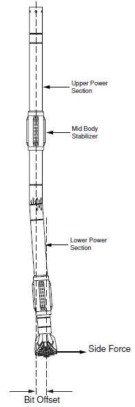
We use two specially designed stabilizers to operate the system and influence the directional performance of a steerable downhole drilling mud motor.
The steerable downhole mud motor stabilizer, or Upper Bearing Housing Stabilizer, UBHS, is an integral part of the navigation motor and is slightly under-gauge. The upper stabilizer, which defines the third tangency point, is also under-gauge and is similar to a string stabilizer.
The stabilizers’ size and spacing can also be varied to fine-tune assembly reactions in both the oriented and rotary modes.
Directional Drilling Survey System
It is essential to use a real-time downhole survey system to provide continuous directional information. Therefore, we use a measurement while drilling, MWD system. An MWD tool will produce fast, accurate data on the hole inclination, azimuth, and the navigation sub-tool face orientation. Sometimes, we use a wireline steering tool for this purpose.
Steerable Drilling Motors Mechanism
It is possible to change direction at will by placing the tilt angle close to the bit using a navigation sub on a standard PDM. We can use this tilt angle to drill in a specific direction, in the same way as the tilt angle will be generated by a bent sub with the drill bit being rotated by the mud motor when circulating.
However, since the tilt angle is much closer to the bit than a conventional bent subassembly, it produces a much lower bit offset. In other words, the driller can rotate the drill bit by rotating the entire string at the surface. (in the same way as when using a conventional assembly).
Hence, directional drillers can use the steerable drilling mud motor assembly to drill in a specific direction by
- Orienting the bent sub in the required direction and simply circulating the fluid to rotate the bit (as in the bent sub-assembly)
- Drilling in a straight line by rotating and circulating fluid through the drill string. When rotating from the surface, we will be circulating fluid also. Therefore, the rotation of the bit generated by the mud motor will be super-imposed on the rotation from the surface.
This does not alter the fact that the effect of the bit tilt angle will decrease with the rotation of the entire assembly.
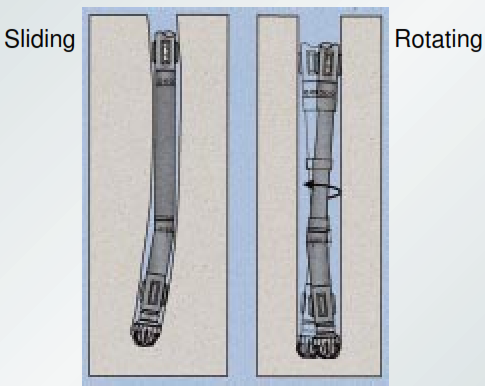
What is Sliding Drilling Mode?
When using the navigation sub and mud motor to drill a deviated section of the hole (such as build-up or drop-off of a hole section), we use the term “oriented or sliding drilling” to describe the drilling operation.
What is the Rotary Drilling Mode?
When drilling in a straight line, we use the term “rotary drilling” to describe the drilling operation by rotating the assembly.
How To Control Directional Work
The factors that affect the directional tendencies of the steerable downhole drilling mud motor system are as follows:
- Navigation sub-tilt angle
- Size of stabilizers
- Distance between the PDM stabilizer and the first stabilizer above the motor.
The Main Applications Of Steerable Drilling Mud Motor
The steerable Downhole Mud Motor systems are precious where:
- Changes in the direction of the borehole are challenging to achieve, where directional control is difficult to maintain in the tangent sections of the well. For example, formations with dipping beds where there may be a requirement for frequent changes.
- Another application uses steerable systems with MWD tools containing petrophysical and directional sensors. We call these MWD tools Logging While Drilling or LWD tools.
- The petrophysical sensors detect changes in the properties of the formations (lithology, resistivity, or porosity) whilst drilling. Therefore, we can determine if there is a requirement for a change in direction.
- Effectively, the steerable downhole mud motor assembly will track desirable formation properties and place the wellbore in the most desirable location from a reservoir engineering perspective.
Often, we use the term “Geosteering” when applying the steerable system to drill a directional well in this way.
Operation of a Steerable Downhole Drilling Mud Motor System
As described above, the steerable drilling mud motor system can drill directionally or straight ahead, as required. This enables the driller to control the well’s trajectory ( learn more about how Well trajectory calculations) without making time-consuming trips to change bottom hole assemblies.
Steering while Kickoffs
To steer the hole during kickoffs or course corrections, orient the system using MWD readings so the bit will drill in the direction of the navigation sub’s offset angle. When drilling in this way, the system is said to be drilling in the oriented or sliding drilling (since the drill string is not rotating) mode. As with conventional motor drilling, the downhole steering motor will drive the bit while locking the rotary table.
Controlling Dogleg With Steerable Downhole Mud Motor System
As mentioned, the system’s two stabilizers and bit serve as the tangency points defining the curve drilled by the oriented assembly. Control ling the dogleg rate by varying the placement and size of the stabilizers, using a DTU with a different offset angle, or by alternating drilling with oriented and rotary intervals.
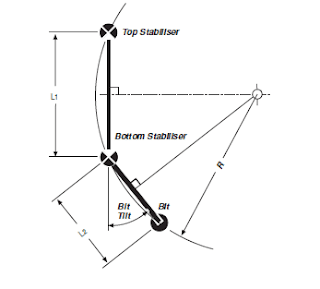
When oriented drilling, the theoretical geometric dogleg severity or TGDS produced by the system is defined by three points on a drilled arc. The three points required to establish the arc are:
- The Bit
- The PDM stabilizer or Upper Bearing Housing Stabilizer.
- The first stabilizer above the mud motor (upper stabilizer).
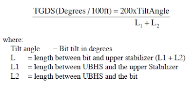
The radius of the arc is further determined by the tilt of the navigation sub, as seen in Figure: 2. The following essential relationship is produced by mathematical derivation.
Drilling Straight with a Steerable Downhole Mud Motor System
The system can also drill straight ahead by simple string rotation. The rotary table is typically turned at 50-80 RPM while the motor runs. When drilling this way, the system is drilling in the rotating mode.
Following The Directional Plan
Through careful well planning and bottom-hole assembly design, oriented sections are minimized, and the assembly is rotated as much as possible. This maximizes penetration rates while keeping well on course. Survey readings from an MWD tool enable efficient monitoring of directional data so the driller can maintain the well path close to the desired path. Slight deviations can be detected and corrected with minor oriented drilling intervals before they become significant problems.