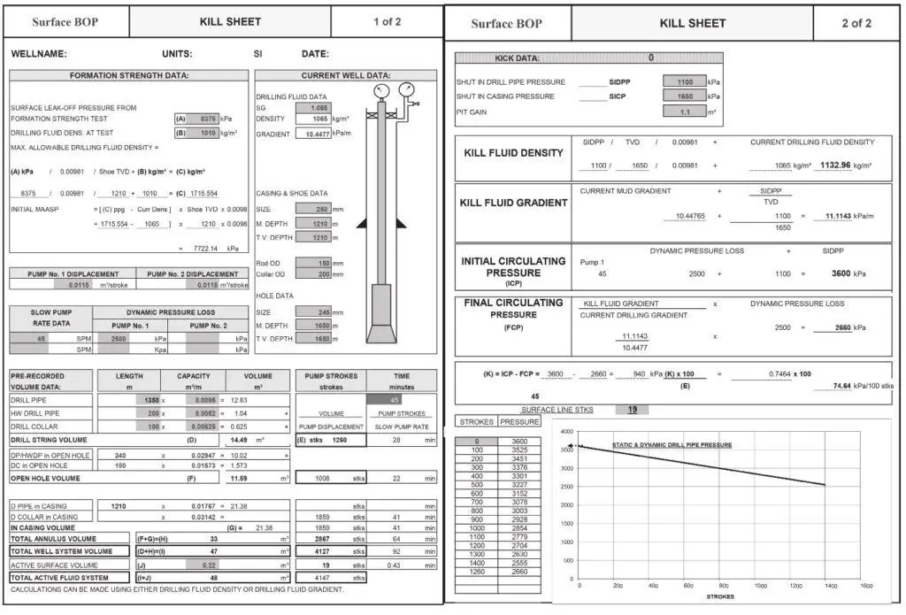
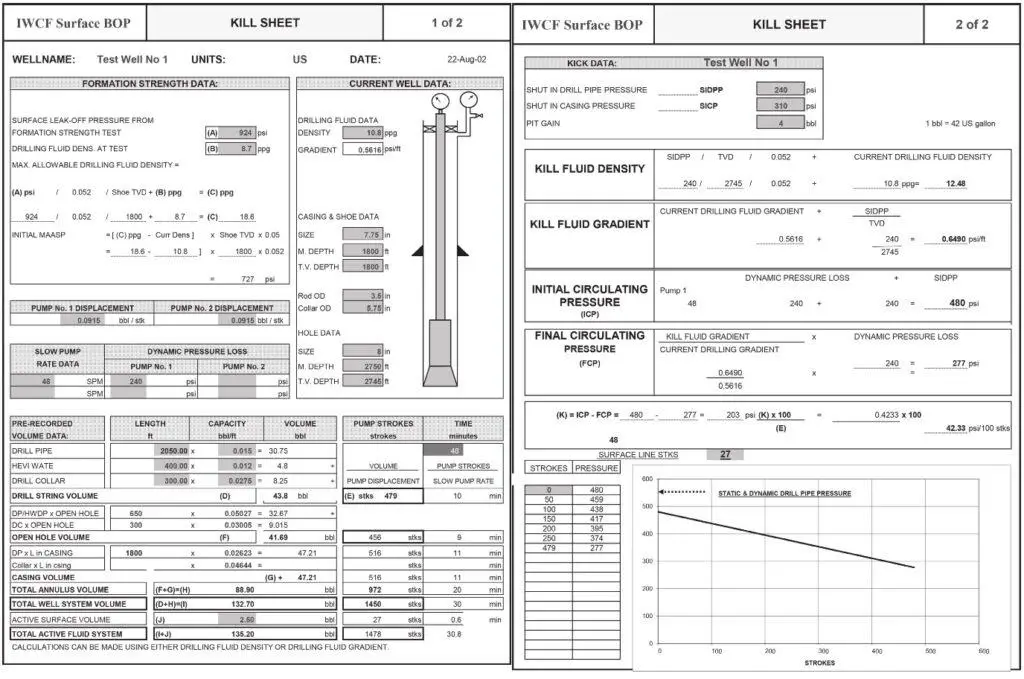
Kill sheets are used to calculate the mud weight, mud quantities, and pumping times required to bring a well back to primary control after a gas kick. A description of how to complete kill sheets will be discussed in this article.
The kill sheet is a printed form that contains blank spaces for recording information about killing an impending blowout, provided to remind personnel of the necessary steps to kill a well. The International Well Control Forum website also offers kill sheets for different units.
Importance of The Kill Sheets
Kill sheets record information required to kill a kick in the well, including mud pump rates, volumes, pressures, densities, and formation leak-off pressure. Some drills use computer programs and the collected information for the calculations. Kill sheets can supply the following information to the driller:
- Maximum shut-in annulus surface pressure (MAASP) for the original mud density.
- Required kill mud density.
- Circulating pressures.
- Time required for kill mud to get to the bit.
- Time required to fill the annulus.
The MAASP information is important to use chokes to keep the surface annular pressure lower than this value. The driller also knows when the kill mud gets to the drill bit and starts to fill the annulus. As the annulus fills, because of the heavier kill mud, the MAASP reduces towards an eventual final MAASP.
Steps Of Completing The Calculations Of Kill Sheets
Several calculations are required for the kill sheets, and they are described on the following pages, along with examples of metric and imperial kill sheets.
1 Prerecord Informations
Before the kick, and at all times, your prerecorded data sheet should be filled out except for the measured depth and the length of the drill pipe in the hole. Enter these items and calculate the internal drill string capacity and the system totals. Transfer the slow pump rate data from the prerecorded data sheet to Driller’s Method or wait and weight method kill sheet.
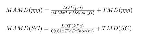
2 Information To Be Recorded in Kill Sheet When Well Kicks
Many items of information need to be gathered when a well kicks. These include:
- Old Mud Weight.
- Pit Volume Increase.
- Initial Shut-in Drill Pipe Pressure.
- True Vertical Depth Of Hole.
- Initial Shut-in Casing Pressure.
- Measured Depth Of Hole.
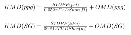
3 Determine the maximum allowable mud density
The maximum allowable mud density (MAMD) is calculated using the test mud density = TMD and the true vertical Casing pipe depth = TVD Shoe.
4 Determine the Maximum Allowable Annular Surface Pressure (MAASP)
This surface pressure depends on the mud’s weight. The MAASP can be higher for light mud, and for heavy
mud, it will be lower.
MAASP psi = 0.052 x (MAMD (ppg) – MD (ppg) x TVD Shoe (ft)
MAASP (kPa) = 9.81 x [MAMW (SG – MD (SG)] x TVD Shoe (metres)
The initial MAASP is calculated with MD equal to the original mud density (OMD). The original mud weight
is the weight of mud before the well kick occurred. The final MAASP is calculated with MD equal to the kill mud density (KMD).
Note: MAASP is rounded down in the kill sheet.
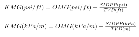
5 Find The Kill Mud Density (KMD) In The Sheet
This calculation uses the shut-in drill pipe pressure (SIDPP), the original mud weight (OMW), and the true
vertical depth of hole (TVD).
6 Find The Original Mud Pressure Gradient (OMG)
OMG (kPa/m) = OMD (SG) x 9.81
OMG (psi/ft) = OMD (ppg) x 0.052
7 Find the kill mud pressure gradient (KMG)
Where:
- SIDPP = shut-in drill pipe pressure
- TVD = true vertical depth.
8 Find The Initial Circulating Pressure (ICP)
The drill pipe circulating pressure is the sum of all friction losses, pressures caused by density imbalances, and any imposed surface backpressure. (StandPipe Pressure Calculations). ICP is the drill pipe pressure required to circulate initially at the selected kill rate while holding casing pressure at the closed-in value, numerically equal to the kill rate circulating pressure plus closed-in drill pipe pressure.
ICP = KRP + SIDPP
Where:
- KRP = the kill rate pressure or dynamic pressure loss.
If no slow circulating rate pressure has been taken, then the initial circulating pressure can be determined using the start-up procedures described in the circulations of Driller’s method.
Where the casing pressure has been held constant while the pumps are brought up to a kill rate, the drill pipe pressure reading will be the initial circulating pressure. The procedure consists of:
- Noting casing pressure reading.
- Adjusting pumps to new kill rate. Adjust the choke to hold the casing pressure constant at the value noted.
- As soon as the driller has the pumps settled on the new rate, return to the drill pipe pressure gauge.
Note this new reading as the circulating pressure for the new pump rate and maintain this.
9 Find the final circulating pressure (FCP)
FCP = KRP x OMD/KMD
Where:
- OMD = Original mud density
- KMD = Kill mud density.
10 Find Well Volumes In The Kill Sheet
Refer to Drill Pipe Capacity Calculations Formulas & Sheets for formulae and information on how to determine the following volumes:
- The internal volume of the standard drill pipe.
- Total internal drill string volume (add 1, 2, and 3).
- The internal volume of heavy drill pipe.
- The volume of the annulus of an open hole.
- The internal volume of drill collars.
- Casing Annulus Volume.
- The total volume of the annulus.
The volume per length (meter or ft) of all drill pipes should be recorded from the manufacturer’s
specification sheets.
The kill rate should be between 2-5 barrels per minute for most cases.
Aramco recommendations
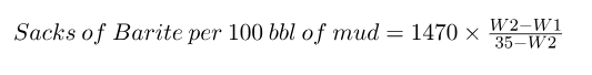
11 Barite Required to Weight-Up
It’s easy to determine the amount of barite, which will be required once the total volume to weight-up is known. Use the following formula and record its value.
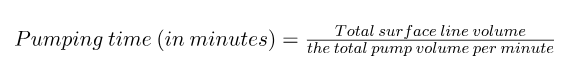
12 Determine Pumping Time to Fill Surface Lines
This is determined by dividing the surface line volume by the pump volume per minute.
Pump volume per minute = volume per stroke x strokes per minute (SPM).
If two pumps are used, then the volumes are added together to calculate the total pump volume per minute.
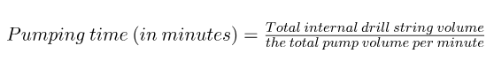
13 Determine the Pumping Time To Fill the Drill String
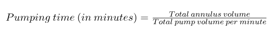
14 Determine the Pumping Time To Fill The Annulus
Download Kill Spread Sheet & Formulas
Below, we have gathered four kill sheet calculators to assist you in completing such calculations.