Pre-job Requirements
Pre-job Requirements An operating company wishing to use a Measurement While Drilling system must first decide:
- what the basic data requirements are;
- which systems currently available can meet these requirements;
- whether the limitations and specifications of the system under consideration are acceptable for this application (in terms of accuracy, data rate, temperature, etc.).
Where several different tools meet all the job requirements, some operators have a deliberate policy of trying out all the different systems to assess reliability and cost-effectiveness (check also oil well drilling well cost per foot). The MWD company chosen to provide the service will require certain information from the operator:
- when does the operator anticipate using the MWD tool (sufficient time must be allowed for workshop testing, transportation of equipment and personnel, rigging-up time at the well site);
- the expected flow rates, pump pressures, bit nozzle sizes, mud weight and other BHA components (this will affect the choice of internal MWD tool components fitted to the tool).
All the components should be thoroughly checked before the tool leaves the workshop. Directional MWD sensors should be tested on a calibration stand to simulate the expected azimuth and inclination. Some companies can install all the necessary downhole components inside the non-magnetic drill collar before leaving the workshop. It may be necessary to supply more than one tool so that, if there is a failure, another tool is already on the rig to use as a backup.
Rigging-up and Surface Checks
All MWD systems have been designed to allow a fairly simple rig-up so that normal drilling operations are not seriously held up. The service company will supply all the necessary downhole and surface equipment. To rig-up and run an MWD system usually requires two service company engineers.
The surface system requires the installation of the pressure transducer at a convenient point in the standpipe manifold. Cables are then laid to the MWD unit in the dog house or pipe deck. The rigging-up of the surface systems may require the assistance of the rig electrician or safety officer. A rig-floor display is connected up to allow the directional driller to monitor changes in the measured angles.
If the downhole components are already mounted in the drill collar, the rig-up is a simple operation, provided the collar is handled carefully. If the downhole tool has to be assembled at the rig, each individual component can be checked out. As the collar is being made up, careful attention should be paid to ensure the correct torque is applied. Rough handling of tongs and slips may damage the sensitive components inside the collar.
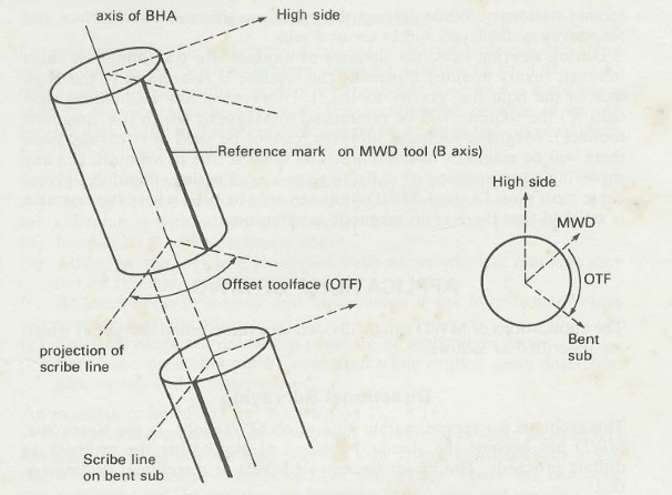
If the MWD tool is being used with a downhole motor and bent sub, the offset tool face must be measured. This is the angular difference between the actual tool face (as defined by the scribe line of the bent sub) and the toolface of the MWD tool (as defined by the position of the B axis). This may be done at the rig floor by a measuring tape or a purpose-built protractor (Fig. 1). The offset tool face must be stored in the surface computer so that the MWD tool face can be automatically converted to the actual toolface. Likewise, the magnetic declination should also be stored in the computer so that magnetic azimuth can be converted to true azimuth.
While the tool is suspended on the rig floor, it should be function-tested to ensure that all components operate correctly. A helpful test of the tool’s reliability is to take a survey at a particular depth on every trip into the hole. This is a benchmark survey, and all the results should show close agreement. The benchmark survey is usually taken below the casing shoe at a shallow depth so that if the tool is not giving the expected result, it can be tripped out without wasting too much rig time.
Normal Surveying Procedure
For directional MWD, there are two modes of operation:
- Rotary drilling, in which static surveys (azimuth and inclination) are taken after each connection or at closer intervals if required.
- Steering runs, in which a bent sub (Drilling Subs) and downhole motor are being used. In this case, it is more important to monitor the tool face as the bit is drilling.
In some tools, the operator must specify which mode is required; in other tools, both static and dynamic surveys are transmitted in sequence. The normal procedure for a static survey is to drill to kelly down, make the connection and take the survey with the bit about 5 ft off-bottom. During the 2 min. required for the sensors to measure the data, the drill pipe must remain stationary. While drilling, the pulses are transmitted to the surface and the survey is displayed within about 4 min.
During steering runs, the updates of the tool face are transmitted at short intervals (every minute). Usually the tool face is referenced to the High Side of the hole (i.e., gravity tool face). However, at low inclinations (less than 8°), the tool face will be referenced to Magnetic North (i.e., magnetic tool face). Magnetic tool face, however, cannot be used near the casing since there will be magnetic interference. The same is true of azimuth. Therefore, gyroscopic tools must be used for any surveying or orientation of deflecting tools near the casing. MWD tools can only be used where the operator is satisfied that there is no magnetic interference.
Applying for job