What Is Pipe Handling Equipment?
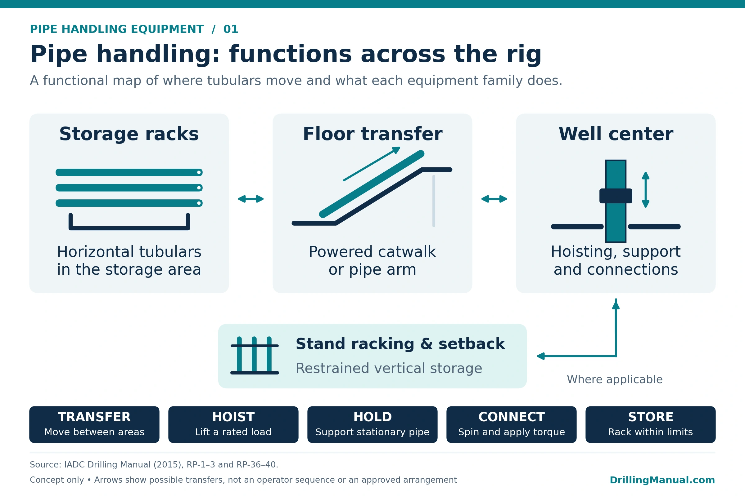
Pipe handling equipment is the group of tools and machines used to transfer, lift, support, guide, connect and rack jointed tubulars on a drilling rig. The group includes transfer equipment between the pipe racks and drill floor. Other tools handle tubulars at well center and in the setback area. The equipment arrangement changes with the operation and the type of tubular. [1]
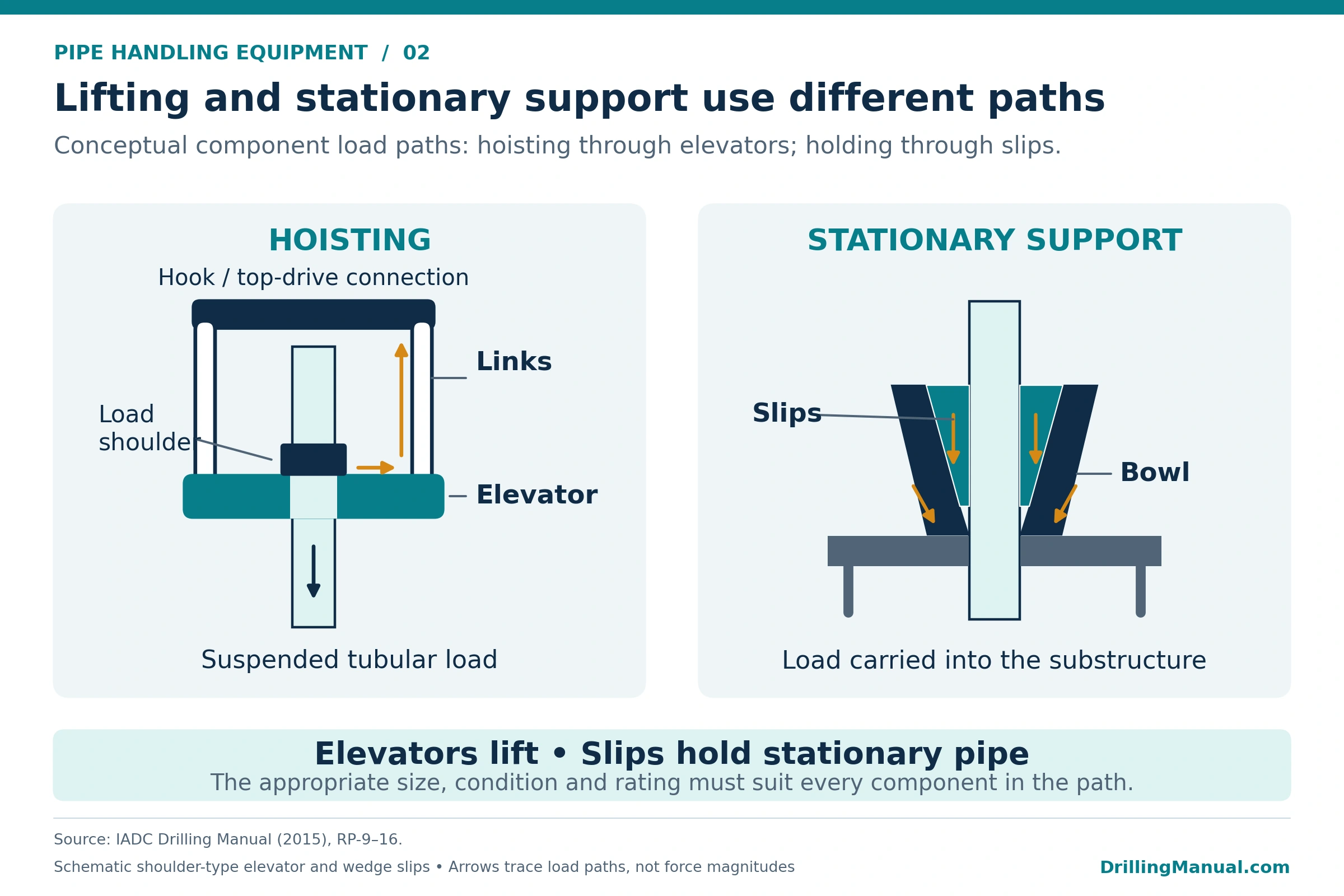
A useful starting point is to separate the work into functions. A power catwalk transfers pipe, an elevator carries a specified suspended load, and slips support the string at the floor. Meanwhile, connection equipment rotates the tubular and applies or reacts torque. These functions interact, but a tool suitable for one task does not automatically qualify for another. [1]
This guide covers jointed tubular handling on drilling and workover rigs. For the surrounding rig equipment, see the drilling rig components guide. The focus here is how the handling tools work together, how to select them, and what limits their use. [1]
Applications of Pipe Handling Equipment
The same rig may need several handling arrangements during a well. Each arrangement must account for the tubular dimensions, the load being carried and the work performed at its connections. Common applications include the following. [1]
- Adding drilling tubulars: transfer a joint or stand to the floor, position it and provide the support and connection tools needed for assembly.
- Tripping: handle stands between well center and the setback, or transfer joints to and from the pipe racks when laying down or picking up pipe.
- Running casing or tubing: match the elevator, spider, alignment tools and connection equipment to the tubular and its running requirements.
- Handling collars and other drillstring components: account for different gripping surfaces, shoulders, lengths and weights instead of assuming that the drill-pipe arrangement applies.
These applications explain why an equipment list alone is insufficient. The plan must also identify how the tubular passes between tools and where its weight is supported at each interface. Detailed tripping procedures belong alongside the equipment plan. [1]
Types of Pipe Handling Equipment and Their Functions
The following table organizes pipe handling equipment by its principal job. Some machines combine several functions, while others provide only one. The actual equipment documentation determines the permitted duty and configuration. [1] [2]
| Equipment | Main function | Selection question |
|---|---|---|
| Pipe racks, power catwalks and pipe arms | Store tubulars horizontally and transfer them toward or away from the drill floor. | Does the arrangement suit the actual tubular length, weight, diameter and floor height? |
| Elevators and elevator links | Connect a specified tubular load to the hoisting equipment. | Do the duty, load interface, geometry and condition support the intended load? |
| Slips and spiders | Support tubulars at the floor through a gripping assembly and supporting structure. | Are the gripping components, bowl, tubular size and applicable loads compatible? |
| Drill-collar safety clamps | Provide backup against downward collar movement above the slips. | Is the clamp appropriate for that backup role and component size? |
| Pipe spinners | Rotate the tubular to engage or disengage connection threads. | Does the spinner suit the gripping diameter and required movement? |
| Manual or power tongs and iron roughnecks | Apply and react connection makeup or breakout torque; integrated units also provide spinning. | Are the grip range, torque capacities, backup arrangement and working position suitable? |
| Stabbing guides and alignment aids | Help position the pin and box for connection engagement. | Does the guide fit the connection and the intended handling arrangement? |
| In-derrick rackers and manipulators | Move or guide tubulars between well center and the racking area. | Can the selected machine guide only, or also lift, at the required reach? |
| Casing running tools | Combine specified casing gripping, connection and running functions. | Which functions and ratings are provided by the particular tool? |
Pipe Racks, Power Catwalks and Pipe Arms
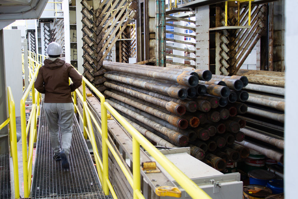
Photo: Libby Ives / International Ocean Discovery Program (IODP), JOIDES Resolution Science Operator (JRSO). CC BY 4.0. Source photo 060_exp400_C0217.jpg.
A power catwalk transfers tubulars from horizontal storage toward the drill floor and returns them during laydown. Depending on the design, a moving skate pushes a tubular along a ramp, a carrier raises it, or a hybrid arrangement combines those actions. Indexers, kickers and retaining devices manage movement between the rack and the conveying section. [1]
A pipe arm instead uses a pivoting member with grippers to carry and present the tubular. Its movement depends on the arm, pivot, actuation system and gripping components working together. Therefore, pipe-arm selection and maintenance must address the structure and grippers as well as the hydraulic supply. [1]
The critical transfer interface is where the delivered tubular becomes available to the next handling tool. Check the actual presentation position, available reach, orientation and clearance. A catwalk that accepts the pipe’s diameter may still be unsuitable for its weight, length or the rig’s floor height. Model-specific retaining and interlock features also need review; their presence cannot be assumed from the equipment name. [1]
Elevators and Elevator Links
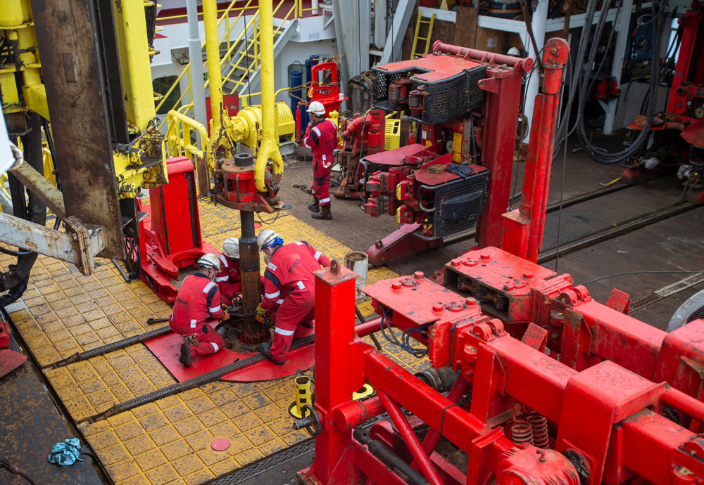
Photo: Erick Bravo / International Ocean Discovery Program (IODP), JOIDES Resolution Science Operator (JRSO). CC BY 4.0. Source photo 049_exp393_0162.jpg.
Elevators engage the tubular through an appropriate load shoulder or gripping assembly. Shoulder-type designs depend on the interface between the elevator and the tubular’s shoulder or collar. Slip-type designs use gripping elements to transfer the load into the elevator body. Elevator links, also called bails, connect the elevator to the applicable hook or top-drive arrangement. [1]
The task determines the required elevator duty. Equipment intended for handling individual joints or limited stand loads is different from equipment selected to suspend the string. Consequently, the name, bore size or appearance of an elevator does not establish permission to carry the entire string. Use the documented duty and applicable load rating. [1]
Geometry matters alongside rating. For example, a small difference between the elevator bore and the supporting tool-joint diameter can leave inadequate bearing area. Worn shoulders, bores, hinge components or link eyes introduce additional concerns. The assessment therefore includes the matching surfaces and present condition, with manufacturer clarification where the interface is uncertain. The drill pipe elevators guide provides more detailed component coverage. [1] [2]
Slips, Spiders and Safety Clamps
Slips hold the tubular at the floor and transfer its load through the supporting bowl into the rig structure. In a conventional split-cone arrangement, wedge-shaped segments engage the pipe inside a tapered bowl. The slips, inserts, bowl and tubular form a working assembly. Matching one component while overlooking the others leaves the support arrangement unresolved. [1]
Spiders provide a supporting frame and gripping arrangement for the applicable tubulars. Some elevator/spider designs can serve different roles when configured accordingly. Their permitted application, inserts and operating arrangements must come from the equipment documentation. The separate drilling slips guide explains this equipment in greater detail. [1]
A drill-collar safety clamp has a backup role above the slips. Its presence does not replace the need for the correct slips and support arrangement, nor does it establish a separate hoisting rating. Keep this distinction clear when preparing the tool list for collars and other components with different handling features. [2]
Spinners, Tongs and Iron Roughnecks
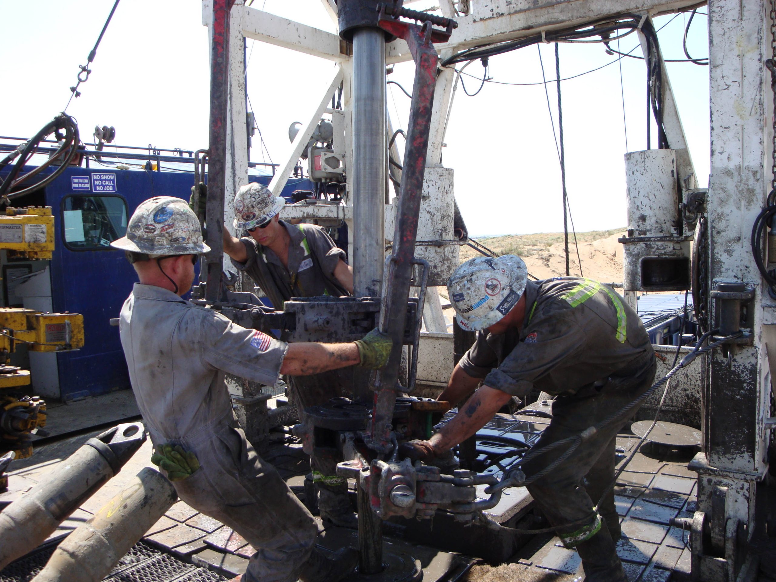
Photo: Elaine Cullen / NIOSH, via Wikimedia Commons. Public domain (U.S. government work). Source photo 8744524276.


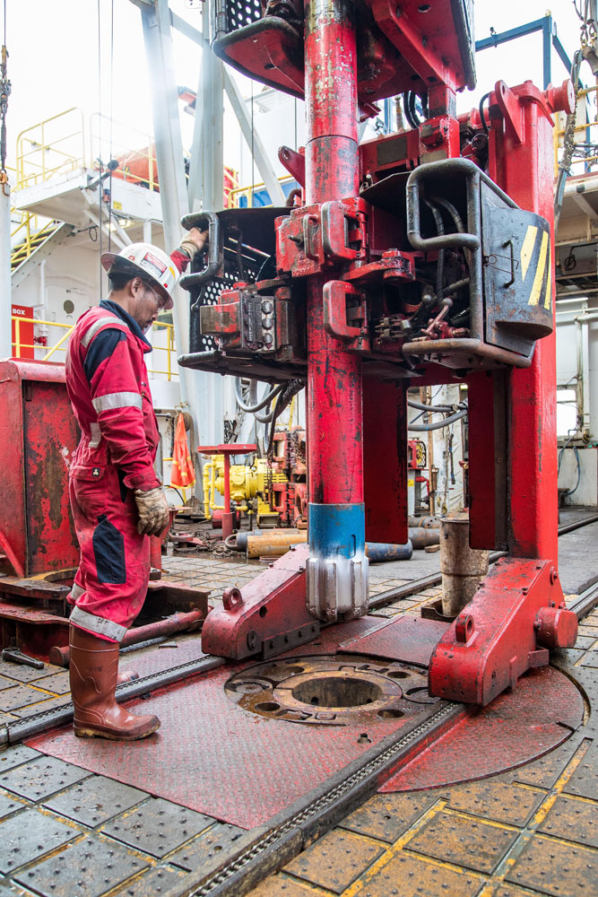
Photo: William Crawford / International Ocean Discovery Program (IODP), JOIDES Resolution Science Operator (JRSO). CC BY 4.0. Source photo exp376_071.
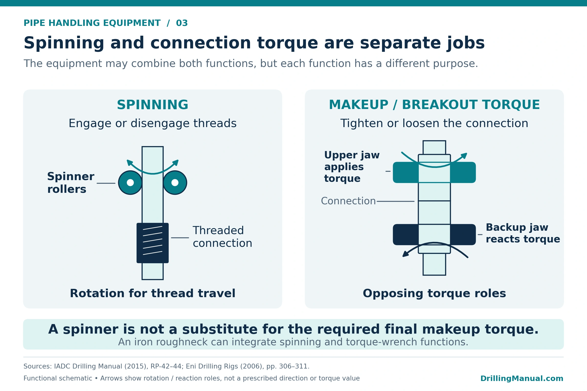
A pipe spinner rotates the upper tubular while the connection threads engage or disengage. Final makeup and initial breakout require a suitable torque-applying arrangement. Thus, successful spinning does not demonstrate that a connection has received its specified final makeup torque. These are separate functions even when one machine performs both. [1] [3]
Manual tongs grip the connection members and transmit the applied torque and its reaction. Here, “manual” describes the crew’s handling of the tongs; an external pulling system may still supply the force. The tong, jaws, lines and anchoring arrangement must suit the intended duty. Their stored energy and moving parts also create hazards that belong in the operating plan. [1]
An integrated iron roughneck brings together positioning, spinning and torque-wrench functions. Its upper and lower gripping assemblies apply torque across the connection while providing a reaction. Casing power tongs and other connection tools can have different arrangements, so the term “power tong” alone does not identify every installed function. [1] [3]
Selection must distinguish spinner capability, makeup capacity and breakout capacity. Connection height, horizontal reach, gripping range and the backup arrangement also matter. A machine with adequate torque may still be unable to reach or grip the connection correctly in the available floor space. [1]
Racking Systems, Setbacks and Fingerboards
Racking stores connected tubulars as stands during a trip. The stands occupy positions in the setback and fingerboard arrangement. Both physical space and the allowable structural loads constrain the stored inventory. In particular, the permitted setback load may depend on the load carried at the rotary at the same time. [1]
Different in-derrick machines provide different levels of assistance. A manipulator may guide the upper end while other equipment and personnel handle the lower end. A lifting racker can support and move the stand, subject to its rated duty and reach. Consequently, a powered arm should not be assumed to provide complete stand handling simply because it reaches the fingerboard. [1]
The machine also imposes loads on its mounting structure and needs suitable operating clearance. A retrofit may therefore involve structural support, fingerboard modifications and service connections, as well as installation of the machine itself. These interfaces belong in the equipment selection review. [1]
Casing Running Tools and Alignment Aids
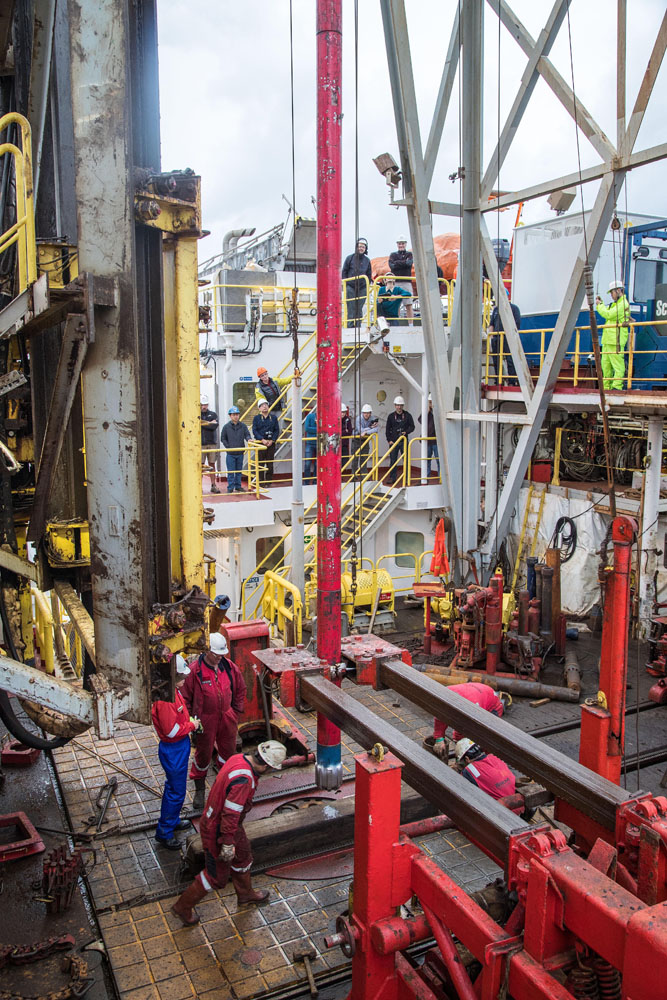
Photo: William Crawford / International Ocean Discovery Program (IODP), JOIDES Resolution Science Operator (JRSO). CC BY 4.0. Source photo exp376_072.
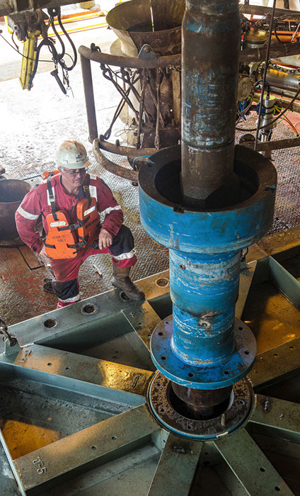
Photo: William Crawford / International Ocean Discovery Program (IODP), JOIDES Resolution Science Operator (JRSO). CC BY 4.0. Source photo exp367_127.
A conventional casing-handling arrangement combines the appropriate elevator and spider with alignment and connection tools. During engagement, the stabbing guide helps align the pin and box. A torque-turn system can record the connection makeup response for assessment against the tubular manufacturer’s criteria. Each tool supplies a different part of the required work. [1]
A casing running tool may combine gripping, makeup, rotation, reciprocation, filling or circulation functions. Availability varies by design. Therefore, specify the functions actually required and check the individual tool’s load, torque and pressure limitations. The presence of a CRT does not establish that every listed function is available. See the companion casing running guide for the wider operation. [1]
Manual, Powered and Automated Pipe Handling Equipment
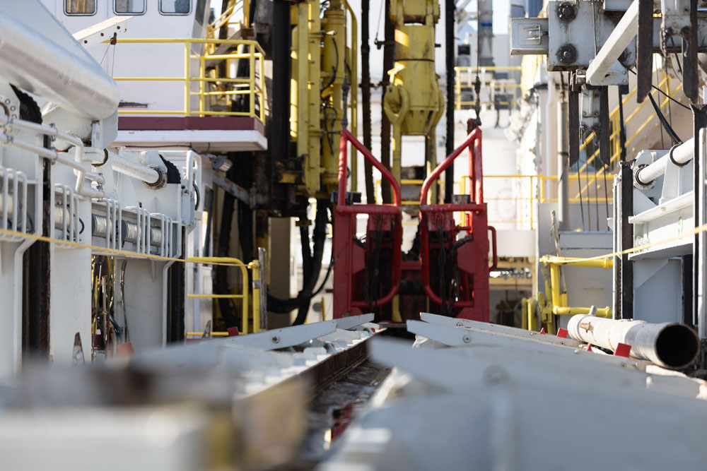
Photo: Tiffany Liao / International Ocean Discovery Program (IODP), JOIDES Resolution Science Operator (JRSO). CC BY 4.0. Source photo 310_exp403_1426.jpg.
Mechanization changes how a task is performed and where people interact with it. It can reduce direct handling, but the result depends on which functions have been mechanized and how the equipment integrates with the rig. Review the actual division of work instead of assigning a capability from a label. [1]
| Arrangement | Typical division of work | Important limitation |
|---|---|---|
| Manual handling with powered assistance | People position or latch equipment; a hoist, cathead or another power source supplies motion. | Powered force does not remove the need to manage manual handling and exposure around the equipment. |
| Powered or remotely operated tools | The operator commands machine functions from local or remote controls. | Remote control does not establish that the whole task is automatic or that every transfer is covered. |
| Integrated or automated systems | Linked controls and machines perform specified portions of the handling and connection cycle. | Capability still depends on the equipment configuration, sensors, interfaces and trained operation. |
The top-drive pipe handler is one part of this wider arrangement. Its associated elevators, links and backup wrench serve the top drive’s handling and connection duties. A catwalk or stand racker performs a different task elsewhere in the system. Likewise, the rig hoisting system supplies the lifting capability with which the handling tools must be compatible. [1]
How to Select Pipe Handling Equipment
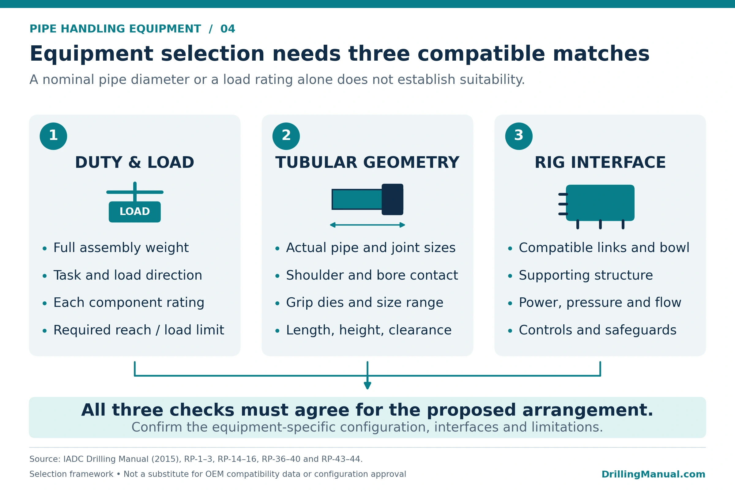
Selection begins with the work the equipment must perform. Describe the tubulars, the load to be supported, the movement required and the connection work involved. Then check whether the complete arrangement can perform that duty within its documented limits. Pipe handling equipment must fit both the tubular and the rig. [1]
Define the Handling Duty and Capacity
Record the heaviest item or assembled stand that the transfer equipment will handle. For string-support equipment, assess the relevant suspended string load as well. The elevator, links, slips, bowl and supporting structure have different roles and individual limitations. A high rating on one component does not establish the capacity of the complete load path. [1]
Hoisting power, braking capability and structural capacity also answer different questions. A system may have enough power to move a load while an individual component lacks the required strength. Conversely, sufficient strength does not establish the speed at which the load can be moved. The equipment assessment must address each applicable requirement. [1]
For connection equipment, distinguish spinner performance, makeup torque and breakout torque. These are separate entries in the equipment specifications. The required connection torque must also remain appropriate for the tubular connection; the wrench’s maximum rating is not itself a makeup instruction. [1] [3]
Check Tubular Size and Contact Geometry
Outside diameter is only part of the fit assessment. Actual length and weight matter to transfer equipment. For an elevator, the bore and the mating shoulder or gripping arrangement affect how the load enters the tool. Wear on either contact surface can reduce the supporting area. The elevator and tubular therefore need assessment as a working pair. [1] [2]
Similarly, slips need the correct relationship between the pipe, gripping inserts and bowl. Incorrect sizing changes the contact pattern and can damage the pipe or the slips. Compatible replacement parts and their condition remain important even when the tool’s nominal size appears correct. [1]
Confirm Rig Interfaces and Services
The handling route must fit the available space. A catwalk’s specification includes tubular length, diameter and weight together with floor height and its own dimensions. A racker needs the required travel and access to the fingerboard. Connection equipment must reach the intended connection position and height. Check these interfaces together before selecting an arrangement. [1]
| Interface | Selection question |
|---|---|
| Supporting structure | Can the mounting and surrounding structure carry the machine and its applicable handling loads? |
| Working envelope | Does the equipment have the required reach, height adjustment, travel and clearance? |
| Hydraulic and other services | Do the available supplies match the selected equipment’s requirements? |
| Controls | How will local, remote or integrated controls coordinate the equipment’s functions? |
| Setback and fingerboard | Do stand height, tubular diameter, available positions and allowable loads fit the planned inventory? |
For example, a hydraulic power unit supplies a particular pressure and flow capability. Its presence alone does not establish compatibility with every hydraulic tool. Likewise, fitting a racker can require changes to its supporting structure and finger arrangement. These are engineering interfaces, not simply matters of finding an empty position on the rig. [1]
Factors Affecting Pipe Handling Performance and Limitations
Pipe handling performance depends on the complete system’s condition and configuration. Reach is one example: a racker’s permitted lifting load may decrease as the arm extends. Consequently, the relevant capacity is the capacity at the required working position. A single headline load figure may leave that condition unresolved. [1]
Gripping condition is equally important. Worn dies can reduce a pipe arm’s ability to retain a tubular. Uneven slip inserts can concentrate load instead of distributing it across the intended contact area. Elevator shoulder wear can also alter the load-bearing interface. These changes affect performance without changing the nominal size marked on the tool. The separate slip-crushing guide develops that particular loading issue in more detail. [1] [2]
Powered equipment also depends on its hydraulic, electrical and control systems. The manuals identify fluid condition, lubrication, hoses, sensors, retaining elements and structural condition as maintenance concerns. The available safeguards vary with the design. Assess the installed features and their working condition instead of assuming that every machine has the same interlocks. [1]
Finally, a machine’s cycle time describes only part of the operation. Tubular delivery, support, alignment, connection work and racking involve several pieces of equipment and their operators. A quicker wrench cycle alone therefore does not establish a reduction in the complete connection or tripping time. This is a system-level interpretation of the separate handling functions described by IADC. [1]
Pipe Handling Equipment Safety: Common Mistakes
Several handling problems begin when a tool is used for a function it was not selected to perform. The following examples connect the equipment’s role with the resulting hazard. [1]
| Mistake | Why it matters |
|---|---|
| Using slips to stop descending pipe | The resulting impact can overload the gripping assembly and damage the tubular. Slips provide stationary support; the hoisting and braking system controls motion. |
| Accepting partial elevator-latch engagement | The intended closure and retention have not been established. Apparent contact with the pipe does not demonstrate a secure lifting arrangement. |
| Mixing gripping inserts with uneven wear | The contact load can concentrate on part of the assembly instead of being shared as intended. |
| Ignoring tong reaction and stored energy | A loaded tong and its associated parts can release energy violently if a component fails. |
| Assuming remote control removes pinch points | Moving jaws, carriers and arms still create crush and pinch hazards. Their safeguards and operating interfaces remain part of the equipment assessment. |
Worked Example: Pipe Setback Capacity
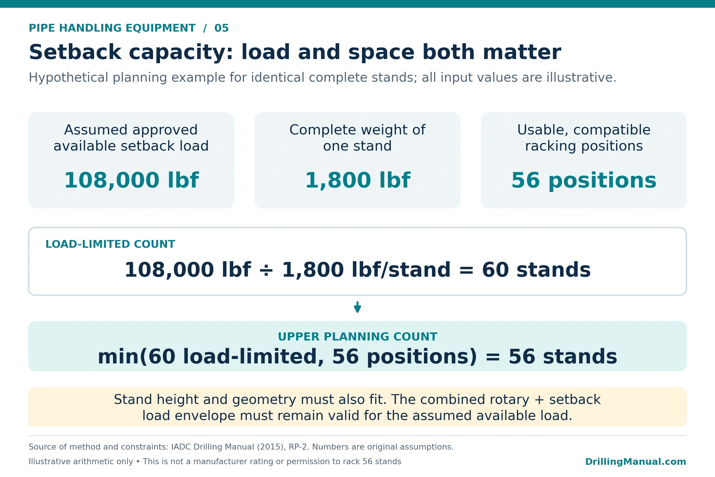
IADC describes two constraints on pipe stored vertically in the derrick: the available racking space and the allowable load carried by the setback structure. It also notes that setback capacity can depend on the load carried at the rotary. A planning calculation must therefore use the manufacturer’s applicable combined-load information. [1]
The following values are hypothetical. Assume that an engineering assessment has allocated the available setback load for the intended combined load case. Every complete stand in this example has the same weight.
| Input | Assumed value |
|---|---|
| Available allowable setback load for this load case | 108,000 lbf |
| Weight of one complete assembled stand | 1,800 lbf per stand |
| Usable positions for these stands | 56 |
Load-based count = 108,000 lbf ÷ 1,800 lbf per stand = 60 stands.
Upper planning count = smaller of 60 load-based stands and 56 usable positions = 56 stands.
At that count, the example inventory weighs 56 × 1,800 = 100,800 lbf. Physical space controls the result. The unused portion of the assumed load allowance does not create extra racking positions.
This calculation screens only the stated load and position constraints. Stand height, fingerboard geometry, support condition and the approved combined rotary/setback load case must also fit. For mixed stand weights, use the actual inventory weights rather than applying one average weight without review. The result is an illustrative planning bound, not authorization to rack 56 stands on an actual rig. [1]
Inspection and Maintenance of Pipe Handling Equipment
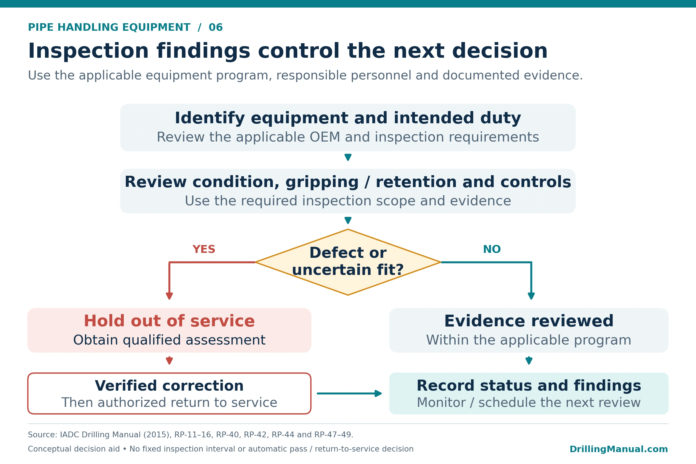
An inspection program must suit the equipment, its service and the applicable requirements. IADC describes observation, usage and elapsed time as possible triggers for inspection. These approaches need records: someone must track the equipment’s use, observe its condition and compare the findings with the required action. [1]
Inspect the Working Interfaces
Inspection should address how the equipment carries or controls the load. For elevators, this includes the mating surfaces, hinges, latch components and retention arrangements. Slip assessment includes the bodies, dies, retaining features and bowl condition. Visible appearance alone may not resolve dimensional wear or cracking; the required examination depends on the component and the applicable procedure. [1] [2]
On mechanized equipment, the assessment extends to gripping and retaining devices, structural members, pivots, hoses and controls. Sensors and safety features also need attention because they influence how the equipment functions. Lubrication and hydraulic-fluid management belong in the maintenance plan alongside examination of the load-bearing parts. [1]
A reported defect needs evaluation against the appropriate criteria and a recorded response. For example, IADC requires an elevator of uncertain operating condition to leave service while its condition is reviewed. The decision about repair, replacement and return to service must follow the requirements for the actual equipment. A general article cannot supply one acceptance limit for every tool. [1]
Inspection Records for Pipe Handling Equipment
The maintenance system should identify the equipment, the applicable work, the responsible people and the reporting requirements. Records need to show when work was performed, what was found and how the finding was addressed. Usage tracking is particularly important where an inspection or maintenance task depends on operating time. The rig inspection checklist provides a broader equipment-review companion. [1]
The manuals contain example intervals and component-specific checks. Their numerical schedules should retain their original context. Establish the current program from the manufacturer’s documentation, the operator’s requirements and applicable inspection obligations. Where specific maintenance information is missing, IADC recommends developing the program with appropriate maintenance or engineering expertise. [1]
Practical Rules of Thumb for Pipe Handling Equipment
These qualitative rules help organize equipment review. They do not replace the selected tool’s documented limits. [1]
- Describe the duty before comparing ratings. Identify whether the tool transfers a joint, supports a stand, suspends a string or applies torque.
- Check the complete load path. Each supporting component and interface must suit the intended load.
- Assess fit and condition together. Nominal size does not account for worn shoulders, gripping surfaces or incompatible inserts.
- Use capacity at the working position. Reach and configuration can affect a handling system’s permitted load.
- Check both space and weight for setback planning. Satisfying one constraint does not establish the other.
- Keep design margin separate from operating allowance. A design safety factor does not permit loading above the equipment rating. [3]
- Include controls in maintenance. Grippers, sensors and protective functions need attention alongside structural parts.
Limitations and Source Scope
This guide explains equipment functions and assessment principles from the identified manuals. Their editions matter: historical descriptions of available machines, standards and example capacities do not establish today’s complete product range or current specification requirements. Numerical equipment limits must come from documentation applicable to the selected tool. [1] [2]
The diagrams simplify the relationships between equipment and duties. They are not installation drawings, operating sequences or repair instructions. The setback example uses original hypothetical inputs to illustrate the calculation principle; it supplies no actual rig rating.
IADC also states that its manual does not take precedence over manufacturers’ or operators’ instructions. Use the overview to identify the right questions, then resolve them through the equipment documentation and the rig’s approved arrangements. [2]
Frequently Asked Questions About Pipe Handling Equipment
Does Fitting the Pipe Diameter Prove the Tool Has Enough Capacity?
No. Size compatibility and load capability require separate checks. The contact geometry, operating position, component condition and intended duty also matter. An elevator may fit around a tubular while the supporting shoulder area or the complete load path remains unsuitable for the required load. [1]
Can a Single-Joint Elevator Carry the Whole String?
Its name does not establish full-string capability. IADC distinguishes limited handling duty for a joint or, in some designs, a stand from higher-capacity string handling. Confirm the selected elevator’s permitted duty and rating. A tool that handles one assembled item is not thereby qualified to support the complete string. [1]
Does an Iron Roughneck Hoist the Pipe?
The integrated wrench described here spins and torques connections. Both tubular sections require suitable support during that work. The wrench’s ability to clamp a connection does not establish that it can replace the elevator, slips or other equipment assigned to support the tubular load. [1]
Are All Hydraulic Handling Tools Automated?
No. Hydraulic power describes how a function is driven. The operator may still control it with local levers or a remote console. Several control arrangements appear in the manuals, including integrated and automated functions. The actual operating mode depends on the installed machine and control system. [1]
How Often Should Pipe Handling Equipment Be Inspected?
There is no single interval for the entire equipment group. The program must address the particular component, its service, observed condition and applicable requirements. Manufacturer guidance, defined responsibilities and records allow the inspection schedule to be applied and reviewed. Example intervals in a manual require their original equipment context. [1] [2]
Can Powered Handling Equipment Be Retrofitted to an Existing Rig?
A proposed installation needs an engineering review of mounting loads, available space, movement envelopes, services and controls. An in-derrick racker may also require structural and fingerboard changes. Physical space for the machine is only one part of the compatibility assessment; the selected design determines the required integration work. [1]
What Is Range 3 Drill Pipe, and Why Does Length Matter?
Range 3 is a drill-pipe length classification. IADC’s 2015 manual lists 38–45 ft for Range 3 drill-pipe tubes. For handling selection, check the actual finished-joint or stand length and weight, including the assembled configuration. The range label alone does not establish catwalk, pipe-arm or racking compatibility. See API drill pipe specifications and length ranges for the broader tubular reference. [1]
Which Standards Should Be Checked for Pipe Handling Equipment?
The IADC 2015 framework discusses API 7K for relevant drilling equipment and API 8C for hoisting equipment. It also refers to API RP 7L and RP 8B for inspection and maintenance of their respective equipment groups. The applicable document depends on the tool and service. These are references identified in that source edition, not a statement of the current clauses or proof of equipment compliance. [1]
References
[1] International Association of Drilling Contractors. IADC Drilling Manual, 12th edition, 2015. Chapter Rotating and Pipehandling Equipment (RP), especially RP-1–3, RP-9–16, RP-23–25, RP-33–44 and RP-47–49; Chapter Drill String (DS), DS-1 for drill-pipe tube length ranges.
[2] International Association of Drilling Contractors. IADC Drilling Manual, 11th edition, eBook Version V.11, copyright 2000. Chapter E, Pipe Handling Equipment, especially E-15–30 and E-34–36. The chapter’s historical examples retain their original equipment and service context.
[3] Eni Corporate University. Drilling Rigs, Libya ENABV Training Project, code IPE044-E-P-A01, Revision 001, date printed 10/11/2006. Chapter 29, pp. 286–313, especially the equipment-rating, elevator, slip, spinner, tong and pipe-racking sections.