This article will explain the use of drilling rig hoisting systems, including wire ropes and, in particular, the block line.
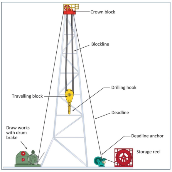
The hoisting system is one of the drilling rig components, that consists of the following:
- The Drawworks.
- Drawworks Brake System.
- Crown Block.
- Traveling block.
- Hook.
- Links and elevators.
- Wire rope (block line).
- Deadline anchor.
The same engines drive the drawworks and rotary via a transmission when using a diesel-mechanical drive. On diesel-electric driven rigs, the rotary and drawworks have their independent motors.
Steel wire ropes are widely used on drilling sites. Examples are the block line, sand line, cat line, guy lines, and slings. This Topic briefly explains the most commonly used terms applied to steel wire ropes, plus some notes on their use.
The most crucial wire rope on a drilling rig is the drilling line, which has to support the entire weight of the drill pipe or casing in the well. This Topic describes the handling and use of the block line, some of the equipment used in association with it, and, most importantly, the techniques used to maximize its service life.
Drilling Rig Hoisting System
The entire hoisting installation comprising draw-works, drum, and brakes is shown schematically in Figure 2.
Factors to be considered when a hoisting system is designed or chosen are:
- The maximum required hoisting load.
- The maximum speed at which we can pull the loads.
- The strength of the line.
- The maximum speed at which we can raise an empty block.
All these factors are strongly related to the:
- Power and rpm of the motor.
- Transmission.
- Drum diameter.
These factors and the number of lines strung in the system determine the hook load and the speed at which it can be handled. Nowadays, some drilling rig types have a fully hydraulic raising and lowering system instead of the conventional drum and wireline drawworks system. Some of the main features of such a system are:
- Reduced weight and space requirement.
- Improved safety.
- Highly accurate stroke movement.
- Better braking capacity.
- Automatic heave compensation for floating drilling.
- Eliminate the time spent on wire rope maintenance (slipping and cutting) and replacement.
Whether hydraulic hoisting systems will eventually replace the drawworks will depend on reliability, economics, and experience with the current systems.
Drawworks System
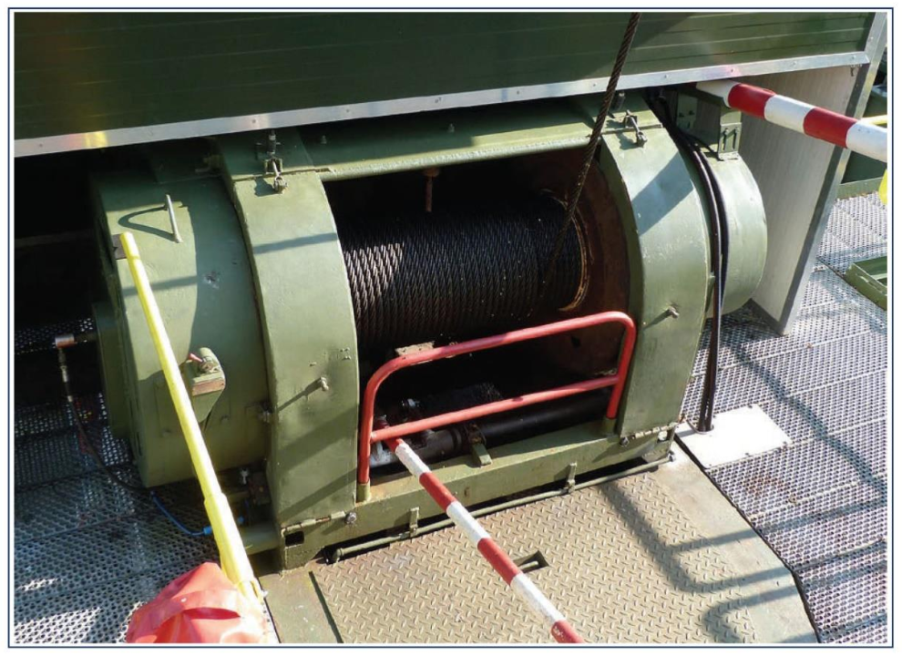
Figures 3 & 4 are pictures of a draw-works with an auxiliary electro-dynamic brake. The drive can be either diesel mechanical or diesel electrical.
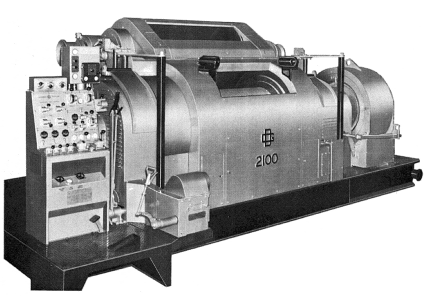
Shafts with sprockets and chains provide the internal drive transmission. A gear wheel has a connection to the main drive for reversing. Shifting the sprocket to one side will engage a jaw clutch, making forward movement possible. Typically, we use a toothed clutch on the jackshaft to shift into low or second gear. Drum, rotary, sand reel, and cat head are all clutch activated. Figures 5 & 6 show the arrangement of a typical unit.
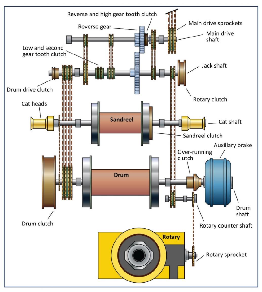
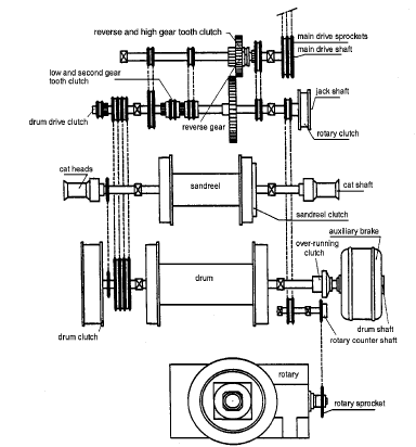
Figures 5 & 6 show twin drum draw-works. The upper (and rear-most) drum is to accommodate a sand line.
Drum Role In The Drilling Rig Hoisting System
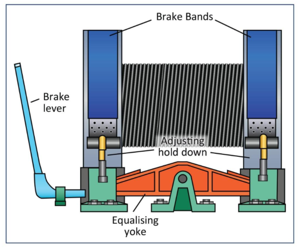
The drum is an essential part of a hoisting system. The size depends on the height of the derrick or mast. Its surface should be grooved so that spooling is controlled and the wire is not deformed. A wedge-shaped guide against the inside of the flange, together with turnback rollers on a bracket above the drum, eases the line over for its return wrap. The flanges are wide to accommodate the mechanical brake bands (Figures 7 & 8).
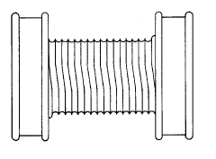
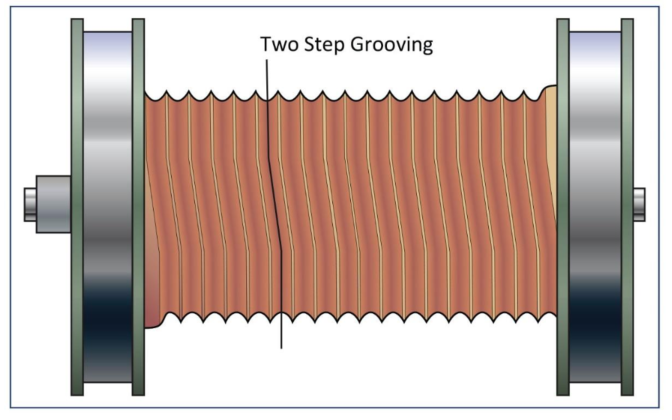
On most drums manufactured nowadays, one-step (called parallel) or two-step (called counter-balance) grooving is used, as shown in Figure 9. These patterns prevent line build-up at the cross-over points (places where one line crosses over a previous wrap).
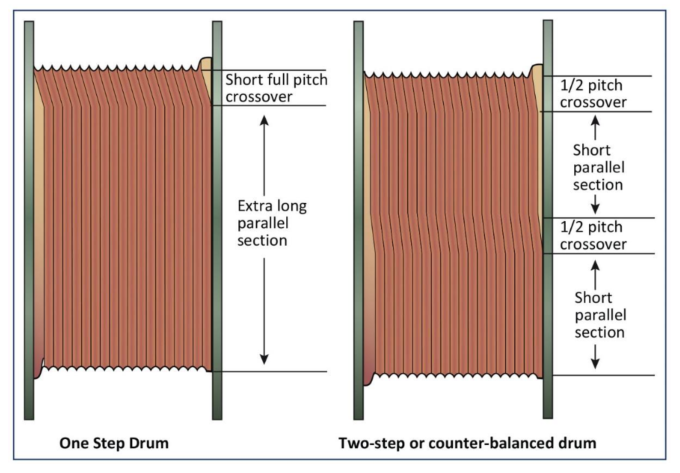
In two-step grooving, we can divide the grooves into two sections where the grooves run parallel to the drum flanges and where the grooves run spirally. These grooves guide the line spooling, which prevents the drum from getting out of balance. In addition, it reduces line whip between the drum and crown block when spooling at high speed.
One-step grooved drums are suitable for two or three layers of line only. Counter-balanced or two-step grooved drums with only half the pitch angle give good spooling with many more layers of lines. The spooling is faster with less line scrubbing and whipping.
Brakes
We can divide the drawworks brake system into:
- Main brakes; these are the mechanical brakes on the drum flanges or a hydraulic/mechanical disc brake system.
- Auxiliary brakes; can be hydrodynamic, electrodynamic, or magnetic particle brakes.
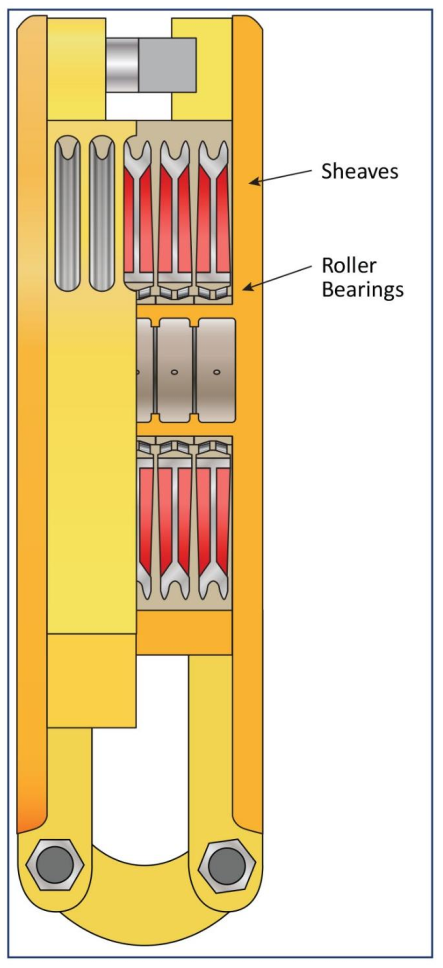
Sheaves In Drilling Rig Hoisting System
The sheaves in drilling rigs have a large diameter, often 1.5m (60″) or more, to reduce fatigue in wire ropes and increase the endurance of the cable. The diameter depends on the size of the wire rope used.
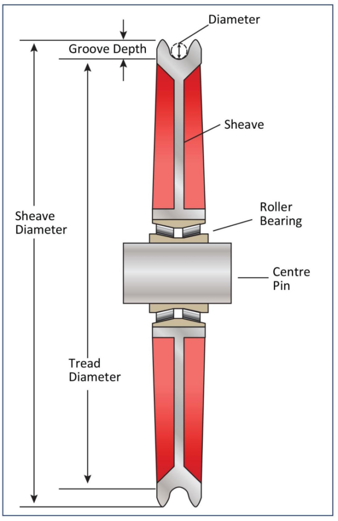
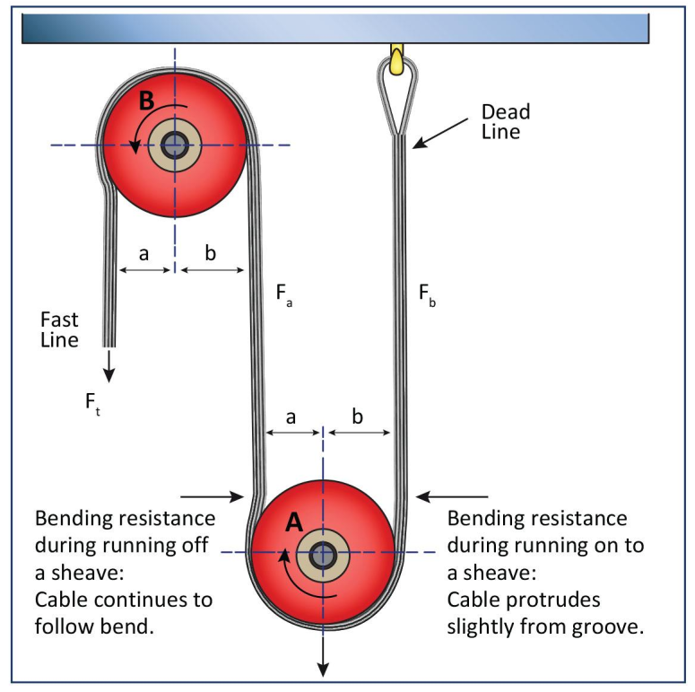
Generally, the sheave diameter is vital because bending the line around the sheave will cause a wear on the line (see Figure 11). When the large-diameter lines are constantly flexed over sheaves in the blocks, the friction of the wire against the wire and strand against strand becomes severe. The smaller the sheave (and the larger the number of sheaves), the greater the wear.
Groove
To guide the line and prevent it from jumping off the sheave, the grooves in the crown and traveling block sheaves have a depth of between 1.33 and 1.75 times the wire rope diameter, and the sides of the groove subtend an angle of 30° – see Figure 13. For a new sheave, the radius of curvature of the bottom of the groove must be between 1.06 and 1.1 times the radius of the wire rope. The groove usually supports 150° of the wire rope circumference.
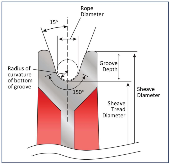
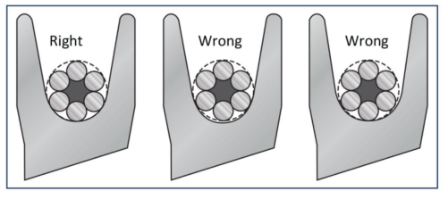
If the groove on the drilling rig hoisting system sheave is too narrow for the wireline, abrasion will be excessive both on the rope and on the sides of the sheave. If the groove is too wide, the rope will lack lateral support and tend to flatten as it passes through the sheave.
The ideal relation between groove and rope is shown in Figure 14. During its service life, regular wear will cause the dimensions of a groove to change until it is no longer acceptable. The groove radius, therefore, must be checked regularly to determine when reconditioning is required. Sheave groove gauging practice and size limits for worn grooves are given in API RP 9B.
Bearings
Nowadays, sheaves have roller bearings that are mounted onto the block shaft. The diameter of this shaft could be as great as 25.4 cm (10″).
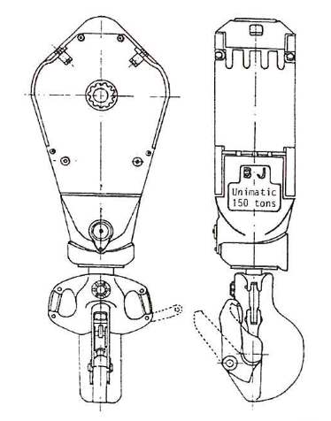
The Blocks
Block assembles are a significant drilling rig hoisting system that we can describe as large pulleys or sheaves mounted on a standard shaft. There are two in the system:
- The traveling block that goes up and down inside the derrick or, in the case of a mast, alongside it.
- The crown block that, as the name suggests, remains at the cop of the derrick or mast. It usually has one sheave more than the traveling block.
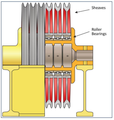
Figure 16 & 17 shows a crown block and a traveling block. There are various types of crown blocks; compare Figure 15 (used on derricks) with Figure 16 (used on masts).
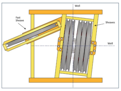
On derricks, the crown block can be adjusted slightly if the traveling block is not exactly in line with the center of the well.
The Hook In The Drilling Rig Hoisting System
Generally, the hook, from which are suspended the various tools used for raising and lowering the drill pipe, drill collars, casing, erc., is either suspended from the traveling block or is an integral part of it (Figures 18 & 19). It can rotate on bearings in its housing but can also be locked in various positions.
There is an intense spring between the hook’s shank and the housing to pretension the stand of the drill pipe so that the tool joint thread will jump out automatically when spinning on the pipe. A second function of the spring is to absorb shocks while pulling the pipe out of the drilling slips.
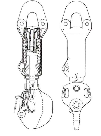
The hook has a safety latch for the swivel and link ears at both sides for the elevator link attachments. In addition, we lock the hook during drilling to prevent it from turning with the oil and gas Kelly. Furthermore, the hook and the drill string must be free to rotate while round-tripping pipe, especially when the drilling assembly is in the open hole. Typically, we may lock the block while the assembly moves through the cased section. In modern hooks, an automatic hook positioner ensures the hook and elevator turn into the correct position for the derrickman.
Hook/Block Combination
The total length of an integral hook/block combination has the advantage of being considerably shorter. The fact that we should take the entire assembly has to be taken to the workshop if only the hook has to be repaired could be said to be a disadvantage.
The Elevators
General rig elevators support the drill pipe, casing, or tubing while raised from or lowered into the hole.
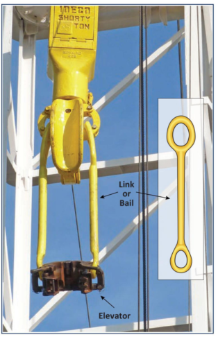
We usually use elevator links or bails to attach elevators to the hook (Figure 20). They provide clearance for the tool joint while latching the elevator around the pipe. Elevators are relatively simple pieces of equipment. However, we must not forget that they must carry the weight of the entire string and often additional tensile forces resulting from over-pulls and shock loads. As the drilling rig crew is working underneath this equipment, a poorly maintained and, therefore, unsafe elevator could lead to fatal accidents. Regular checks as to whether the elevator is in proper condition are essential.
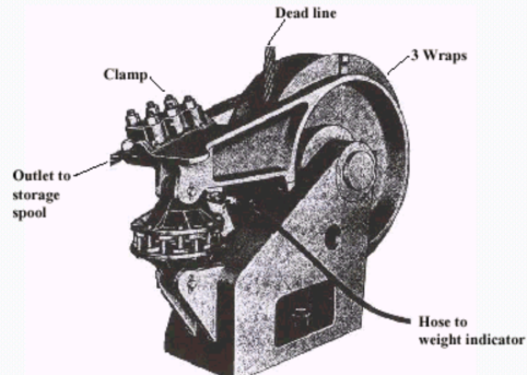
Dead Line Anchor
Anchors the last line from the crown block and stores the drilling line on a reel. This allows new lengths of line to be fed into the system to replace the worn parts of the line moving on the pulleys of the crown block or the traveling block. The worn parts are regularly cut and removed by a process called: Slip and Cut Practice. Slipping the line, then cutting it off helps to increase the lifetime of the drilling line.
Top Drive Drilling System For The Rig Hoisting Operations
The time required to add singles during drilling is nonproductive time. The drilling operation becomes more efficient if adding a stand. However, Kelly’s length makes this impossible using standard drilling equipment. There was a deep need for a different way of rotating the pipe, not requiring a kelly, and the top drive drilling system provided a means of doing this.
Top-drive drilling systems have become a standard in the industry for increasing capability and improving the efficiency of drilling operations. There is no requirement for the traditional Kelly and bushing when using a top drive. This is because the drill string will rotate directly by an electric drive system suspended from the traveling block. We usually use the guide tracks to provide torque reaction in the derrick.
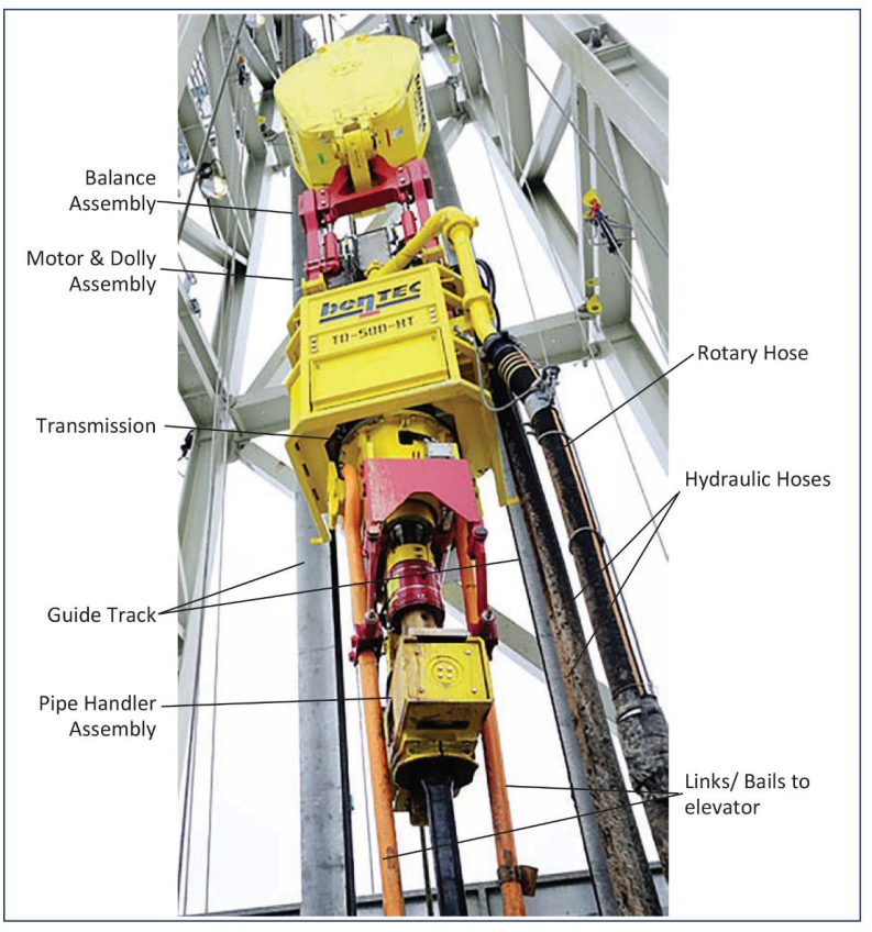
Manufacturers have designed the system to handle 28m (93 ft) stands, eliminating two-thirds of the conventional drilling connections. The top drive drilling system allows the driller to make up and break out the drill string from the drive drilling subs and to open and close the internal BOP valve at any height in the derrick using the integral pipe handler. Figure 31 is a description of a top-drive drilling system.
Drilling Line In Rig Hoisting System
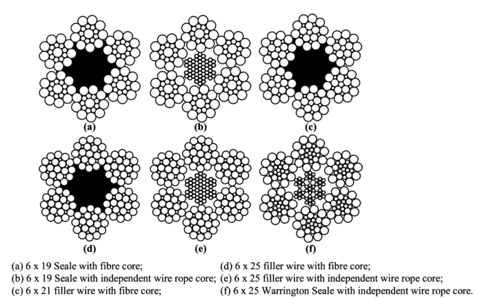
The drilling line is basically a wire rope made up of strands wound around a steel core. Each strand contains several small wires wound around a central core.
The drilling line is of the round strand type with Lang’s lay. The drilling line has a 6×19 construction with Independent Wire Rope Core (IWRC). This construction implies six strands, each containing 19 filler wires. The size of the drilling line varies from ½ “to 2 “.
Notes:
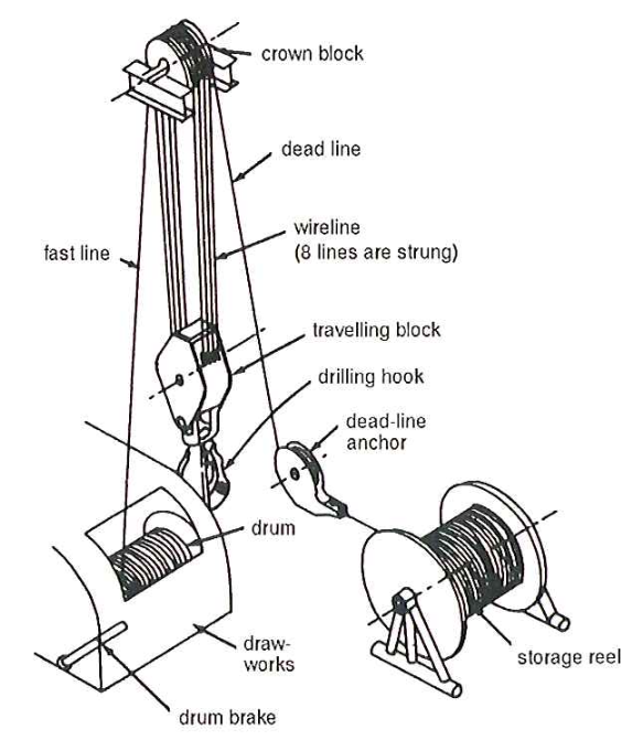
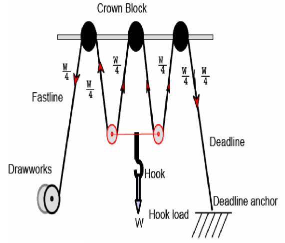
It is wound around the crown and traveling blocks several times, allowing heavy weights to be lowered or raised that one single line cannot carry.
- Load is equally distributed on each line; if you have 4-turns, each line will carry 1/8 of the hook load as shown in Fig. (24); if there are 6-turns (12-lines connecting crown and traveling block), so each line is carrying 1/12 of hook load.
- One end of this line is connected to the drum, which is called the fast line, and the other end is connected to the deadline anchor, which is called the deadline.
- Reel speed of fast line =NU. Of lines × speed of traveling block.
- Reel speed is a function of the number of pulleys and derrick height.
- The drum surface isn’t smooth; it has to groove on its surface to provide more security to the first layer of the drilling line instead of being flat. Also, it has two Roller Guides at its ends to prevent fast lines from contacting and wearing of the drum cover.
Automatic Pipe Handling
In offshore operations where the high winds and/or offshore rig motion may affect the cranes, handling drill pipe and casing pipe in rough weather is an unsafe operation not devoid of danger. In particular, on drill ships, where we store the pipe below decks, we must abandon its transfer to the rig floor for safety reasons long before stopping drilling operations on the rig floor. Without an additional drill pipe to add to the drill string, the operations cannot proceed. In addition, the rig must stop the operations and wait for the weather and/or sea conditions to improve.
Waiting, mainly offshore, is expensive, and hydraulic pipe handling systems were developed to overcome this problem. Initially, the pipe handling systems were manually operated and only designed to deliver pipe from below the deck to the drill floor. It did, however, not take long for the industry to develop automatic pipe handling systems and systems capable of making up stands and racking them in the derrick.
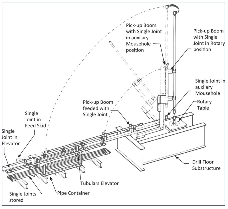
Pipe handling systems have the advantage of being capable of operating in rough weather and thus reducing downtime. They remove the pipe handling operation, the operation responsible for most accidents on the rig, from the drilling crew, thereby considerably increasing safety on the rig floor. The disadvantages are that they are expensive, relatively complicated, and slow operation. Figure 25 shows a pick-up/lay-down system.
Stand-handling systems are also used on jackup rigs and land rigs. In the latter case, they also confer
the benefit of a reduced noise level in populated areas.